abh_a571_full_specs
Open the original PDF document
View PDFAluminum Continuous Geared Hinges

Full Surface
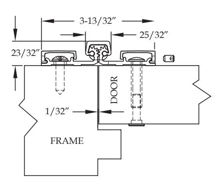
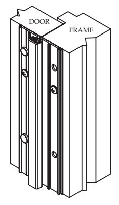
A571 HD
Standard Features
- Full surface, heavy duty
- No Door Inset, Flush Mount
- Bi-fold applications
- 48" door width maximum
- 450 lbs. door weight maximum
- • Fasteners : 12-24 x ⅞" undercut self-drilling, thread-forming tek machine screws for frame and ¼-20 sex bolts and shoulder bolts for door
- • Standard lengths : 79", 83", 85", 95" and 120"
- • Finishes : Clear, dark bronze and black anodized
-
• Fire Rating
- Approved for use on metal swinging type minutes (Specify " FR " option for 3 hour rating)
- Approved for use on wood swinging 60 minutes (Specify " FR " option for 90 minute rating)
Options Available
• See pages F-7 to F-8 for option availability and details

Aluminum Continuous Geared Hinges

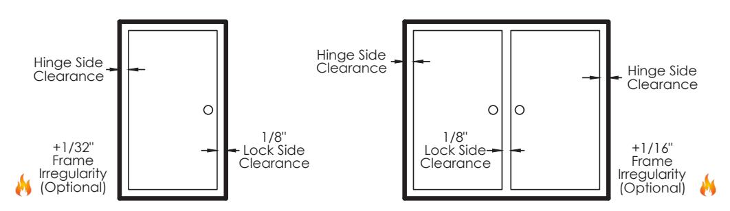
Door Clearance Chart Squared Edge
| Single Door - Squared Edged | ||||||||
|---|---|---|---|---|---|---|---|---|
| Hing | ge Model |
Hinge
Thickness |
+ |
Lock Side
Clearance |
+ |
*Frame //
Irregularity (OPTIONAL) |
= |
Square Edged Door
Undersized (Single) |
|
Full
Concealed |
A110, A110WT, A111
A111WT, A120,A140, A150, A160, A240, A260, A270, A410 |
5/16" | + | 1/8" | + | 1/32" | = | 15/32" |
| A130, A135 | 13/16" | + | 1/8" | + | 1/32" | = | 31/32" | |
|
Half
Surface |
A211, A213, A450, A460,
A520, A530, A540, A550 |
3/16" | + | 1/8" | + | 1/32" | = | 11/32" |
|
Full
Surface |
A210, A570, A571, A575 | 1/16" | + | 1/8" | + | 1/32" | = | 7/32" |
Single Door
Pair of Doors
| Pair of Doors - Squared Edged | ||||||||
|---|---|---|---|---|---|---|---|---|
| Hinge Model |
Hinge
Thickness (Pair) |
+ |
Lock Side
Clearance |
+ |
*Frame //
Irregularity (OPTIONAL) |
= |
Square Edged Door
Undersized (Pair) |
|
|
Full
Concealed |
A110, A110WT, A111
A111WT, A120, A140, A150, A160, A240, A260, A270, A410 |
5/8" | + | 1/8" | + | 1/16" | = | 13/16" |
| A130, A135 | 1-5/8" | + | 1/8" | + | 1/16" | = | 1-13/16" | |
|
Half
Surface |
A211, A213, A450, A460,
A520, A530, A540, A550 |
1/4" | + | 1/8" | + | 1/16" | = | 7/16" |
|
Full
Surface |
A210, A570, A571, A575 | 1/8" | + | 1/8" | + | 1/16" | = | 5/16" |
* 1/16& quot; Frame Irregularity Allowance, Optional and included in all Total Door Undersize for single and pairs of doors

Aluminum Continuous Geared Hinges

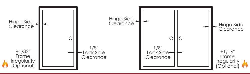
Door Clearance Chart Beveled Edge
| Single Door - Beveled Edged | ||||||||||
|---|---|---|---|---|---|---|---|---|---|---|
| Hinç | ge Model |
Hinge
Thickness |
+ |
Lock Side
Clearance |
+ |
* Frame ()
Irregularity (OPTIONAL) |
+ |
Beveled
Door Clearance |
= |
Beveled
Edged Door Undersized (Single) |
|
Full
Concealed |
A110, A110WT, A111
A111WT, A120,A140, A150, A160, A240, A260, A270, A410 |
5/16" | + | 1/8" | + | 1/32" | + | 1/32" | = | 1/2" |
| A130, A135 | 13/16" | + | 1/8" | + | 1/32" | + | 1/32" | = | 1" | |
|
Half
Surface |
A211, A213, A450, A460,
A520, A530, A540, A550 |
3/16" | + | 1/8" | + | 1/32" | + | 1/32" | = | 3/8" |
|
Full
Surface |
A210, A570, A571, A575 | 1/16" | + | 1/8" | + | 1/32" | + | N/A | = | 7/32" |
Single Door
Pair of Doors
| Pair of Doors - Beveled Edged | ||||||||||
|---|---|---|---|---|---|---|---|---|---|---|
| Hinç | ge Model |
Hinge
Thickness (Pair) |
+ |
Lock Side
Clearance |
+ | * Frame () Irregularity (OPTIONAL) | + |
Beveled
Door Clearance |
= |
Beveled
Edged Door Undersized (Pair) |
|
Full
Concealed |
A110, A110WT, A111
A111WT, A120, A140, A150, A160, A240, A260, A270, A410 |
5/8" | + | 1/8" | + | 1/16" | + | 1/16" | = | 7 8 " |
| A130, A135 | 1-5/8" | + | 1/8" | + | 1/16" | + | 1/16" | = | 1-%" | |
|
Half
Surface |
A211, A213, A450, A460,
A520, A530, A540, A550 |
1/4" | + | 1/8" | + | 1/16" | + | N/A | = | 7/16" |
|
Full
Surface |
A210, A570, A571, A575 | 1/8" | + | 1/8" | + | 1/16" | + | N/A | = | 5/16" |
* 1/16& quot; Frame Irregularity Allowance, Optional and included in all Total Door Undersize for single and pairs of doors

A571 - ALUMINUM GEARED HINGE, FULL FRAME, NO INSET, FULL SURFACE 79" 83" 85" 95" 120" FRAME DOOR 7-1/2 7-1/2 7-1/2 7-1/2 7-1/2 Ø 7/32 Ø 7/32 LOCATOR HOLE TYP. LOCATOR HOLE TYP. 17-1/2 17-1/2 17-1/2 17-1/2 17-1/2 22-1/2 22-1/2 22-1/2 22-1/2 22-1/2 Ø 3/8 27-1/2 27-1/2 27-1/2 27-1/2 27-1/2 37-1/2 -37-1/2 37-1/2 37-1/2 -37-1/2 FRAME 45-1/2 45-1/2 47-1/2 47-1/2 47-1/2 CLOSED POSITION 55-1/2 -55-1/2 -3/4 57-1/2 -57-1/2 57-1/2 -60-1/2 60-1/2 62-1/2 65-1/2-65-1/267-1/2 67-1/2 -90° OPENING 180° OPENING 72-1/2 72-1/2 72-1/2 75-1/2 77-1/2 77-1/2 NOTES: 1. HINGES CUT TO CUSTOM LENGTH ARE CUT 82-1/2 FROM THE BOTTOM. 85 2. ALL DIMENSIONS ARE IN INCHES. 3. ALL DIMENSIONS ARE TO CENTERLINE OF HOLES. 87-1/2 XX" DENOTES LOCATOR HOLE. 92-1/2 97-1/2 102-1/2
| STANDARD HINGE SIZES & SO | REW | DET | AIL | |||
|---|---|---|---|---|---|---|
| NOMINA | AL DOOR HEIGHT | 6'8" | 7'0" | 7'2" | 8'0" | 10'0" |
| ACTUA | L HINGE LENGTH | 79" | 83" | 85" | 95" | 120" |
| FRAME |
12-24 x 1" PHILLIPS PAN HEAD, SELF DRILLING,
THREAD FORMING TEK MACHINE SCREW |
13 | 14 | 13 | 15 | 18 |
| DOOR |
1/4-20 x 1-1/4" x 3/8 DIA. SEX BOLT &
1/4-20 x 1-1/4" PH. HEAD SHOULDER SCREW |
9 | 10 | 9 | 11 | 14 |
| DOOR | 12-24 x 1" PH. PN. HD. SELF DRILLING TEK SCREW | 3 | 4 | 3 | 4 | 4 |
A571-ALUMINUM GEARED HINGE-03.DWG
112-1/2
A571 ALUMINUM GEARED HINGE
PAGE 1 OF 1 REVISED 08-19-22
www.abhmfg.com E-mail: abhinfo@abhmfg.com Architectural Builders Hardware Mfg., Inc. 1222 Ardmore Ave., Itasca, IL 60143 630.875.9900; FAX 800.9FAXABH (932.9224)

www.abhmfg.com E-mail: abhinfo@abhmfg.com Architectural Builders Hardware Mfg., Inc. 1222 Ardmore Ave., Itasca, IL 60143 630.875.9900; FAX 800.9FAXABH (932.9224)
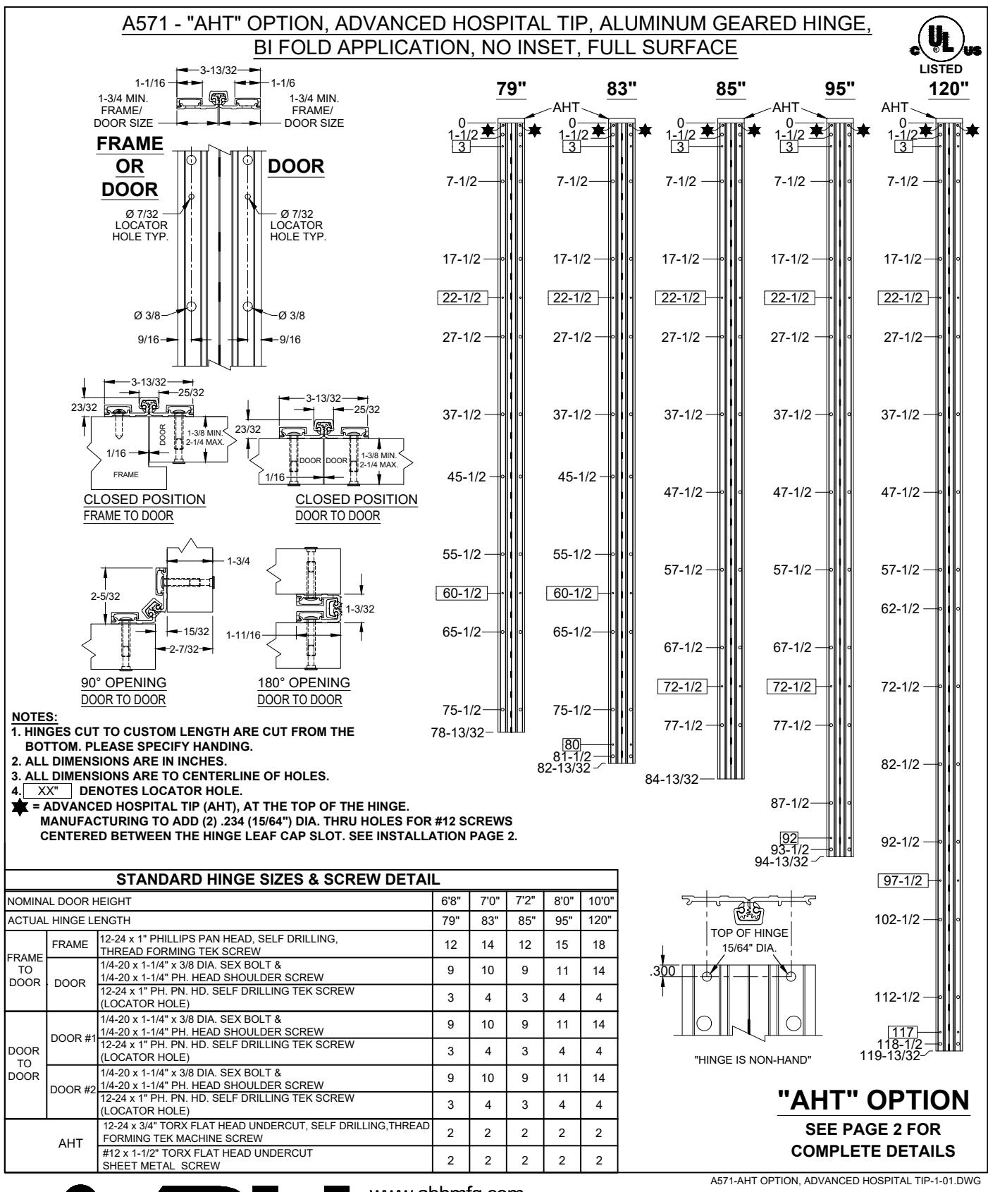
A571 - "AHT" OPTION
A5/1 - "AHT" OPTION ADVANCED HOSPITAL TIP
© 2020 ABH Mfg., Inc. printed in USA
PAGE 1 OF 2 REVISED 8-12-21
A571 - "AHT" OPTION, ADVANCED HOSPITAL TIP, ALUMINUM GEARED HINGE, BI FOLD APPLICATION, NO INSET, FULL SURFACE
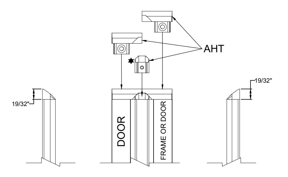
A571 AHT (ADVANCED HOSPITAL TIP) INSTALLATION INSTRUCTIONS
- 1. INSTALL TOP OF HINGE 19/32" FROM THE TOP OF THE DOOR
- 2. BEFORE INSTALLING DOOR AND FRAME LEAF COVERS, FASTEN DOOR AND FRAME SIDE HOSPITAL TIP SECTIONS
3. INSTALL DOOR SIDE AHT SECTION
- a. SLIDE AHT SECTION INTO SLOT ON HINGE LEAF, THIS WILL LINE UP WITH THE PREDRILLED HINGE LEAF THRU-HOLE
- b. FOR METAL DOORS, MARK HOLE LOCATION, THEN DRILL AND FASTEN THE AHT SECTION USING PROVIDED 12-24 X 7/8" TORX FLAT HEAD, UNDERCUT, SELF-DRILLING, THREAD FORMING TEK MACHINE SCREW
- c. FOR WOOD DOORS, MARK HOLE LOCATION AND DRILL 3/16" PILOT HOLE, FASTEN AHT SECTION USING PROVIDED #12 X 1-1/2" TORX FLAT HEAD , UNDERCUT WOOD SCREW
4. INSTALL FRAME SIDE AHT SECTION
- a. SLIDE AHT SECTION INTO SLOT ON HINGE LEAF, THIS WILL LINE UP WITH THE PREDRILLED HINGE LEAF THRU-HOLE
- b. FOR METAL FRAMES, MARK HOLE LOCATION, THEN DRILL AND FASTEN THE AHT SECTION USING PROVIDED 12-24 X 7/8" TORX FLAT HEAD, UNDERCUT, SELF-DRILLING, THREAD FORMING TEK MACHINE SCREW
- c. FOR WOOD FRAMES, MARK HOLE LOCATION AND DRILL 3/16" PILOT HOLE, FASTEN AHT SECTION USING PROVIDED #12 X 1-1/2" TORX FLAT HEAD, UNDERCUT WOOD SCREW
- 5. BEFORE TIGHTENING THE SCREWS DOWN COMPLETELY, DOOR AND FRAME AHT SECTIONS SHOULD BE FLUSH WITH THE TOP OF THE DOOR.
- 6. INSTALL DOOR AND FRAME LEAF COVERS

www.abhmfg.com E-mail: abhinfo@abhmfg.com Architectural Builders Hardware Mfg., Inc. 1222 Ardmore Ave., Itasca, IL 60143 630.875.9900; FAX 800.9FAXABH (932.9224)
A571-AHT OPTION, ADVANCED HOSPITAL TIP-2-01.DWG
REVISED 8-12-21 PAGE 2 OF 2 A571 - "AHT" OPTION ADVANCED HOSPITAL TIP c 2020 ABH Mfg., Inc. printed in USA

® www.abhmfg.com
E-mail: abhinfo@abhmfg.com Architectural Builders Hardware Mfg., Inc. 1222 Ardmore Ave., Itasca, IL 60143 630.875.9900; FAX 800.9FAXABH (932.9224)
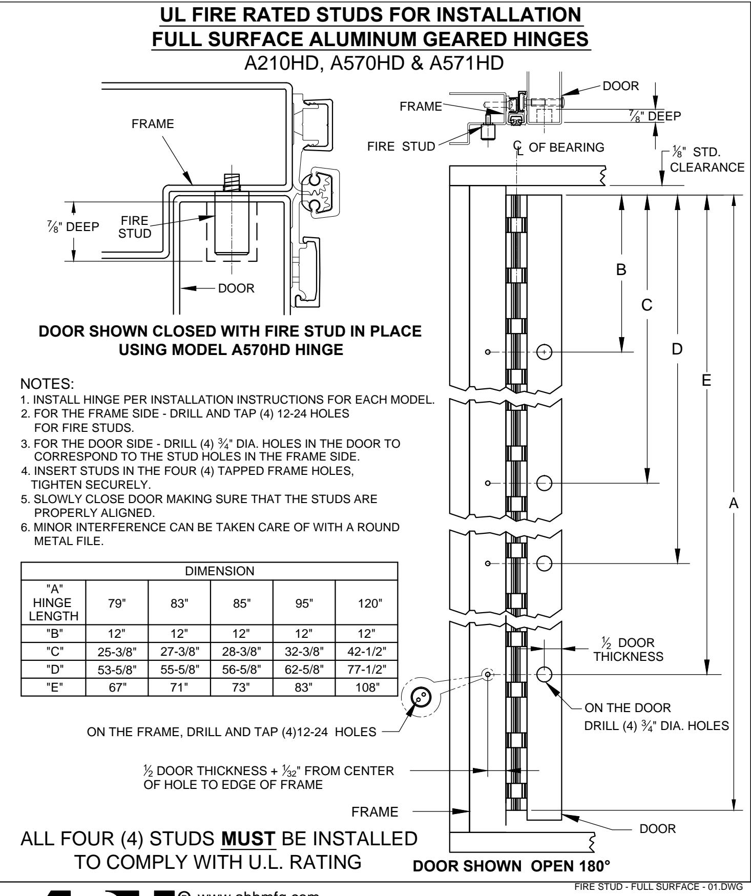
FIRE STUD -FULL SURFACE
PAGE 1 OF 1 REVISED 10-05-16
© 2016 ABH Mfg., Inc. printed in USA
INSTALLATION INSTRUCTIONS FOR FULL SURFACE HINGES
A210HD, A570HD & A571HD
- A. All uncut standard length hinges are non-handed and can be used for right or left hand doors.
- B. Standard length hinges are supplied slightly shorter than nominal door height to accommodate threshold and carpeting clearances.
CUTTING THE HINGE TO FIT
- Keep hinge in the closed position. If necessary remove door/frame leaf caps.
- Cut one end of the hinge only. The hinge must be installed with the cut end at the bottom to keep the templated hole pattern at the top.
- Use a Metal Cutting Saw cut through the gear cap first.
Note: If cut length interferes with a set screw bearing remove it and switch it with a plain bearing above the cut location.
ATTACHING THE HINGE TO THE FRAME
- 1. Shim the hinge to be 1/8" below the header.
- 2. Hold hinge in the open position and align frame leaf withe the inner edge of the door frame.
- 3. Mark or Center Punch hole locations: two holes at the top and two at the bottom.
- 4. Using the provided Self Drilling/Thread Forming Screws please proceed to fasten the frame leaf in marked holes.
Note: If using wood screws drill a 5/32" pilot hole.
PREPARE THE DOOR
- 5. Position Door in the opening and shim for proper clearances.
- 6. Align the top end of the hinge to be absolutely flush with the top of the door.
- 7. Mark the four LOCATOR HOLE locations (shown on template) using the provided small center punch.
- 8. Using a #3 philips head bit, attach the door leaf to the door through the LOCATOR HOLES with the provided pan head screws
- 9. Remove any shims and check for proper clearances and door operation.
- 10. If door sags slightly, note amount of adjustment needed to bring door back into alignment.
DO NOT PROCEED UNTIL DOOR OPERATES PROPERLY
- 11. Locate and mark for the thru-bolts in the door using the large punch provided.
- 12. Remove door and use a 3/8" drill bit to drill holes at marked locations
ATTACHING DOOR TO THE HINGE
13. Fasten the door to door leaf using the provided sex bolts and shoulder screws
Note: Always install the shoulder screws on the secured side of the door
14. Mark or Center Punch the remaining frame leaf hole locations. Using the provided flathead or pan head self drilling/thread forming screws completely fasten the frame leaf.
INSTALL THE LEAF COVERS
Note: Before installing the door leaf cover make sure the the set screws do not protruded into the interior of the cover.
- 15. Line up the end of the door leaf cover with the top end of the hinge
- 16. Starting at the top, apply pressure along the length of the cover and snap into place as you go down the length of the hinge.
- 17. When the cover is on tighten the set screw to secure it.
- 18. Install the frame leaf cover by first hooking it onto the outside edge of the frame leaf.
- 19. Starting at the top, apply pressure along the length of the cover and snap into place as you go down the length of the hinge.
Note: If using a hammer, use a block of wood to protect the cover.
REINFORCING AND RIVNUTS
- No reinforcing is necessary except on extremely high-frequency, extremely heavy or extra-wide doors.
- Rivnuts are recommended for use in the frame when the door exceeds 450lbs.
Note:RIVNUTS are not to be used with Fire Rated Hinges
GROUT/SLUSHED-IN FRAMES
It is recommended that a mudguard be installed behind the frame for ease of installation. Do not use self-drill screws with grouted steel frames without a mudguard. If no mudguard has been used, drill holes through frame and remove grout for screw clearances. Do not oversize hole.
| SCREW DETAIL | |||||||
|---|---|---|---|---|---|---|---|
| FRAME | IDRILLING, I TREAD FORMING I EN MACHINE SCREW | ||||||
| FRAME |
12-24 x 1" PHILLIPS PAN HEAD, SELF DRILLING,
THREAD FORMING TEK MACHINE SCREW |
||||||
| DOOR |
1/4-20 x 1-1/4" x 3/8 DIA. SEX BOLT &
1/4-20 x 1-1/4" PH. HEAD SHOULDER SCREW 12-24 x 1" PH. PN. HD. SELF DRILLING TEK SCREW (LOCATOR HOLE) |
||||||
The following actions will void any warranty, expressed or implied.
- · Failure to Install the hinge according to ABH's specifications and requirements
- Use of Fasteners other than those supplied with the hinge.
- Unauthorized field modifications including removing any of the bearings, altering the original finish or painting the hinge.