ZKTeco USA SC700 User Manual Guide
Open the original PDF document
View PDFUSER MANUAL (Professional)
Access Control Product RFID Series
Version: 1.1
Date: Feb., 2014
Introduction:
This document introduces user interface and menu operations. Besides, can be bundled Access 3.5 Security System is used with together. For installation, please refer to the Installation Guide.
Important Claim
Firstly thank you for purchasing this hybrid terminal product. Before use, please read this manual carefully to avoid the unnecessary damage! The company reminds you that the proper user will improve the use affect and authentication speed.
No written consent by our company, any unit or individual isn't allowed to excerpt, copy the content of this manual in part or in full, also spread in any form.
The product described in the manual maybe includes the software which copyrights are shared by the licensors including our company, Except for the permission of the relevant holder, any person can't copy, distribute, revise, modify, extract, decompile, disassemble, decrypt, reverse engineering, leasing, transfer, sub-license the software, other acts of copyright infringement, but the limitations applied to the law is excluded.
Reserve the final rights of modification and interpretation.
Due to the constant renewal of products, the company can not undertake the actual product in consistence with the information in the document, also any dispute caused by the difference between the actual technical parameters and the information in this document. Please forgive any change without notice.
-----
Table of Contents
| 1. Notice for Use | 1 |
|---|---|
| 1.1 About This Manual | 1 |
| 1.2 Use of the Touch Screen | |
| 1.3 Touch Operation | 2 |
| 1.4 Appearance of Device | 3 |
| 1.5 Main Interface | 3 |
| 2. Main Menu | 5 |
| 3. Add User | 6 |
| 3.1 Entering a User ID | 6 |
| 3.2 Entering a Name | 7 |
| 3.3 Enrolling an ID Card | |
| 3.4 Enrolling a Password | 3 |
| 3.5 User Role | |
| 3.6 User Verification | C |
| 3.6.1 Password Verification | C |
| 3.6.2 ID Card Verification | 10 |
| 4. User Management | 11 |
| 4.1 Edit a User | 11 |
| 4.2 Delete a User | 12 |
| 4.3 Query a User | 12 |
| 5. Communication Setting | 13 |
| 5.1 Communication Setting | 13 |
| 5.2 Wiegand Input | 14 |
| 5.3 Wiegand Output | 1 |
| 5.4 Customized Format | 15 |
| 6. System Setting | 17 |
| 6.1 General Parameter | 17 |
| 6.1.1 Keyboard Clicks | 17 |
| 6.1.2 Voice Prompts | 17 |
| 6.1.3 Volume | 18 |
| 6.1.4 Attendance | 18 |
| 6.2 Display Parameters | 19 |
| 6.2.1 Language | 19 |
| 6.2.2 Toolbar | 19 |
| 6.2.3 Sleep Time | 19 |
| 6.3 Shortcut Definition | 19 |
| 6.3.1 Shortcut Keys Using | 19 |
| 6.3.2 Shortcut Definition Setting | 20 |
| 6.4 Access Control Parameters | 21 |
|---|---|
| 6.4.1 Lock Delay | 21 |
| 6.4.2 Door Sensor Delay | 22 |
| 6.4.3 Door Sensor Mode | 22 |
| 6.4.4 Verification Type | 22 |
| 6.5 Update | 23 |
| 7. Data Management | 24 |
| 8. Date/Time Setting | 25 |
| 9. Auto Test | 26 |
| 9.1 Test Screen | 26 |
| 9.2 Test Voice | 26 |
| 9.3 Test Time | 27 |
| 9.4 Screen Calibration | 27 |
| 10. USB Disk Management | 29 |
| 11. System Information | 30 |
| 12. Appendix | 31 |
| 12.1 T9 Input Instruction | 31 |
| 12.2 USB | 31 |
| 12.3 Introduction of Wiegand | 32 |
| 12.3.1 Wiegand 26-bits Output Description | 33 |
| 12.3.2 Wiegand 34-bits Output Description | 34 |
| 12.3.3 Wiegand Customize Wiegand Format Description | 35 |
| 12.4 Anti-Pass Back | |
| 12.5 Environment-Friendly Use Description | 40 |
1. Notice for Use
Pls do not use the device in a direct sunshine environment, and avoid using in outdoor in summer. The working temperature ranges from degrees Centigrade. The heat dissipated during long-term operation may easily lead to response slowdown and verification pass rate decrease. It is recommended to use sunshades and heat sink devices for the device when using at outside.
1.1 About This Manual
- > The photograph in this manual may be different from that of the real product. The actual product to prevail.
- ➤ Characteristic Feature (The firmware application logic aspects):
(1) RFID Function
Supports IC Card or ID Card.
(2) User Access Options
Mainly have the following advanced access control functions:
- 1. User effective date
- 2. User effective time period
- 3. User multiple verification mode
- 4. Door valid time zone
- 5. Door open time function
- 6. Holidays time period
- 7. First-card normal open
- 8. Access control records of controller
- 9. Linkage function
- 10. Anti-passback of out or in
- 11. Master-Slave function of Wiegand
- 12. Anti-passback of time period
The above advanced Access Control functions should bundled Access3.5 Security System . For details, please refer to Access3.5 software user manual .
(3) U Disk Function
Support U disk uploading and downloading user data, does not support U disk upload to access control records.
(4) Support Network Communication
Through the Internet with Access Control 3.5 software communications.
(5) Attendance Function
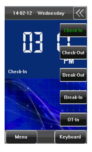
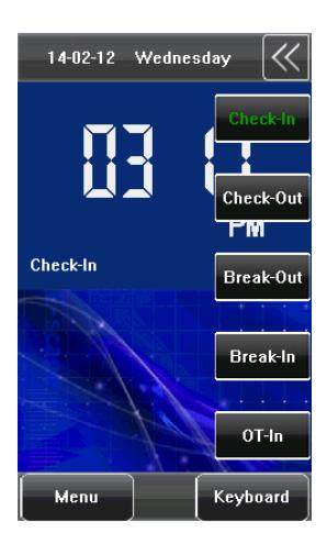
Press on the initial interface, the related status and function keys are displayed on the right corner of the interface for use. Including Check-In, Check-Out, Break-Out, Break-In, OT-In etc.
1.2 Use of the Touch Screen
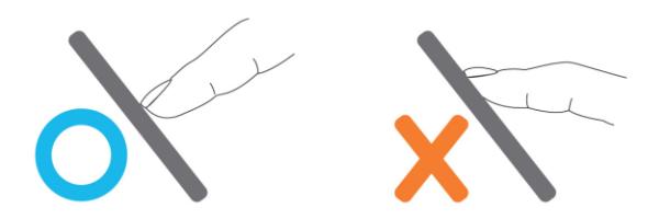
Touch the screen with one of your fingertips or the edge of a fingernail, as shown in the following figure. A broad point of contact may lead to inaccurate pointing.
When the touch screen is less sensitive to the touch, you can perform a screen calibration through the following menu operations. Press [Menu] > [Auto Test] > [Calibration] on the screen and a cross icon will be displayed. After you touch the center of the cross at five locations on the screen correctly, the system will automatically returns to the [Auto Test] menu. Press [Exit] to return to the [Menu] interface. For details, see the description in 9. Auto Test.
Smear or dust on the touch screen may affect the performance of the touch screen. Therefore, try to keep the screen clean and dust-free.
1.3 Touch Operation
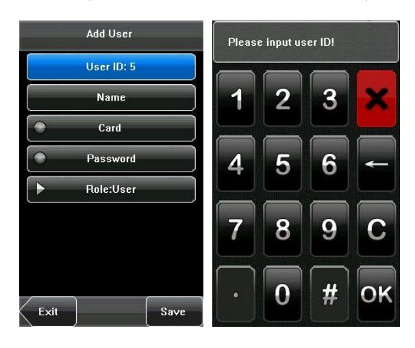
1. Enter numbers: Press the [User ID] key. The system will automatically display the number input interface. After entering the user ID, press [OK] to save or press [X] to cancel and return to the previous interface.
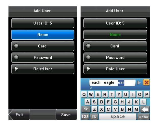
2. Enter Text: Press the [Name] key. The system will automatically display the text input interface. After entering the
user name, press [X] to close the text interfaces, and then press [save] and return to the previous interface.
1.4 Appearance of Device
1.5 Main Interface
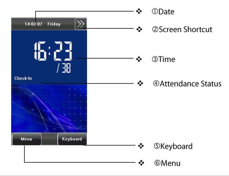
- ODate : The current date is displayed.
- ②Screen Shortcut : Press these shortcut keys to display the attendance status.
- 3 Time : The current time is displayed. Both 12-hour and 24-hour time systems are supported.
- Attendance Status : The current attendance status is displayed.
- ⑤ Keyboard : By pressing this key, you can enter the digital input interface.
- 6 Menu: You can enter the main menu by pressing this key.
2. Main Menu
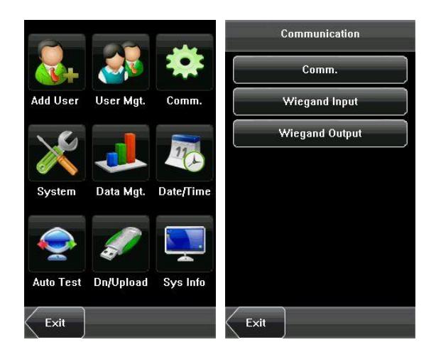
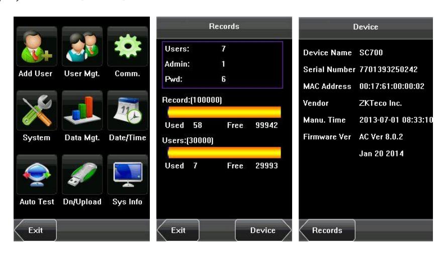
Press [Menu] on the initial interface to access the main menu, as shown in the following figure:
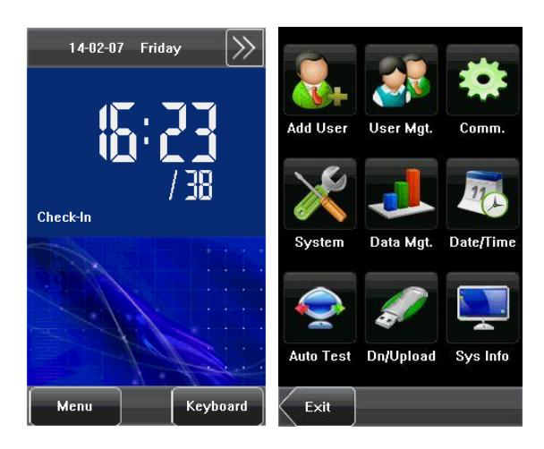
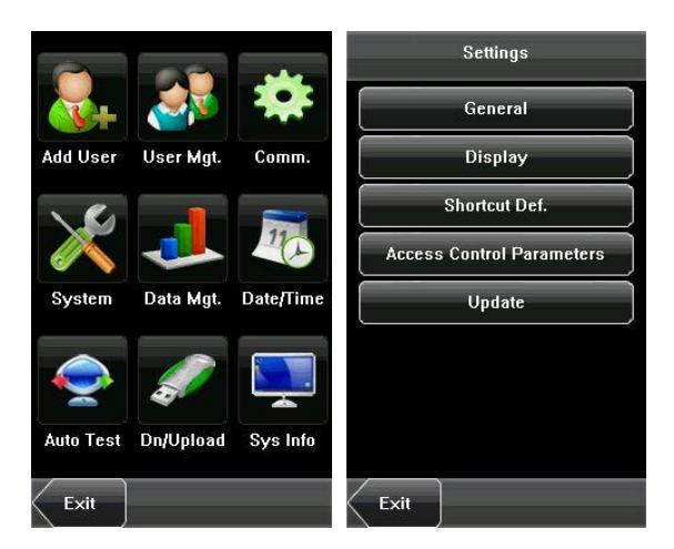
The main menu includes nine sub menus:
Add User: Through this submenu, you can add a new user and input the information on the device, including the user ID, name, card, password, Role (permissions).
User Mgt. : Through this submenu, you can browse the user information stored on the device, including the user ID, name, card, password, Role. Here you can also Add, Modify .Query, or Delete a user's information.
Comm.: Through this submenu, you can set related parameters for communication between the device and PC, including the IP Address, Subnet mask, Gateway, Device ID and Comm. Key.
System: Through this submenu, you can set system-related parameters, including the General, Display, Shortcut Def., Access Control Parameters, and Update.
Data Mgt.: Through this submenu, you can perform management of data stored on the device, for example, deleting all data, clear administrator, restore to factory settings.
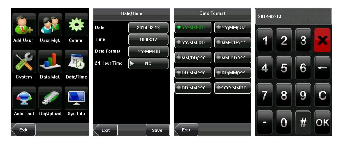
Date/Time: Through this submenu, you can set Date, Time, Date Format, and 24-Hour Time.
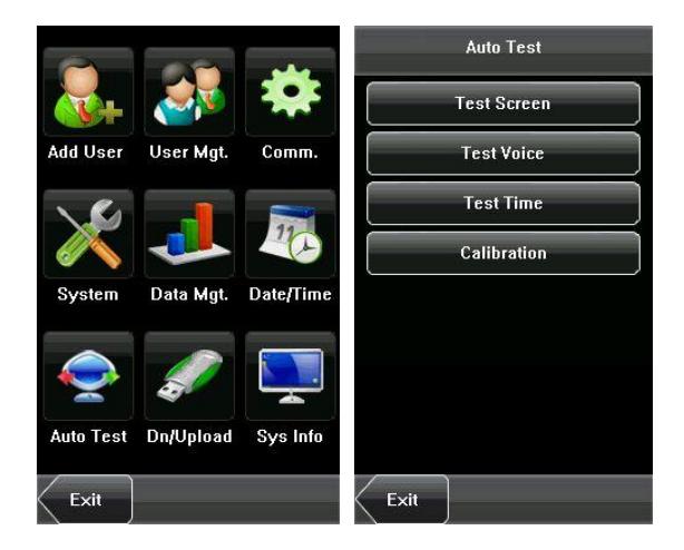
Auto Test: This submenu enables the system to automatically test whether functions of various modules are normal, including the screen, voice, Time and screen calibration.
Dn/Upload: Through this submenu, you can download user information and attendance data stored in the device through a USB disk and upload user information to the device.
Sys Info.: Through this submenu, you can browse the capacity records of Access Control (100,000), Users (30,000) and device information.
Any user can access the main menu by pressing the [ Menu ] key if the system does not have an administrator. If had a administrator, the device needs to verify the administrators' identity before granting them access to the main menu. To ensure device security, it is recommended to set an administrator when using the terminal initially.
-----
3. Add User
Press [Add User] on the main menu interface to display the [Add User] interface as shown below:
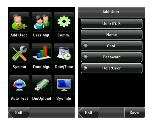
Steps of adding a user: Input user ID > Input name > Register an ID card > Enroll password > Set Role
User ID: Enter a user ID. 1 to 9 digits user IDs are supported by default.
Name. Enter a user name. 24 characters user names are supported by default.
Card: Press an ID card can register a new user.
Password : Enroll a user's password. The device supports 1-8 digit passwords by default.
Role : Set the rights of a user. A user is set to ordinary user by default and can also be set to administrator .
Tip: When a new user registers on the device, it sets the defaulted access control function at the same time. Other complex advanced access control function need bundled Access 3.5 software for settings.
3.1 Entering a User ID
The device automatically allocates an ID starting from 1 for every user in sequence. If you use the ID allocated by the device, you may skip this section.
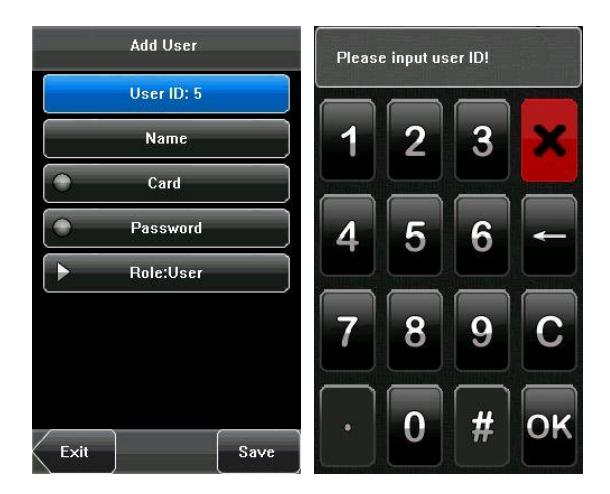
1. Press [ User ID ] on the [ Add User ] interface to display the user ID management interface.
Tip: The user ID can be modified during initial enrollment, but once enrolled, it cannot be modified.
2. On the displayed keyboard interface, enter a user ID and press [ OK ]. If the message "User ID exist!" is displayed, enter another ID.
Tip: The device supports 1 to 9 digits user IDs by default. If you need to extend the length of current user ID numbers, please consult our commercial representatives or technical pre-sales.
3. After the user ID is entered, press [ Save ] to save the current information and return to the previous interface. Press [ Exit ] to return to the previous interface without saving the current information.
3.2 Entering a Name
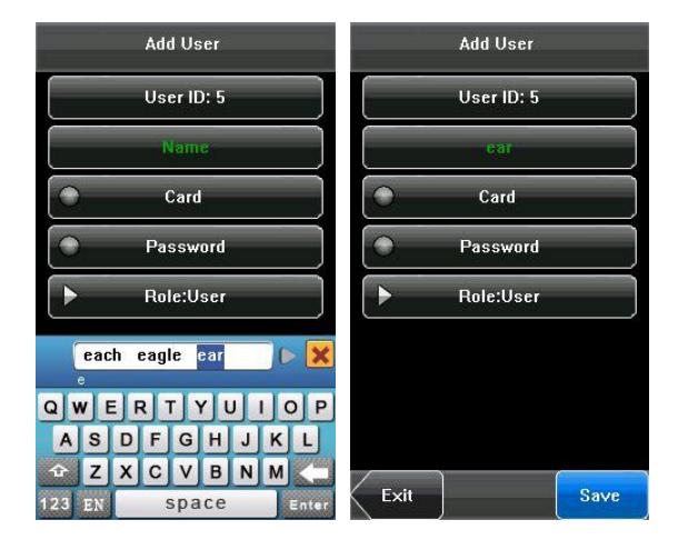
Use T9 input method to enter the user name through the keyboard.
- 1. Press [Name] on the [Add User] interface to display the name input interface.
- 2. On the displayed keyboard interface, enter a user name and press [ Enter ], and then press [ X ].
For details of operations on the keyboard interface, see 12.1 T9 Input Instruction.
3. After the user name is entered, press [ Save ] to save the current information and return to the previous interface. Press [ Exit ] to return to the previous interface without saving the current information.

3.3 Enrolling an ID Card
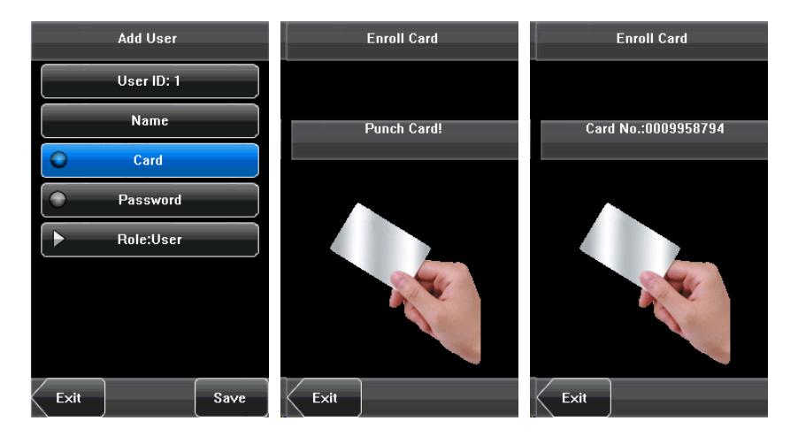
1. Press [Card] on the [Add User] interface to display the [Enroll Card] interface.
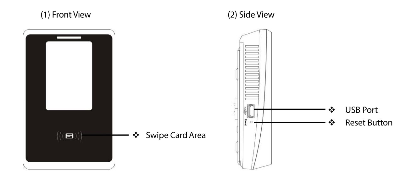
- 2. The [Punch Card!] interface pops up as shown below. Swipe your ID card properly in the swiping area. For details, see 1.4 Appearance of Device.
- 3. Press [Save] to save the current information and return to the previous interface. Press [Exit] to return to the previous interface without saving the current information.
Tip: Default is 125 KHz Proximity Card, Optional 13.56 MHz Mifare Card.
3.4 Enrolling a Password
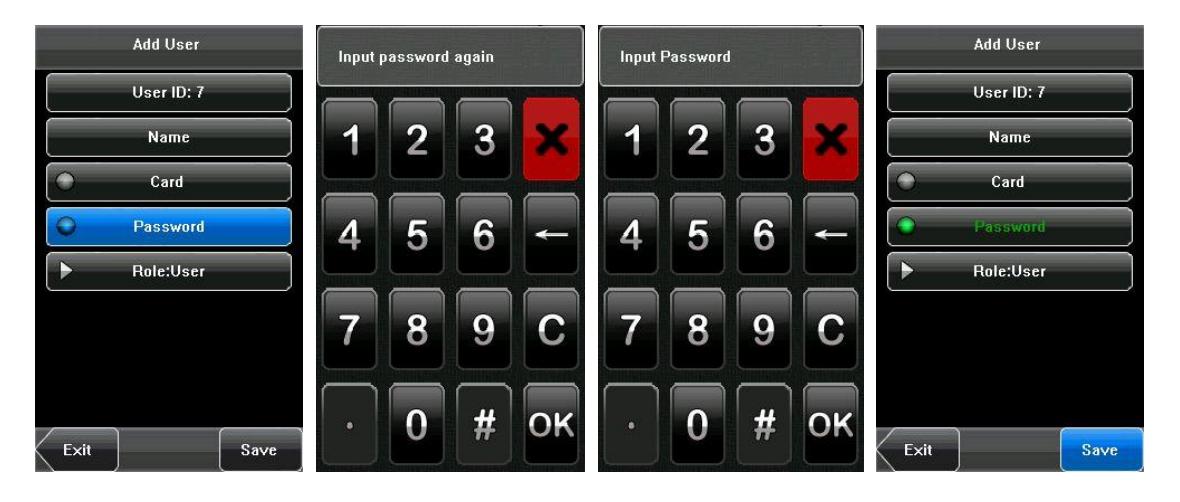
- 1. Press [ Password ] on the [ Add User ] interface to display the password management interface.
- 2. On the displayed keyboard interface, enter a password and press [OK]. Re-enter the password according to the system prompt and then press [OK].
- 3. After the password is entered, an interface is displayed as shown below. Press [Save] to save the current information and return to the previous interface. Press [Exit] to return to the previous interface without saving the current information.
3.5 User Role
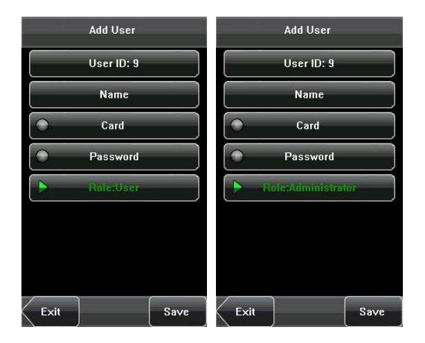
There are two types of permissions of users: the user and administrator . Ordinary users are only granted the rights of password or card verification. Administrators are granted access to the main menu for various operations apart from having all the privileges granted to ordinary users.

Indicate the user is administrator.
- 1. On the [Add User] interface, press [Role: User] to change the user to an administrator.
- 2. After the modification is done, the interface is as shown below. Press [ Save ] to save the current information and return to the previous interface; press [ Exit ] to return to the previous interface without saving the current information.
3.6 User Verification
After enrolling, you can verify validity that ID card or password on the initial interface. User verification must be consistent with verification type. The setting method of verification type, please refer to <u>6.4.4 Verification Type</u>.
3.6.1 Password Verification
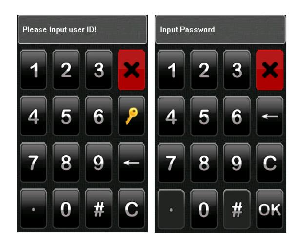
- 1. Press [Keyboard] on the screen.
- 2. Enter the user ID and then press to enter the password verification mode. If the prompt "Not registered!" is displayed, the riser ID does not exist.
- 3. Enter the password and press [OK] to start the password comparison.
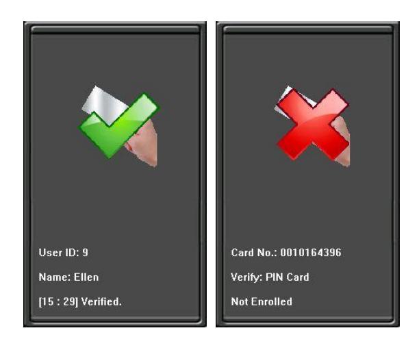
- 4. If the verification is successful, the device will prompt "Verified", otherwise the device will prompt "Verify fail" and return to initial interface.
- 1)
- 2)
- 3)
4. User Management
User Management: Manage the registered users. Browse the user information, including the user ID, Name, card, Password, Role (Permission). Through this interface to add, query, edit or delete the basic information of users.
Press [User Management] on the main menu interface to display the user management interface.
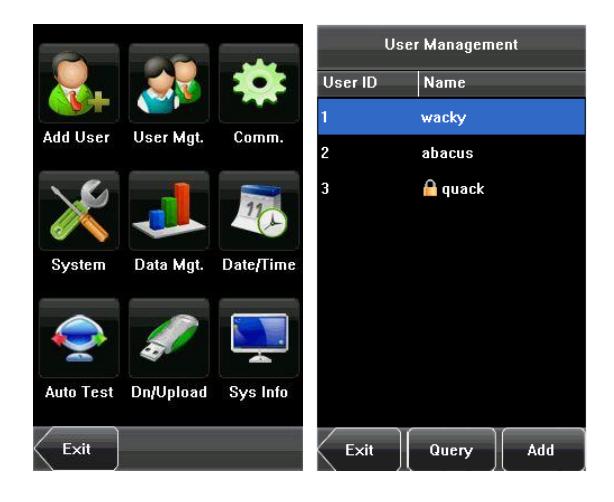

This user is an administrator.
4.1 Edit a User
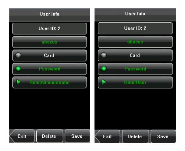
Press a user name from the list to enter the [ User Info ] interface.
The User ID cannot be modified, and the other operations are similar to those performed in add a user. You can modify user name, password, and the role, re-enroll ID card.
For example: Change the user rights from administrator to ordinary user. As shown below.
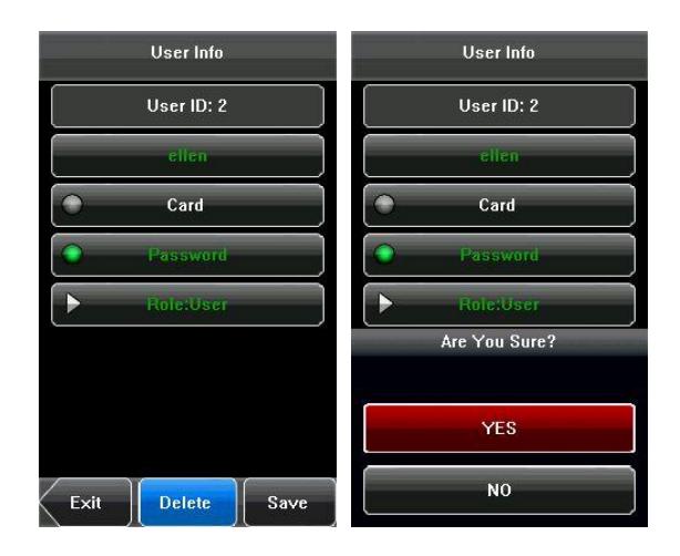
4.2 Delete a User
On the [User Info] interface, you can delete all or partial user information.
- 1. Press [Delete] to delete a user.
- 2. On the displayed interface, press [YES] to delete the current user or [NO] to return to the previous interface.
- 3. On the [ User Info ] interface, press [ Name ] or [ Password ] to delete the related user information and to re-enroll the new information follow the device prompt.
4.3 Query a User
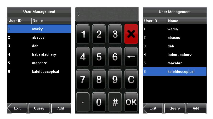
To facilitate administrators to locate a user quickly from a large number of enrolled users, the device enables to query by "User ID".
User ID Query:
- 1. Press [Query] on the [User Management] interface to display the User ID query interface.
- 2. Enter the user ID on the displayed interface, and press [OK] to locate the cursor on the desired user.
5. Communication Setting
You can set related parameters for the communication between the device and PC, including the IP address , Subnet Mask, Gateway, Device ID, Comm. Key, Wiegand Input and wiegand Output .
5.1 Communication Setting
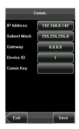
IP Address: The IP address is 192.168.1.201 by default and can be changed as required.
Subnet Mask : The subnet mask is 255.255.255.0 by default and can be changed as required.
Gateway : The gateway is 0.0.0.0 by default and can be changed as required.
Device ID: This parameter is used to set the ID of device from 1 to 254.
Comm. Key : To enhance the security of attendance data, you can set a password for the connection between the device and PC. Once the password is set, you can connect the PC with the device to access the attendance data only after entering the correct password. The default password is 0 (that is, no password), 1 to 6 digits passwords are supported.
5.2 Wiegand Input
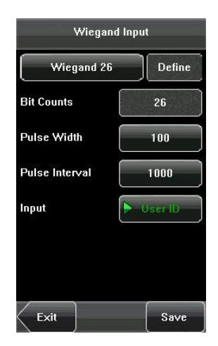
Bit counts: Wiegand data digit length.
Pulse width: Pulse width is 100 microseconds by default, which can be adjusted from 1 to 1000.
Pulse interval: It is 1000 microseconds by default, which can be adjusted between 1 and 10000.
Input: Content contains in Wiegand input signal, including User ID or Card No.
Tip: Support connect to third party access control panel by using Wiegand interface.
For details about the Wiegand, see 12.3 Introduction of Wiegand.
5.3 Wiegand Output
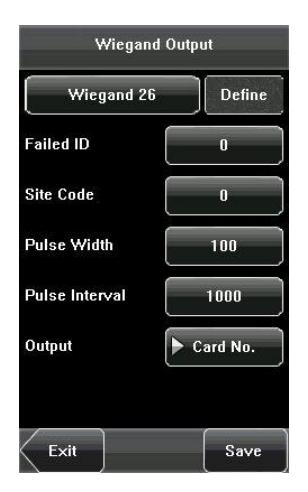
Wiegand Format: The system has two built-in formats Wiegand 26-bits and Wiegand 34-bits , and also supports the format customization function to meet individualized requirements.
Failed ID : Refers to the value output by the system upon verification failure. The output format is subject to the setting of Wiegand format. The default value scope of Failed ID is 0-65535.
Site Code : The site code is used for a customized Wiegand format. The Site Code is similar to the device ID, but the Site Code is customizable and can be duplicated among different devices. The default value scope of the Site Code is .
Pulse Width : Refers to the width of the Wiegand pulse in microseconds. The default value scope of the pulse width is .
Pulse Interval : Refers to the interval of the Wiegand pulse in microseconds. The default value scope of the pulse width is .
Output : Refers to the contents output upon successful verification. You can select User ID or Card Number as the output.
For details about the Wiegand, see 12.3 Introduction of Wiegand.
5.4 Customized Format
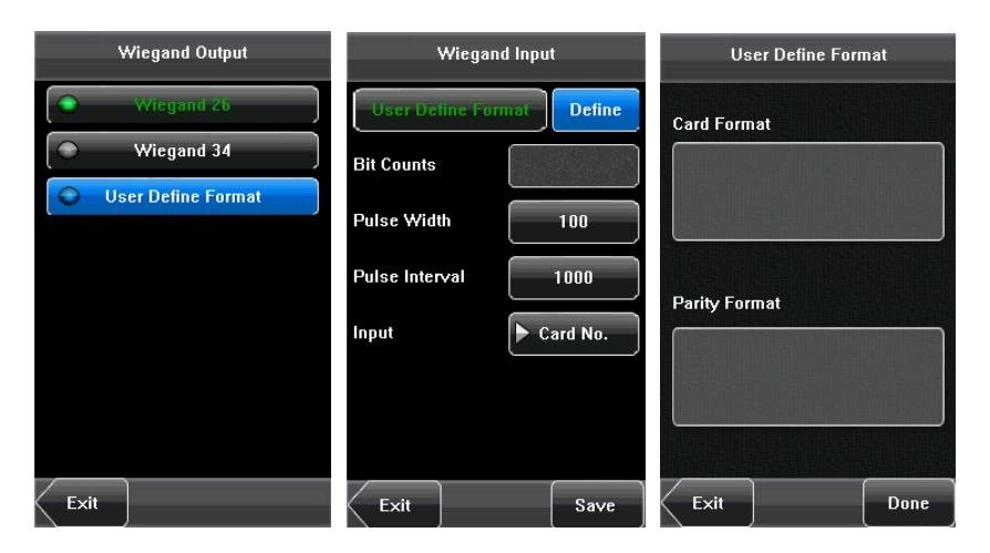
Apart from the two built-in formats Wiegand 26-bits and Wiegand 34-bits , the system also supports the format customization function to meet individualized requirements.
The customized format consists of two character strings: the Card Format bits and Parity Format bits. These two character strings need to be defined separately.
Card Format bits define the number of binary bits output by Wiegand as well as the meaning of each bit. The data bits output by Wiegand can be a card number (C), site code (s), facility code (f), manufacturer code (m) and parity bits (p).
Parity Format bits define the check mode of each bit in Card Format and ensure the correctness of Card Format during transfer through the parity check. The parity bits can be set to odd check (o), even check (e) and both odd check and even check (b).
There is a one-to-one correspondence relationship between the data bits and parity bits.
For example, the Wiegand 26 can be customized as follows:
Definition of Card Format bits: psssssssscccccccccccc
Definition of Parity Format bits: eeeeeeeeeeeeooooooooooo
Tip: Wiegand26 consists of 26 bits. The first bit is the even parity bit of bits 2 to 13; the 26th bit is the odd parity bit of bits 14 to 25; the 2th to the 9th bits are the site code; the 10th to the 25th bits are the card number. For details about the Wiegand, see 12.3 Introduction of Wiegand.
6. System Setting
Through the [System] menu, you can set system-related parameters, including the General, Display, Shortcut Def., Access Control Parameters and Firmware Update.
6.1 General Parameter
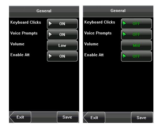
The general parameter settings include Keyboard Clicks, Voice Prompts, Volume and Enable Attendance.
6.1.1 Keyboard Clicks
This parameter is used to set whether to generate beep sound in response to every keyboard touch. Select [ON] to enable the beep sound, and select [OFF] to mute.
6.1.2 Voice Prompts
This parameter is used to set whether to play voice prompts during the operation of the device. Select [ON] to
enable the voice prompts, and select [ OFF ] to mute.
6.1.3 Volume
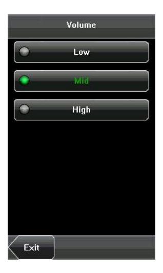
This parameter is used to adjust the volume of voice prompts.
6.1.4 Attendance
This parameter is used to open the attendance function and it displayed 🔯 icon on the initial interface.
6.2 Display Parameters
6.2.1 Language
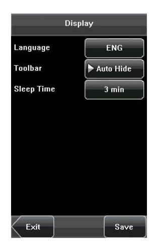
This parameter is used to display the current language used by the device. For multilingual-capable devices, you can switch between different languages (English, Chinese and Traditional Chinese) through this parameter. Then you should restart the device.
6.2.2 Toolbar
This parameter is available for display Shortcut Keys Status on the initial interface when Attendance function is enabled. User can press [ Auto Hide ] or [ Unhide ].
If the Attendance function is closed, this parameter function is invalid.
6.2.3 Sleep Time
This parameter is used to specify a period after which the device is put in sleep mode if no operation within this period. You can wake up the device from sleep by pressing any key or touching the screen. Numerical ranges minutes, 3 minutes by default.
6.3 Shortcut Definition
6.3.1 Shortcut Keys Using
Press on the initial interface, and the related status and function keys are displayed on the right corner of the interface for use.
6.3.2 Shortcut Definition Setting
Press [Menu] > [System] > [Shortcut Def.], the user according to need to set up shortcut key for state key.
(1) Press [ Status ], enter the edit screen of the status key, as shown in figure 1 below; press the Label box, enter the Label screen, as shown in figure 2 below; press the row of the label (six options for the status) to change it to the corresponding label; the user can choose the label of the status key according to practical needs.
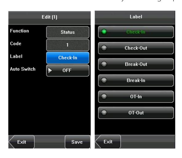
Figure 1 Figure 2
Tip: The Code cannot be modified; it is changed accordingly with the selected label of the status key.
(2) Select [On] in Auto switch, then press [Define], the figures are as shown in figure 1 and figure 2 below.
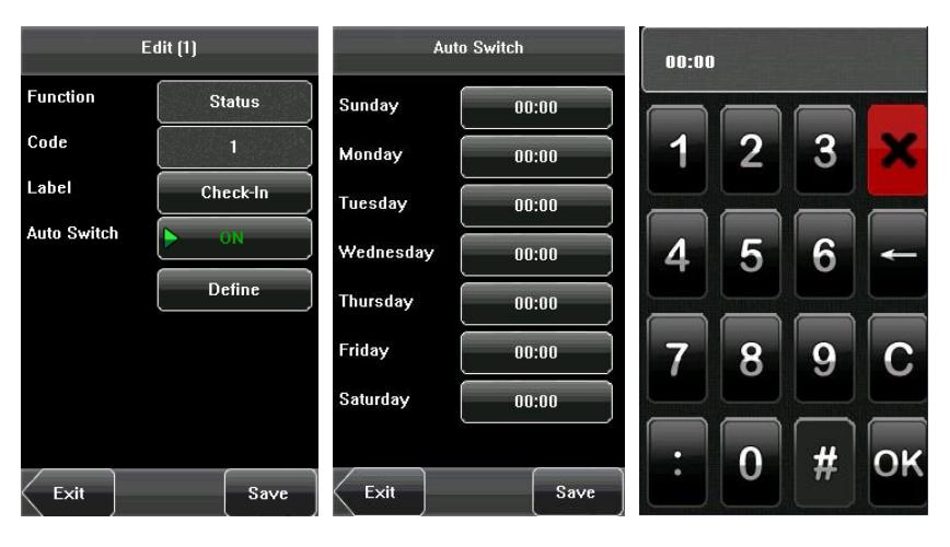
Figure 1 Figure 2 Figure 3
(3) Press the time box after [ Sunday ], set the time, as shown in figure 3 above. Press [ OK ] to save and return to the edit screen. Press [ Save ] to save the setting.
6.4 Access Control Parameters
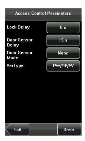
You can press [Menu] > [System] > [Access Control Parameters] to set the parameters of the Lock Delay, Door Sensor Delay, Door Sensor Mode, Verification Type.
6.4.1 Lock Delay
The time duration of electronic lock works from open to close when user's verification succeeds (In case the door is closed).
"S (second)" is chosen as the unit of lock driver duration, and you can set it s.
If set the duration to , means Lock driver duration is closed. Normally, we do not suggest set it to .
6.4.2 Door Sensor Delay
Indicates the delay for checking the door sensor after the door is opened. If door sensor state is inconsistent with the normal state set by the door sensor switch, an alarm will be triggered, and this period of time is regarded as the Door Sensor Delay . (Value scope: 1 ~ 99 seconds)
6.4.3 Door Sensor Mode
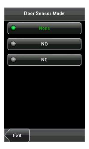
Includes the None, Normally Open (NO), and Normally Closed (NC) modes. None indicates that the door sensor switch is not used. NO indicates that the door sensor is open in the normal state. NC indicates that the door sensor is closed in the normal state.
6.4.4 Verification Type
The device supports various Verification Types: Password or ID Card (PW/RF), Password Only (PW), Card Only (RF), Password plus ID card (PW&RF).
User can choose the verification type which your need. The paths: [Menu] > [System] > [Access Control Parameters] > [VerType].
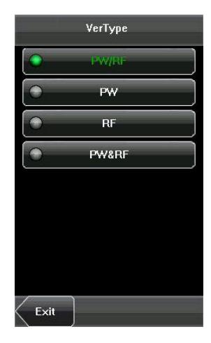
Tip: When the device is connected to a reader, if the verification type of the reader is PW&RF, then the verification type of the device should be PW&RF; if the reader without keyboard, that is to say, the verification type of the reader is card only, then the verification type of the device should be PW/RF or RF.
6.5 Update
You can upgrade the device firmware by using the upgrade file in the USB disk through this function.
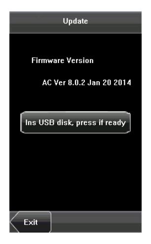
If you need the firmware upgrade file, please contact our technical support personnel. Generally the firmware upgrade is not recommended.
7. Data Management
Through the [ Data Mgt. ] menu, you can perform management of data stored on the device, for example, delete all data, clear administrator, restore the device to factory settings.
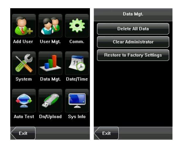
Delete All Data: Delete all the information of enrolled personnel, including their ID card and Password records.
Clear Administrator: Change all administrators to ordinary users.
Restore to Factory Settings: Restore all parameters on the device to factory settings.
Tip: The employee information records will not be deleted during restoration to factory settings.
8. Date/Time Setting
The date and time of the device must be set accurately to ensure the accurately of attendance time.
- 1. Press [Menu] on the initial interface to display the main menu interface.
- 2. Press [Date/Time] on the main menu interface to display the time setting interface.
- 3. Input the desired date and time by pressing the parameter.
- 4. Press [Save] to save the current information and return to the previous interface. Press [Exit] to return to the previous interface without saving the current information.
9. Auto Test
The auto test enables the system to automatically test whether functions of various modules are normal, including the Test Screen, Voice, Time and Calibration.
9.1 Test Screen
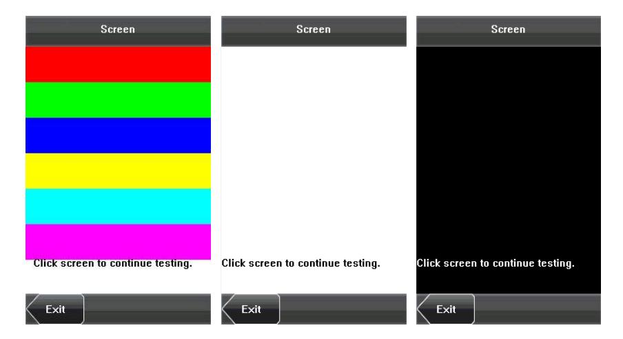
The device automatically tests the display effect of the color TFT display by displaying full color, pure white and pure black and checks whether the screen displays properly. You can continue the test by touching the screen or exit it by pressing [Exit].
9.2 Test Voice
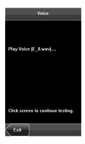
The device automatically tests whether the voice files are complete and the voice quality is good by playing the voice files stored in the device. You can continue the test by touching the screen or exit it by pressing [Exit].
9.3 Test Time
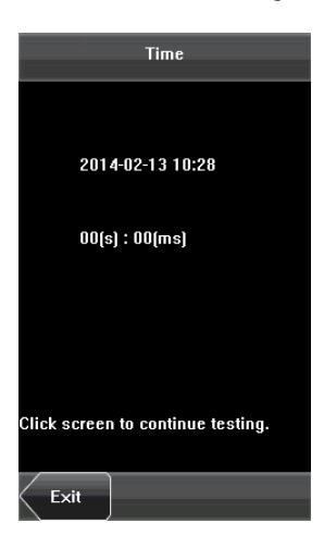
The device tests whether its clock works properly by checking the stopwatch of the clock. Touch the screen to start counting, and touch it again to stop to check whether the counting is accurate. Press [ Exit ] to exit the test.
9.4 Screen Calibration
You can perform all the menu operations by touching the screen with one of your fingers or a touch pen. When the touch screen is less sensitive to the touch, you can perform a screen calibration through menu operations.
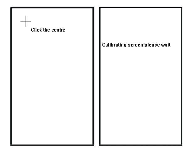
The Screen Calibration Operation:
- (1) Press [Menu] on the initial interface to display the main menu interface.
- (2) Press [Calibration] on the [Auto Test] interface to display the screen calibration interface.
- (3) Touch the center of the cross [+].
- (4) Repeating step 3 following the move of the [+] icon to different locations on the screen.
- (5) Touch the center of the cross at five locations on the screen correctly. When the message "Calibrating screen, please wait..." is displayed on screen, the calibration succeeds and the system automatically returns to the main menu. If the calibration fails, the system recalibration will start from Step 3.
10. USB Disk Management
Through the [ Dn/Upload ] menu, you can download user information and attendance data stored in a USB disk to related software.
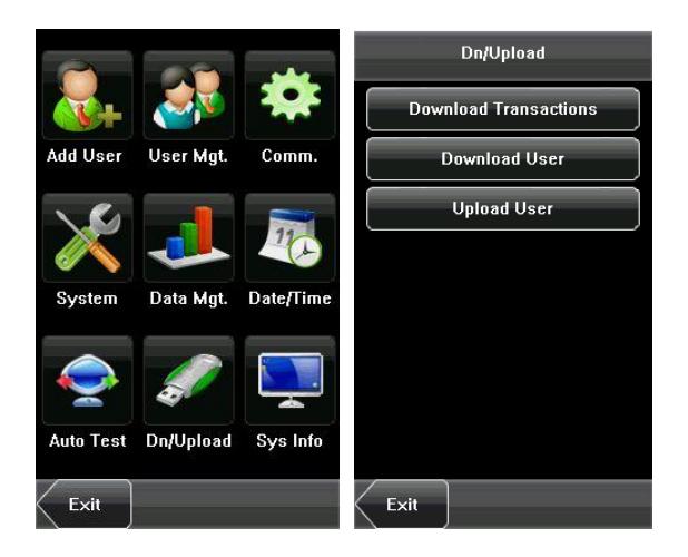
Download Transactions : Download attendance data from the device to a USB disk.
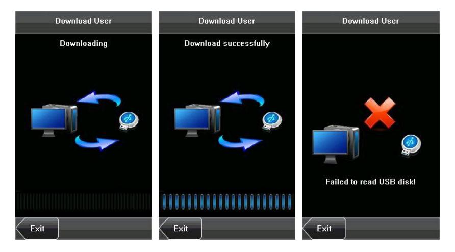
Download User . Download all the user information from the device to a USB disk.
Upload User . Upload the user information stored in a USB disk to the device.
11. System Information
You can check the storage status and version information of the device through the [Sys Info] option.
Records: The numbers of Access Control Records and enrolled users are displayed on the [ Records ] interface; the total storage capacity and occupied capacity are graphically displayed graphically.
Card Capacity: 30000
Records Capacity: 100000
Device: The device name, serial number, MAC Address, vendor, manufacture time and firmware version information are displayed on the [ Device ] interface.
12. Appendix
12.1 T9 Input Instruction
The device supports to input English characters, numbers and symbols. Press related button to input text. For example, press [ Name ] to display the text input interface, as shown in the figure:
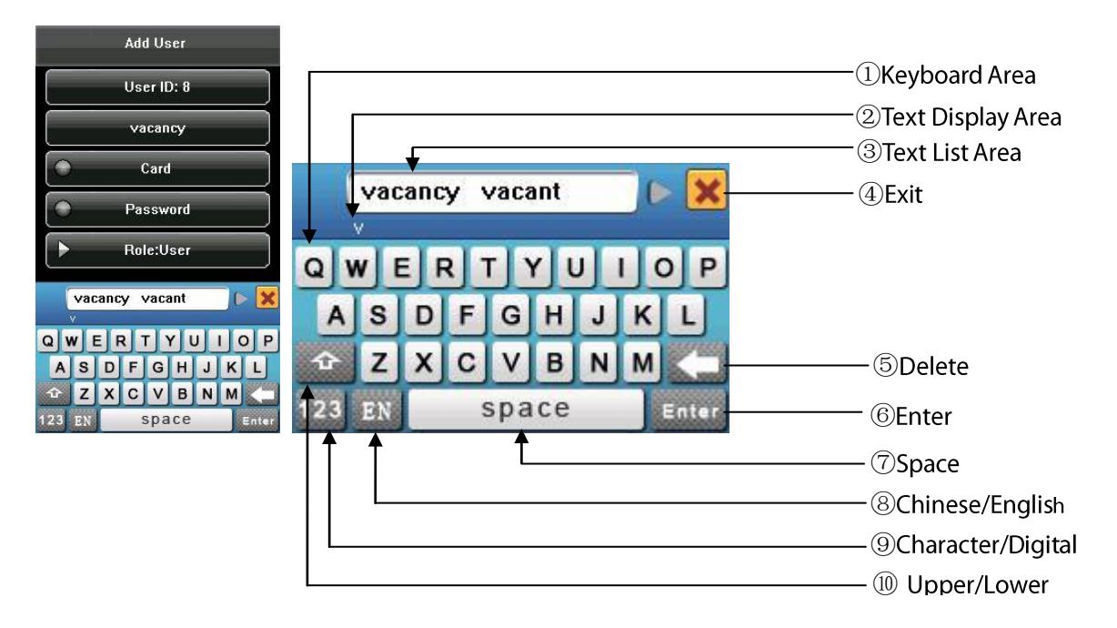
To enter a name, proceed as follows:
- 1. Press [Name] on the [Add User] interface, as shown in figure below.
- 2. Enter the letter characters, and a list of characters in relation to the letter is presented in the text display area.
- 3. If the desired character is displayed in the text display area, press this character or press [ Enter ]. And this character is at the same time displayed on the [ Name ] button. Enter next character by repeating Step2.
- 4. After finishing the entry of name, press [X] to exit the keyboard interface and return to the previous interface.
12.2 USB
1. USB Host
The devices may be used as USB host to exchange data with external U-disk. The data transmission speed is quick, the traditional product only supports the Ethernet way for data transmission, when as a result of physical condition limit, data quantity big, and the data transmission cost quite long time. But the USB data transmission is quicker than any of the former transmission mode, may complete downloading data by U disk in a short period of time, like this greatly enhances the efficiency.
2. USB Client
The product will be as removable storage devices, the data in the device will be transferred to a PC via connectedly USB cable.
When the device is as a USB Client, the device communication settings menu will have USB communications options. Please refer to 5. Communication Setting for details.
12.3 Introduction of Wiegand
Wiegand26 is an access control standard protocol established by the Access Control Standard Subcommittee affiliated to the Security Industry Association (SIA). It is a non-contact IC card reader interface and output protocol.
Wiegand26 defines the interface between the card reader and controller used in the access control, security and other related industrial fields. Wiegand26 helps standardize the work of the card reader designers and controller manufacturers. The access control products manufactured by our company are also designed by following this protocol.
Digital Signals
The figure below is a sequence diagram in which the card reader sends digital signals in bit format to the access controller. In this sequence diagram, Wiegand follows the SIA's access control standard protocol for the 26-bit Wiegand card reader (one pulse time ranges between 20 us and 100 us, and the pulse jump time ranges between 200us and 20ms). Data1 and Data0 are high level (larger than Vol) signals till the card reader prepares to send a data stream. The asynchronous low-level pulse (smaller than Vol) generated by the card reader is sent to the access control panel (The saw-tooth wave as shown in Figure below) through Data1 or Data0. Data1 and Data0 pulses will neither overlap nor be generated synchronously. The table below lists the maximum and minimum pulse width (a consecutive pulse) and pulse jump time (time between pulses) allowed by the F series finger vein access control device.
Figure: Sequence Diagram
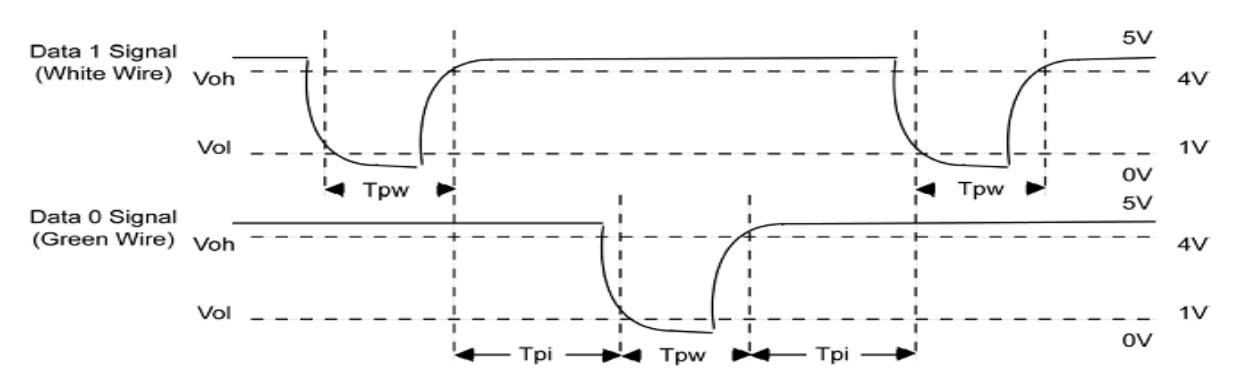
Table: Pulse Time
| Symbol | Definition | Typical Value of Reader |
|---|---|---|
| Tpw | Pulse Width | 100 μs |
| Трі | Pulse Interval | 1 ms |
12.3.1 Wiegand 26-bits Output Description
The system has a built-in Wiegand 26-bits format.
The composition of the Wiegand 26-bits format contains 2 parity bits and 24 bits for output contents ("User ID" or "Card Number"). The binary code of 24-bits represent up to 16,777,216 (0~16,777,215) different values.
| 1 | 2 | 25 | 26 |
|---|---|---|---|
| Even Parity Bit | User ID/Card | d Number | Odd Parity Bit |
Definition of Fields:
| Field | Meaning |
|---|---|
| Even Parity Bit | Judged from bit 2 to bit 13. The even parity bit is 0 if the character has an even number of 1 bit; otherwise, the even parity bit is 1. |
| User ID/ Card Number | User ID/Card Number (Card Code, 0~16777215) |
| (bit 2~bit 25) | Bit 2 is the Most Significant Bit (MSB). |
| Odd Parity Bit | Judged from bit 14 to bit 25. The odd parity bit is 1 if the character has an even number of 1 bit; otherwise, the odd parity bit is 0. |
For example , for a user with the user ID of 12345, the enrolled card number is 0013378512 and the failed ID is set to 1.
1. When the output is set to "User ID", the Wiegand output is as follows upon successful verification:

Even parity bit User ID = Binary code of 12345 Odd parity bit
2. When the output is set to "Card Number", the Wiegand output is as follows upon successful verification:

Even parity bit User ID = Binary code of 0013378512 Odd parity bit
3. The Wiegand output is as follows upon verification failure:

Even parity bit Failed ID = Binary code of 1 Odd parity bit
Fig: If the output contents exceed the scope allowed for the Wiegand format, the last several bits will be adopted and first several bits are automatically discarded. For example, the user ID 888 888 888 is 110 100 111 110 110 101 111 000 111 000 in binary format. Wiegand 26 only supports 24 bits, that is, it only outputs the last 24 bits, and first 6 bits "110 100" are automatically discarded.
12.3.2 Wiegand 34-bits Output Description
The system has a built-in Wiegand 34-bits format. Press [Wiegand Format], and select "Standard Wiegand 34-bits".
The composition of the Wiegand 34-bits format contains 2 parity bits and 32 bits for output contents ("User ID" or "Card Number"). The binary code of 32-bits represent up to 4,294,967,296 (0-4,294,967,295) different values.
1 2 33 34 User ID/Card Number Odd Parity Bit Even Parity Bit
Table 2 Definition of Fields
| Field | Meaning |
|---|---|
| Even parity bit | Judged from bit 2 to bit 17. The even parity bit is 0 if the character has an even number of 1 bit; otherwise, the even parity bit is 1. |
| User ID/Card Number | User ID/Card Number (Card Code, 0~4,294,967,295) |
| (bit 2-bit 33) | Bit 2 is the Most Significant Bit (MSB). |
| Odd parity bit | Judged from bit 18 to bit 33. The odd parity bit is 1 if the character has an even number of 1 bit; otherwise, the odd parity bit is 0. |
For example, for a user with the user ID of 123456789, the enrolled card number is 0013378512 and the failed ID is set to 1.
1. When the output is set to "User ID", the Wiegand output is as follows upon successful verification:

Even parity bit
User ID = Binary code of 123456789
Odd parity bit
2. When the output is set to "Card Number", the Wiegand output is as follows upon successful verification:

3. The Wiegand output is as follows upon verification failure:

12.3.3 Wiegand Customize Wiegand Format Description
To customize Wiegand format, proceed as follows:
- (1) Select [User Define Format] and the [Define] key is then enabled.
- (2) Press [Define] to display the [User Define Format] interface, as shown in the following figure:
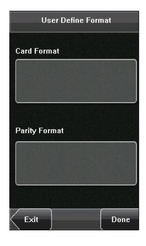
(3) Press the entry box below "Card Format" to display the following interface:
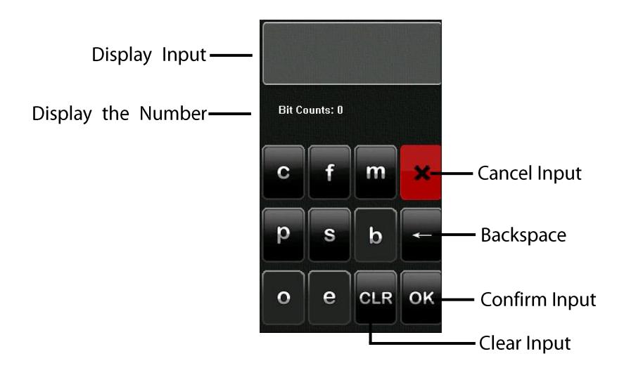
Characters used to define Card Format bits and their meanings:
c: Indicates the card number, that is, the output contents, it can be set to User ID/Card Number through menu operations.
f: Indicates the facility code which is 0 by default. It is not configurable. To modify it, please contact the equipment supplier.
m: Indicates the manufacturer code which is 0 by default. It is not configurable. To modify it, please contact the equipment supplier.
p: Indicates the parity position.
- s: Indicates the site code which can be set from 0 to 255 by default.
- (4) Click the entry box below "Parity Format" to display the following interface:
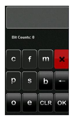
Characters used to define Parity Format bits and their meanings:
- o: Indicates the odd check, that is, there is an odd number of 1's in the bit sequence (including one parity bit). For example, for 1000110(0), the parity bit is 0 and there are already three 1's. After 0 is suffixed to 1000110, there is still an odd number of 1's.
- e: Indicates the even check, that is, there is an even number of 1's in the bit sequence (including one parity bit). For example, for 1000110(1), the parity bit is 1 and there are already three 1's. After 1 is suffixed to 1000110, there is an
even number of 1's.
b: Indicates both odd check and even check.
For example, Definitions of several universal Wiegand formats.
Wiegand34
Card Format bits:
pccccccccccccccccccccccccccccccccc
Parity Format bits:
eeeeeeeeeeeeeooooooooooooo
Exip: Wiegand34 consists of 34 bits. The first bit is the even parity bit of bits 2 to 17; the 34th bit is the odd parity bit of bits 18 to 33; the second to the ninth bits are the site code; the 10th to the 25th bits are the card number.
Wiegand37a
Card Format bits: pmmmmsssssssssscccccccccccccc
Parity Format bits: oeobeobeobeobeobeobeobeobeobeo
Tip: Wiegand37a consists of 37 bits. The first bit is the odd parity bit of bits 3, 4, 6, 7, 9, 10, 12, 13, 15, 16, 18, 19, 21, 22, 24, 25, 27, 28, 30, 31, 33, 34 and 36; the 37th bit is the odd parity bit of bits 2, 4, 5, 7, 8, 10, 11, 13, 14, 16, 17, 19, 20, 22, 23, 25, 26, 28, 29, 31, 32, 34 and 35; bits 4, 7, 10, 13, 16, 19, 22, 25, 28, 31 and 34 participate in both odd and even parity check. Bits 2 to 5 are manufacturer code; bits 6 to 17 are the site code; bits 18 to 36 are the card number.
Wiegand37
Card Format bits:
pmmmffffffffsssssscccccccccccc
Parity Format bits:
eeeeeeeeeeeeeeooooooooooooooo
Fig: Wiegand37 consists of 37 bits. The first bit is the even parity bit of bits 2 to 18; the 34th bit is the odd parity bit of bits 19 to 36; the second to the fourth bits are the manufacturer code; the 5th to the 14th bits are facilitate code; the 15th to the 20th bits are the site code; the 21th to the 36th bits are the card number.
Wiegand50
Card Format bits: psssssssssssssssssscccccccccccccccccc
Parity Format bits:
Fig: Wiegand50 consists of 50 bits. The first bit is the even parity bit of bits 2 to 25; the 50th bit is the odd parity bit of bits 26 to 49; the second to the 16th bits are the site code; the 17th to the 49th bits are the card number.
12.4 Anti-Pass Back
[Overview]
Sometimes, some illegal people follow the other one into the gate, which will cause the security problems. To prevent such risks, this function is enabled. The In record must match the Out record, or the gate won't open.
This function needs two machines or a machine with a reader to work together.
Anti-pass back between two machines:
One is installed inside of the door (master machine hereinafter), the other is installed outside of the door (slave machine hereinafter). Wiegand signal communication is adopted between the two machines.
Anti-pass back between a machine with a reader:
The machine is installed inside of the door (master machine hereinafter), the reader is installed outside of the door (slave machine hereinafter). Wiegand signal communication is adopted between the machine with the reader.
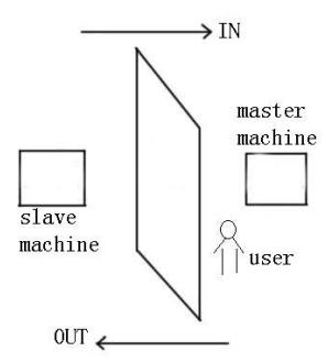
[Working principle]
The master machine has Wiegand In and slave machine has Wiegand Out functions. Connect Wigand Out of slave machine to Wiegand In of master machine. Wiegand output from slave machine must not own machine ID. The number sent to master machine from slave machine must be found in the master machine.
[Function]
Judge whether it is anti-pass back according to user's recent in-out record. In record and out record must be matched. This machine supports out, in, or out-in anti-pass back.
When the master machine is set as "out anti-pass back", if user wants to come in and go out normally, his recent record must be "in", or he cannot go out. Any "out" attempt will be refused by "anti-pass back" function. For example, a user's recent record is "in", his second record can be "out" or "in". His third record is based on his second record. Out record and in record must match. (Notice: If customer has no record before, then he can come in but cannot go
out).
When the master machine is set as "in anti-pass back", if the user wants to come in and go out normally, his recent record must be "out", or he cannot go out. Any out record will be "anti-pass back refused" by the system. (Notice: If the customer has no former record, then he can go out, but cannot come in).
When the master machine is set as "out-in anti-pass back", if the user wants to come in and go out normally, if his recent record is "out" and "in", then his next record must be "in" and "out".
[Operation]
1. Select model
Master machine : The machine with Wiegand in function, except for F10 reader.
Slave machine : The machine with Wiegand Out function.
2. Menu setting
Anti-pass back
There are four options: in/out anti-pass back, out anti-pass back, in anti-pass back, and none.
Out anti-pass back: Only user's last record is in-record, can the door be open.
In anti-pass back: Only user's last record is out-record, can the door be open.
Device status: There are three options: Control-in, control-out and none
Control-in: When it is set, the verified records on the device are in-records.
Control-out: When it is set, the verified records on the device are out-records.
None: When it is set, close the device's anti-pass back function.
3. Modify device's Wiegand output format
When the two devices are communicating, only the Wiegand signals without device ID are received. Enter device menu > communication option > Wiegand option or enter software > basic setting > device management > Wiegand, to modify "defined format" as "wiegand 26 without device ID".
4. Enroll user
The user must be on master machine and slave machine at the same time, and user PIN must be the same. Therefore, it is necessary to enroll user on master machine and slave machine at the same time.
5. Connection instruction
Wiegand communication is adopted for master machine and slave machine. Refer to the following for connection:
| Master | Slave | |
|---|---|---|
| IND0 | <> | WD0 |
| IND1 | <> | WD1 |
| GND | <> | GND |
12.5 Environment-Friendly Use Description

The Environment Friendly Use Period (EFUP) marked on this product refers to the safety period of time in which the product is used under the conditions specified in the product instructions without leakage of noxious and harmful substances.
The EFUP of this product does not cover the consumable parts that need to be replaced on a regular basis such as batteries and so on. The EFUP of batteries is 5 years.
Names and Concentration of Toxic and Hazardous Substances or Elements Toxic and Hazardous Substances or Elements Parts Name Pb Hg Cd Cr6+ PBB PBDE Chip resistor 0 X 0 0 0 0 Chip × 0 0 0 0 0 capacitor Chip inductor Chip diode 0 0 0 0 0 ESD components Buzzer X 0 0 0 0 0 Adapter X Screws X
x: Indicates that this toxic or hazardous substance contained in at least one of the homogeneous materials for this part is above the limit requirement in SJ/T11363-2006.
Fip: 80% of the parts in this product are manufactured with non-hazardous environment-friendly materials. The hazardous substances or elements contained cannot be replaced with environment-friendly materials at present due to technical or economical constraints.
o: Indicates that this toxic or hazardous substance contained in all of the homogeneous materials for this part is below the limit requirement in SJ/T11363-2006.