ZKTeco USA EC10 Quick Start Guide
Open the original PDF document
View PDFEC10 & EX16 Quick Start Guide
Version: V1. 1 Date: 2013. 7
1. Installation Precautions
-
Pay attention to the following safety items. Mis-operations may cause human danger or equipment faults:
- 1) Before installation completes, do not power on the equipment or perform operations with electricity.
- 2) Use dedicated elevator ethernet cable to connect the elevator controller and computer. Use 2pin controller cable for the press button on each floor.
- 3) Install the card reader with a height of 1.2 to 1.4 meters.
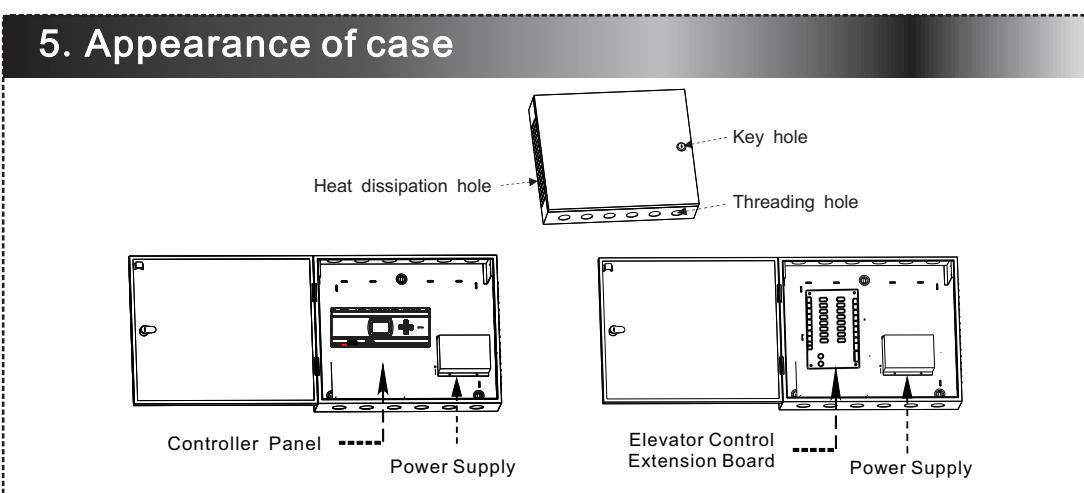
- 4) Install the elevator main controller and expansion board on the elevator lift car.
- 5) Install the emergency button in the management center or under the elevator button.
2. System Introductions
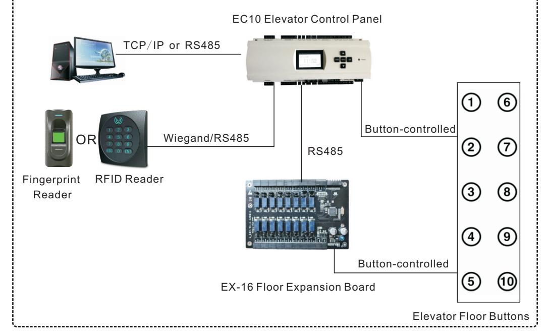
The EC10 prevents unauthorized elevator-users from accessing pre-defined restricted floors in the building. The EC10 (Elevator Control panel) controls access up to 10 floors. Also available is the EX16 (Elevator Floor Expansion board) which allows for access control of up to 16 additional floors. A maximum three EX16 boards can be daisy-chained together and collectively control access of up to 58 floors. In order to gain access to a desired floor, authorized users must first present either a valid fingerprint and/or RFID card when entering the elevator. For example, if an authorized user has access rights to only floor ③ and floor ⑩, the elevator will not move if that same user presses the elevator button for floor ④.

4. EX 16 DIP Switch Settings
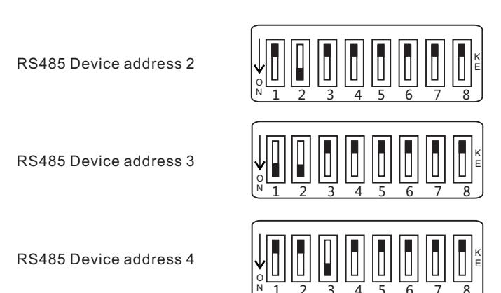
DIP switches 2-4 are used to set each EX16 Floor Extension Board's unique device address using RS485 communication. Please keep the EX16 powered off before setting the device address. Each device address needs to be unique. See example below:
8. EC10 Wiring Terminals Connection
Notes:
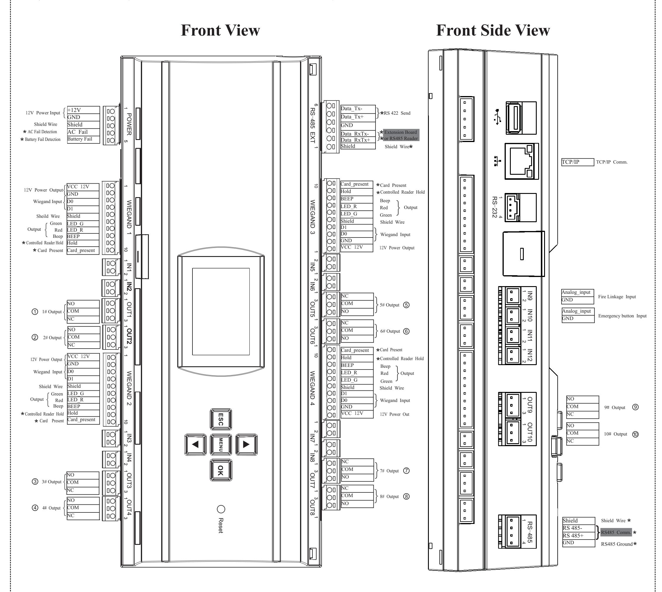
- 1) The backup input is reserved for the elevator control system.
- 2) Fire linkage and emergency button function require no software settings. These functions are available when the hardware is installed.
- 3) GPRS, WIFI and functions marked by * are optional. If these functions are required, contact our business representatives or pre-sale technical support.
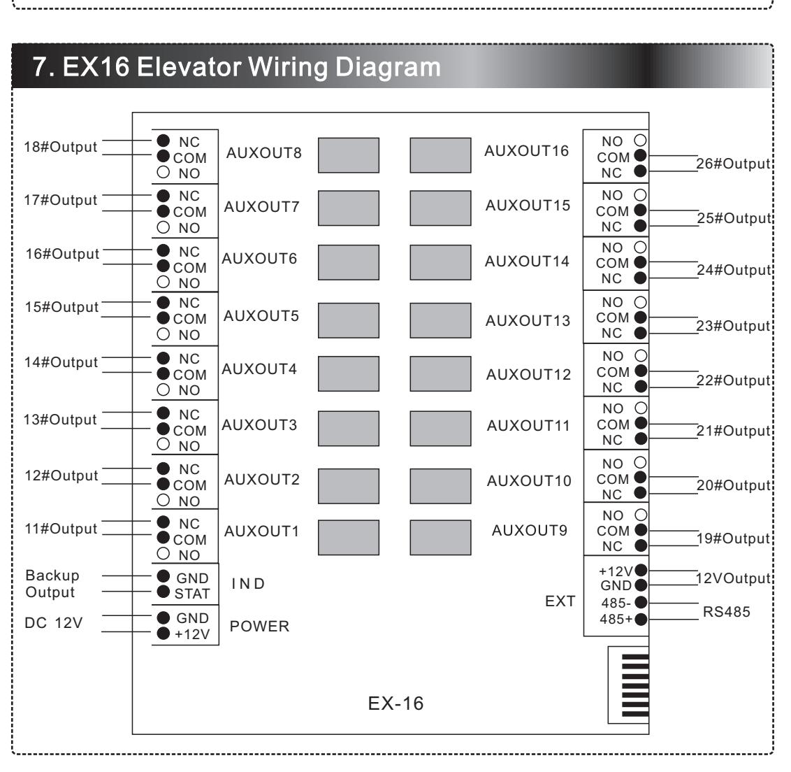
- 4) "#" indicates floor, "1# output" indicates that it is connected to the first floor button, the first expansion board is connected to the 11th floor button.
Notice:
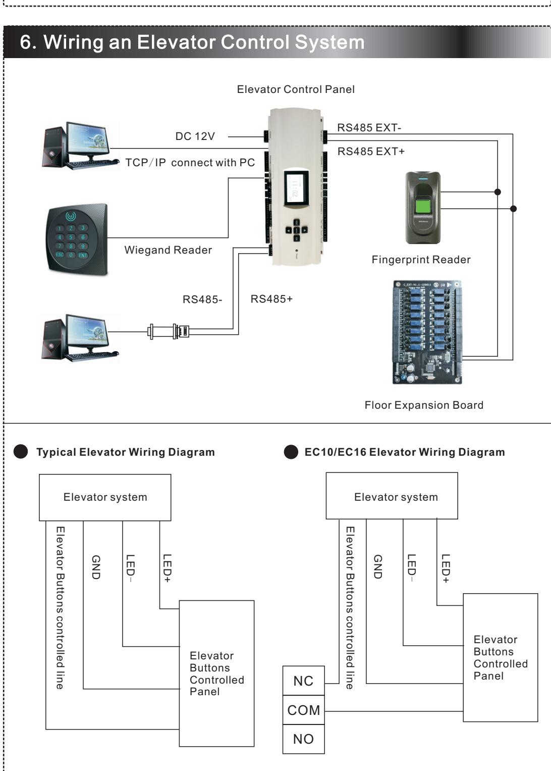
- 1. Open the elevator press button panel when connecting to the elevator button. Ask the supplier to provide the floor button control circuit. If the supplier can not provide the circuit, exclude the incorrect circuit one by one and ensure the correct connections.
- 2. EC10 connects to the computer using TCP/IP or RS485.
- 3. EC10 supports ZK fingerprint readers (model FR1200) and RFID card readers (model KR series).
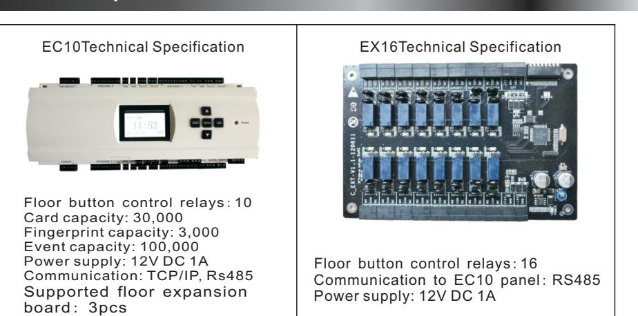
- 4. EC10 controls access up to 10 floors, EX16 controls access up to 16 floors. An EC10 carries a maximum of 3 expansion boards. Total 58 floors can be controlled when combining EC10 with EX16.
- 6. Wiegand reader can connect to the elevator main controller Wiegand 1#~ 4#.
- 7. IN9 functions as fire linkage signal input. When fire linkage signal works, elevator control system stops working and the elevator retains to original status. (Fire linkage must be passive dry contact signal)
- 8. IN10 functions as an emergency button. When it is pressed, the whole elevator is not controlled by elevator controller. At this moment, up and down buttons are available. When the emergency button is not pressed, the elevator retains to the original status.
- 9. ①~⑩ Output terminals connect to floor press button.