Von Duprin Maintenance Kit Manual 109277
Open the original PDF document
View PDF

941079-00
Maintenance Kit
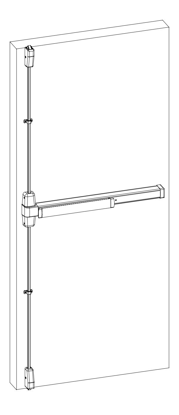
Table of Contents
| Description: | Page Number: |
|---|---|
| Pictorial Index to Parts (immediatey follows "Table of Con | tents")PIP-1, PIP-2 |
| 1. Center Case Parts | |
| Insert-98/99 One Piece Cover | 1-1 |
| NL Drive Screw-98/99 Device | 1-2 |
| Control Link Pin-Touch Bar Device | 1-2 |
| Tailpiece Guide | 1-3 |
| 2. Dogging Assembly Parts | |
| Hex Dogging Replacement Kit | 2-1 |
| Hex Dogging Shaft | 2-1 |
| Dogging Adapter Spring | 2-2 |
| Dogging Spring | 2-3 |
| Cylinder Dog Actuator | 2-4 |
| CD Dogging Plug | 2-4 |
| 3. Mechanism Case Parts | |
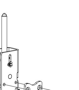
| Mechanism Case Mounting Bracket | 3-1 |
| Anti-Rattle Spring-33/35/98/99 | 3-2 |
| Cover Plate Stop | 3-2 |
| Shock Absorber and Holder Assembly | |
| Pushbar Guide (front) | |
| Pushbar Guide (rear) | |
| 4. Vertical Rod Parts | |
| Rod Extension Connector | 4-1 |
| Extension Rod DrillTemplate-2227/98/9927 | |
| 98/9927 Rod Guide Assembly | |
| 1/8 x 7/16 Roll Pin | |
| 5. Surface Vertical Latch Parts | |
| 299 Strike Shim | 5-1 |
| Shim-264/299F/499F Strike | |
| Bolt Return Spring | |
| 98/9927 Auxiliary Bolt Spring |
Table of Contents (continued)
| Description: | Page Number: |
|---|---|
| 6. Concealed Vertical Latch Parts Ratchet Lever Spring#10 External Tooth Lock Washer Compression Spring-33/3547 | 6-2 |
| 7. Mounting Hardware, Screws, and Retaining Rings 325 Sex Bolt Asembly 425 Sex Bolt Asembly 10-12 x 10-24 x1 PTHCS 10-24 x 3/4 PPHMS 10-24 x 1PPHMS 8-32 x 1/4 UFPHMS 10-24 x 3/4 UFPHMS 1/4-20 x 3/4 UFPHMS 8-18 x 1/2 UFPHSMS 12-24 Mechanism Case Screw Truarc Retaining Ring T5304-18 10-32 x 1/4 UFPHMSwith Nylock 10-24 x 3/4 FPHMS | 7-1 7-2 7-2 7-3 7-3 7-4 7-4 7-5 7-5 7-6 7-7 |
| 8. Trim Parts Shear Pin Cylinder Retaining Cup. 992L LiftSpring Hex Stud-994/996 Trim. 1/4-20 Hex AStud 10-24 x 1 3/8PPHMS Truarc Retaining Ring 5160-42 Wave Spring Washer. 1/4-20 x 5/8 SocketSet Screw |
8-2
8-2 8-3 8-3 8-4 8-4 8-4 |
| Appendix A: Device Lubrication | A-1 |
| Appendix B: Latch Lubrication | B-1 |
| Index by Part Number | IPN-1, IPN-2 |
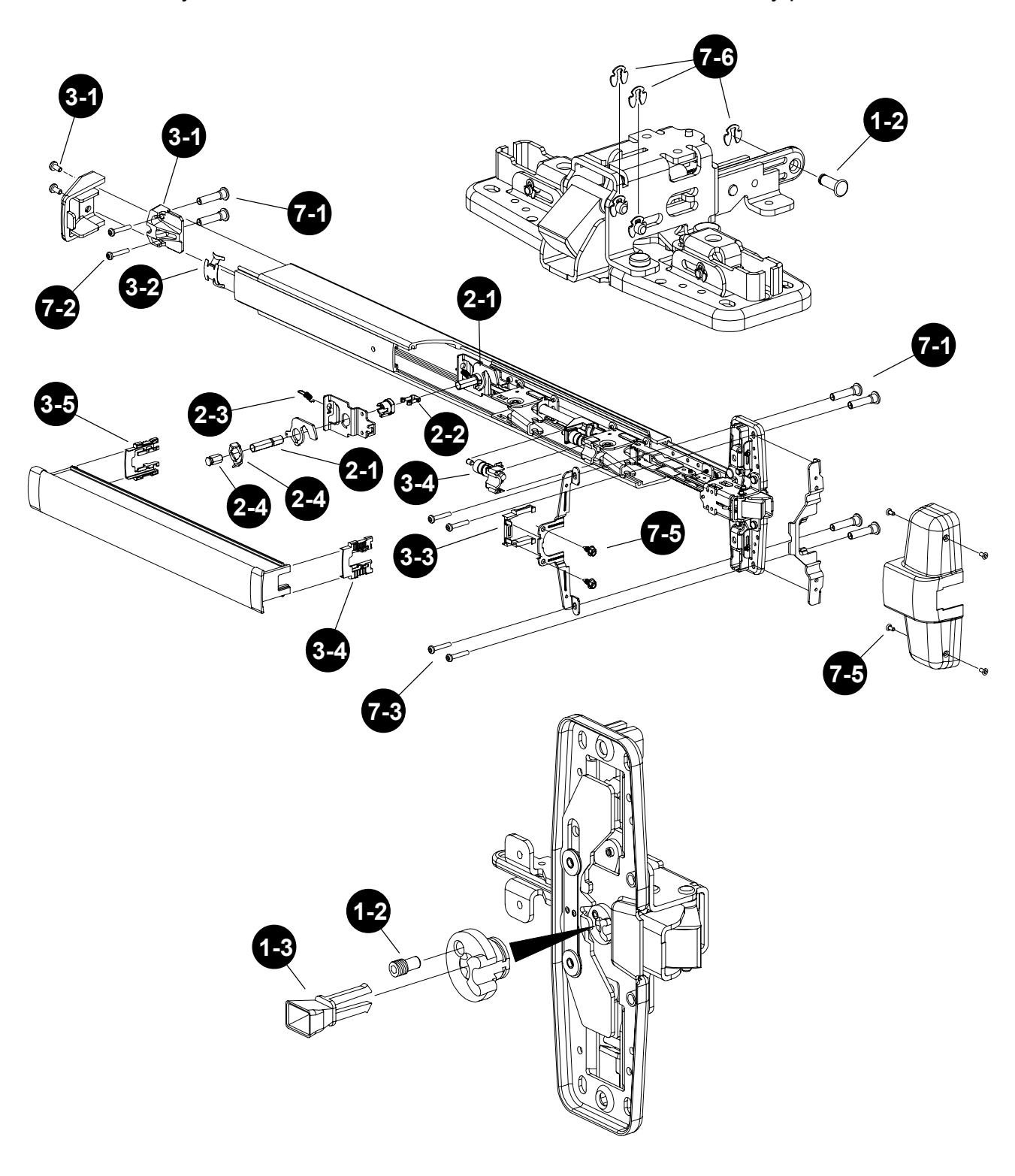
Pictorial Index to Parts
The number in each circle below is the page where information on the part is found. Use the "Table of Contents" to find items by part description. Use the "Index by Part Number" in the back of the manual to find items by part number.
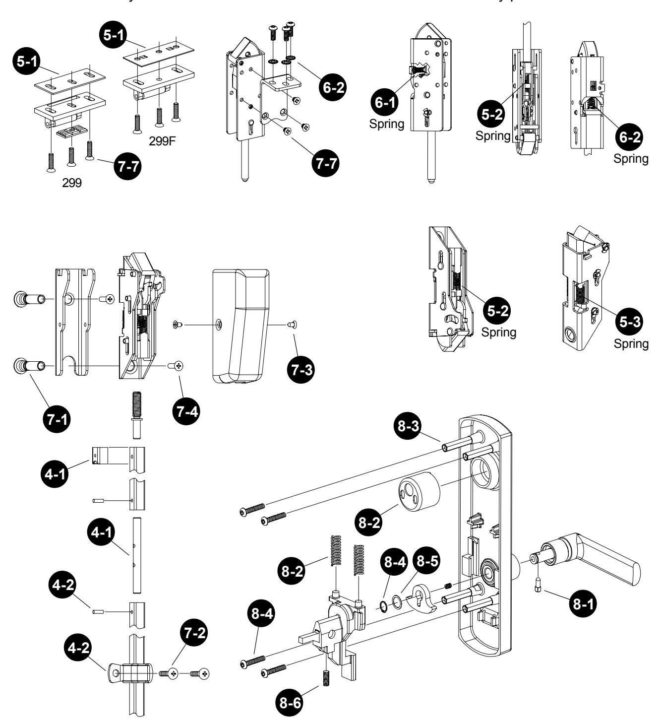
Pictorial Index to Parts (continued)
The number in each circle below is the page where information on the part is found. Use the "Table of Contents" to find items by part description. Use the "Index by Part Number" in the back of the manual to find items by part number.
Page: 1-1
This page is intentionally left blank.
1. Center Case Parts
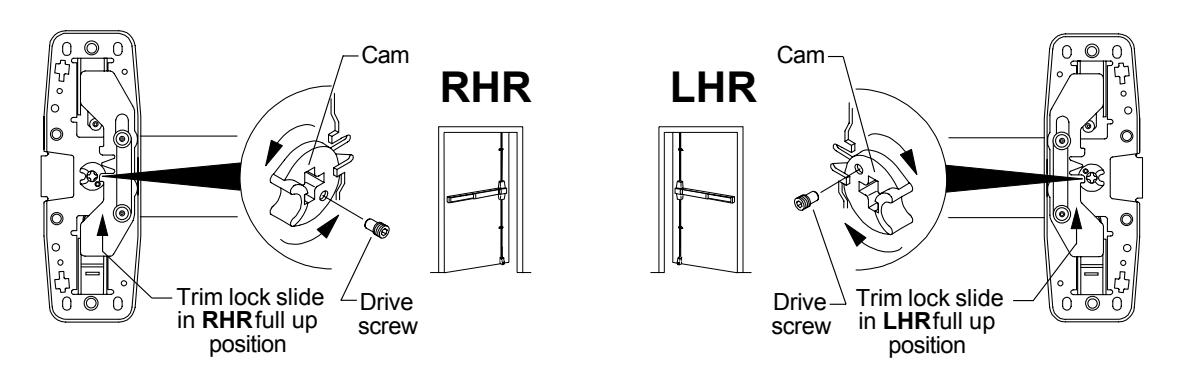
Part Name: NL Drive Screw-98/99 Device Kit Location: Bottom drawer #6
Part Number: 970441-89 unit; 090074-00 bulk, 10/pkg.
Use: 98/99 and 22 devices; BE, EO, DT, NL,
and Rigid applications only
Installation: Use Phillips head screwdriver to turn cam so trim lock slide is in full up position
for RHR or LHR application. Install drive screw in cam using 5/64" hex wrench.
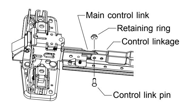
Part Name: Control Link Pin-Touch Bar Device Kit Location: Top drawer #8
Part Number: 090031-00 bulk, 10/pkg.
Use: 98/99, 33/35, and 22 devices
Installation: Align holes of main control link and control linkage. Insert control link pin.
Secure with Truarc retaining ring T5304-18 (090107-00).
1. Center Case Parts
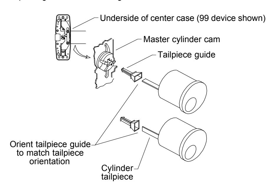
Part Name: Tailpiece Guide Kit Location: Top drawer #18
Part Number: 050156-00 bulk, 10/pkg.
Use: 98/99 and 22 device keyed (rim cylinder)
trim applications
Installation: Snap pronged end of tailpiece guide into cross-slot of master cylinder cam on
underside of center case. Guide cylinder tailpiece into funnel portion of
tailpiece guide when installing trim.
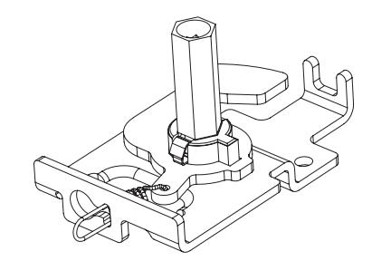
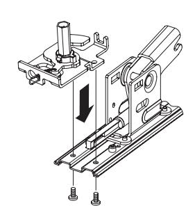
Part Name: Hex Dogging Replacement Kit Kit Location: Top compartment
Part Number: 15-445-00
Use: To replace existing dogging assemblies
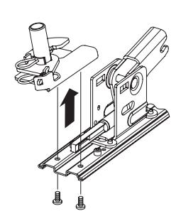
Installation: Remove old dogging assembly, replace with new dogging assembly, and secure
with 2 screws.
Part Name: Hex Dogging Shaft Kit Location: Bottom drawer #5
Part Number: 090040-00 bulk, 2/pkg.
Use: 98/99, 33/35, and 22 dogging assemblies
made after Aug. 1997
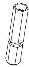
Installation: Insert end of shaft that is closest to groove into dogging adapter. Push down
until shaft snaps into place.

Part Name: Dogging Adapter Spring Kit Location: Bottom drawer #2
Part Number: 090042-00 bulk, 2/pkg.
Use: 98/99, 33/35, and 22 dogging assemblies
made after Aug. 1997
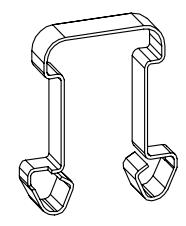
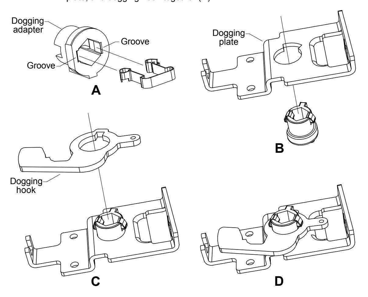
Installation: Pinch legs of spring together and insert into dogging adapter so legs of spring
align with grooves in dogging adapter (A). Insert dogging adapter with spring through bottom of dogging plate (B). Snap dogging hook over protruding end of dogging adapter and legs of spring (C). Spring holds dogging adapter, dogging
plate, and dogging hook together (D).
Part Name: Dogging Spring Kit Location: Bottom drawer #3
Part Number: 090041-00 bulk, 2/pkg.
Use: 98/99, 33/35, and 22 dogging assemblies
made after Aug. 1997
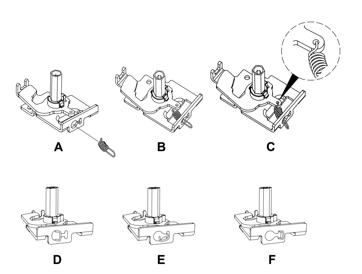
Installation: Hold loop of spring and insert spring through large hole in end of dogging plate
(A and B). Hook short end of spring into hole in dogging hook from top of dogging hook (C). Slide loop of spring from large hole (D) into smaller hole in
end of dogging plate (E) and align loop vertically (F).
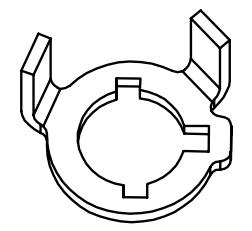
Part Name: Cylinder Dog Actuator Kit Location: Bottom drawer #4
Part Number: 090045-00 bulk, 2/pkg.
Use: 98/99 and 33/35 cylinder dogging assemblies
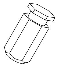
Part Name: CD Dogging Plug Kit Location: Bottom drawer #11
Part Number: 090046-00 bulk, 2/pkg.
Use: 98/99 and 33/35 cylinder dogging assemblies
made after Sept. 1997
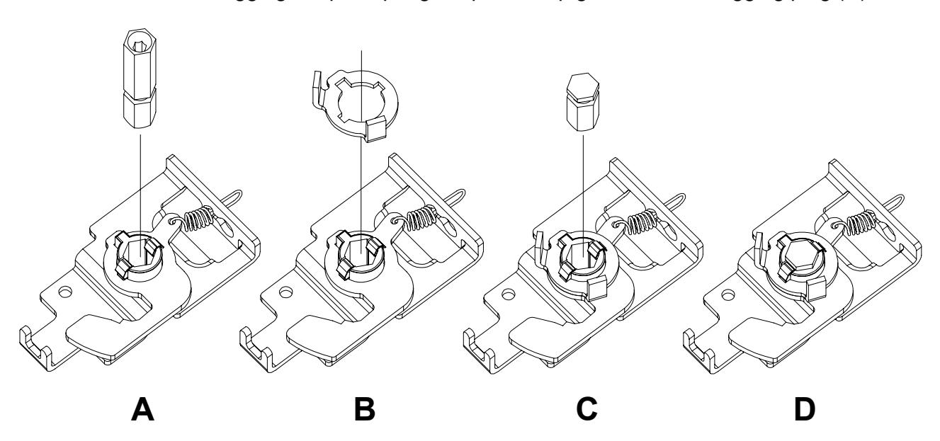
Installation: 1. Pull hex dogging shaft out of dogging adapter (A).
2. Snap cylinder dog actuator into place over dogging adapter spring and dogging adapter (B).
3. Insert CD dogging plug into hex hole in dogging adapter (C) and press until dogging adapter spring snaps into top groove of CD dogging plug (D).
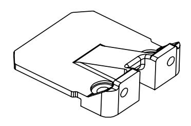
Part Name: Mechanism Case Mounting Bracket Kit Location: Top compartment
Part Number: 050524-00 (unit)
Use: 98/99 and 33/35 devices
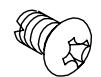
Part Name: End Cap Screw Package Kit Location: Middle 13
Part Number: 900597-00 bulk, 2/pkg.
Use: 98/99 and 33/35 devices
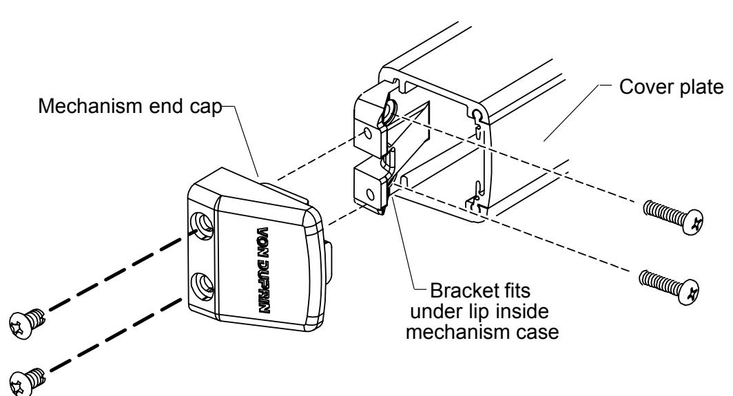
Installation: Slide bracket into mechanism case making sure that Face A is flush against cover plate. Secure bracket to door. Attach mechanism end cap to bracket (end cap covers bracket).
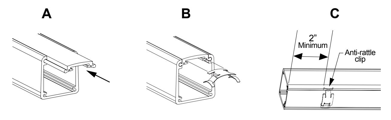
Part Name: Anti-Rattle Spring-33/35/98/99 Kit Location: Top drawer #11
Part Number: 090036-00 bulk, 10/pkg.
Use: 98/99 and 33/35 devices
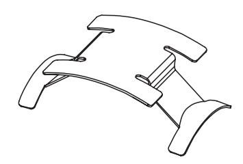
Installation: Without spring, slide cover plate into mechanism case until flush (A and B).
Insert front tabs on spring into channel in underside of cover plate (B). Push spring in and make sure rear tabs also engage channel. Continue pushing spring
in until vertical tabs on back of spring are flush with end of cover plate (C).
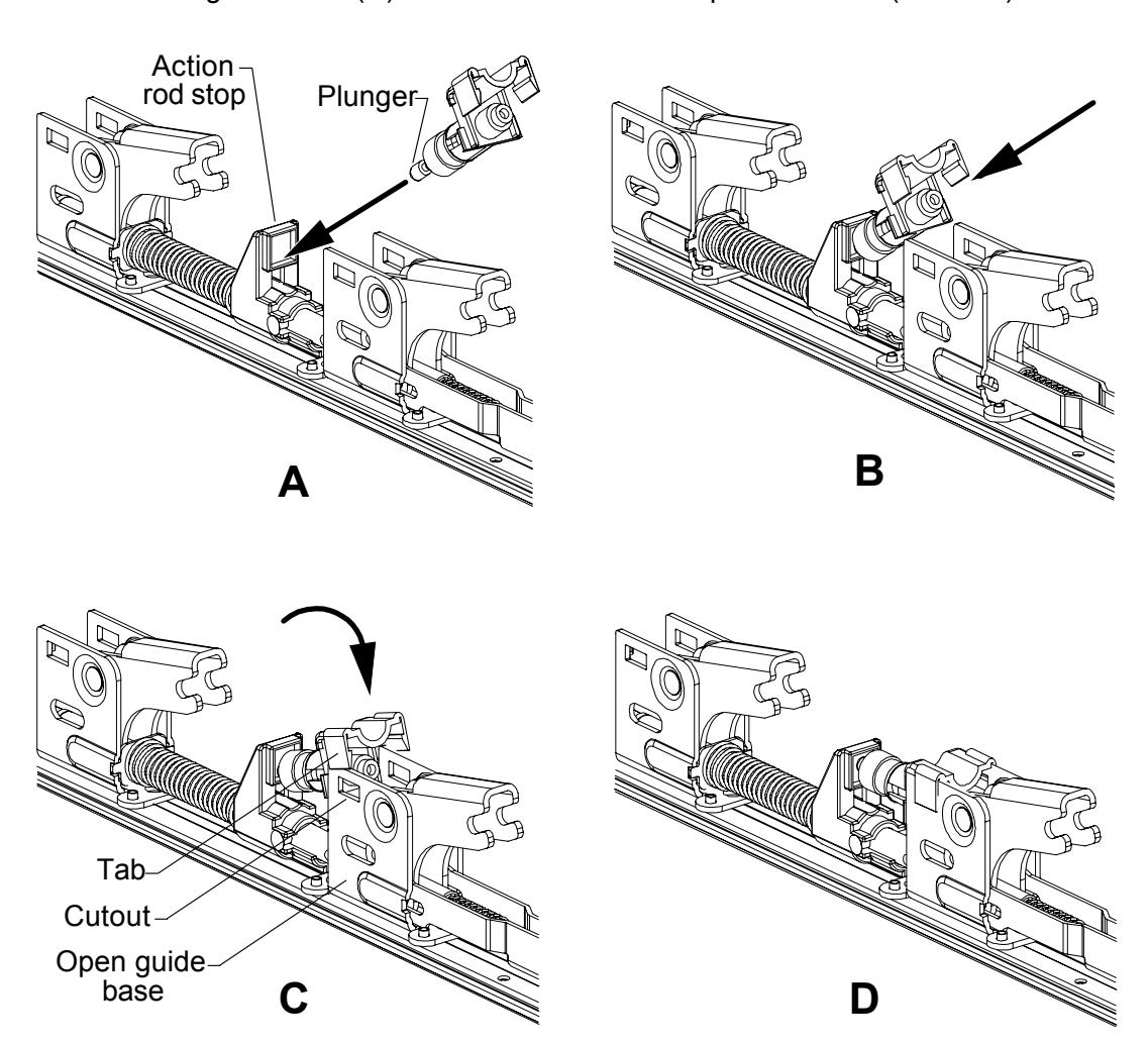
Part Name: Shock Absorber and Holder Assembly Kit Location: Top drawer #17
Part Number: 050491-00 unit
Use: 98/99 and 33/35 devices
Installation: Place tip of plunger against action rod stop (A). Press in until plunger is fully
retracted (B). Rotate shock absorber and holder so tabs slide over top of open
guide base (C). Push down so tabs snap into cutouts (C and D).
Part Name: Pushbar Guide (front) Kit Location: Middle drawer #12
Part Number: 090049-00 bulk, 10/pkg.
Use: 98/99 and 33/35 devices
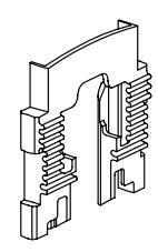
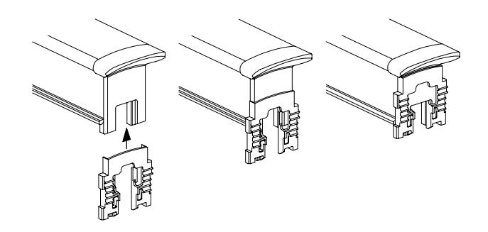
Installation: Remove pushbar from mechanism case. Slide pushbar guide onto front of
pushbar. Hold pushbar guide on pushbar and install pushbar on bellcranks.
Slide base plate into mechanism case.
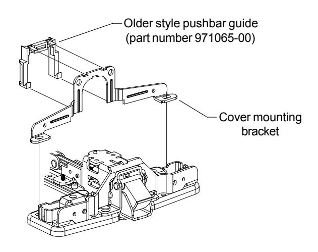
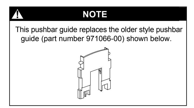
Also replaces older style pushbar guide (part number 971065-00). To replace, slide mechanism case away from center case. Remove cover mounting bracket from center case. Unhook older style pushbar guide from cover mounting bracket and discard. Replace cover mounting bracket. Install new pushbar guide.
Part Name: Pushbar Guide (rear) Kit Location: Middle drawer #12
Part Number: 090049-00 bulk, 10/pkg.
Use: 98/99 and 33/35 devices
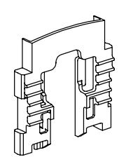
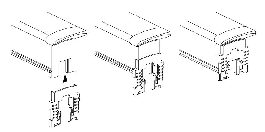
Installation: Remove pushbar from mechanism case. Slide guide onto back of pushbar.
Hold guide on pushbar and install pushbar on bellcranks. Slide base plate into
mechanism case.
4. Vertical Rod Parts
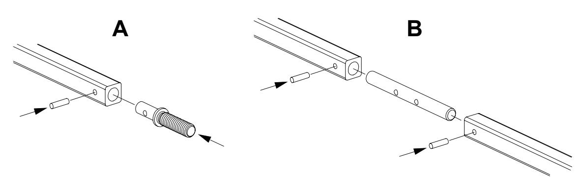
Part Name: Rod Extension Connector Kit Location: Top drawer #14
Part Number: 090075-00 bulk, 4/pkg.
Use: 98/9927 and 33/3527 devices on doors
taller than 7 feet
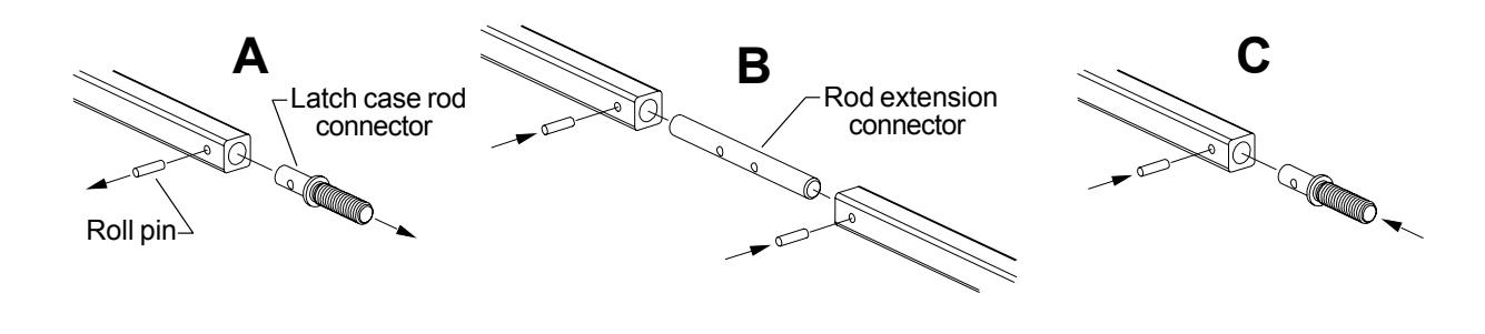
Installation: Drive out roll pin (963935-89) and remove latch case rod connector from latch
end of existing rod (A). Insert rod extension connector into latch end of existing rod and either end of extension rod and secure with roll pins (B). Insert latch case rod connector into latch end of extension rod and secure with roll pin (C).
Part Name: Extension Rod Drill Template-2227/98/9927 Kit Location:Top drawer #7
Part Number: 969298-89 unit
Use: To locate roll pin hole on 98/9927,
33/3527, and 2227 vertical rods
Installation: Slide template on rod until bottom of rod and bottom of template are flush. Drill
1/8" diameter hole through hole in template.
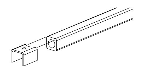
-Align bottom of template and bottom of rod before drilling
4. Vertical Rod Parts
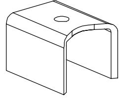
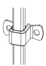
Part Name: 98/9927 Rod Guide Assembly Kit Location: Bottom drawer #14
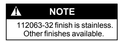
Part Number: 112063-32 unit
Use: 98/9927 and 2227 devices made after 1993
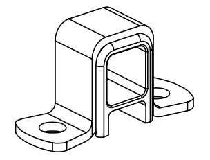
Installation: Slide over rod after rods have been adjusted. Place half way between device center case and latch. Secure to door with screws.
Part Name: 1/8 x 7/16 Roll Pin Kit Location: Top drawer #10
Part Number: 090054-00 bulk, 10/pkg.
Use: 98/9927 and 33/3527 vertical rods
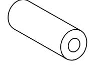
Installation: Line up holes in rod and latch case rod connector (A) or in rod and rod
extension connector (B) and drive roll pin through hole.
5. Surface Vertical Latch Parts
Part Name: 299 Strike Shim Kit Location: Top drawer #16
Part Number: 970321-89 unit
Use: 299 strikes to decrease spacing between
strike and latch
Installation: Position shim as shown. Prepare center hole per chart.
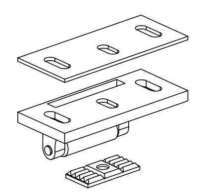
Metal Frame
Prep: #25drill and #10-24 tap Screw: 10-24 x 3/4 FPHMS
Wood Frame
Prep: 1/8" pilot drill x 1" deep Screw: 10 x 1 1/2 FPHWS
Part Name: Shim-264/299F/499F Strike Kit Location: Bottom drawer #15
Part Number: 945521-89 unit
Use: 264, 299F, and 499F strikes to decrease
spacing between strike and latch
Installation: Position shim with teeth facing strike and closest to strike roller. Mate teeth with
notches in bottom of strike. Prepare center hole per chart.
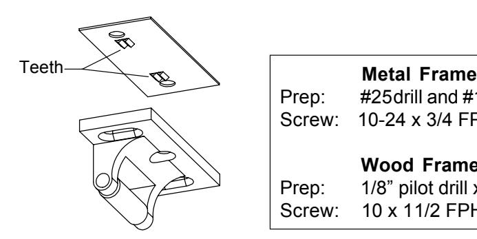
Prep: #25drill and #10-24 tap Screw: 10-24 x 3/4 FPHMS
Wood Frame
Prep: 1/8" pilot drill x 1" deep Screw: 10 x 1 1/2 FPHWS
5. Surface Vertical Latch Parts
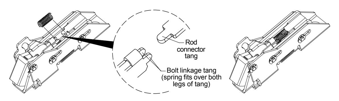
Part Name: Bolt Return Spring Kit Location: Bottom drawer #9
Part Number: 090065-00 bulk, 10/pkg.
Use: 98/9927/27-F and 2227/27-F top and bottom latches
98/9947/47-F and 33/3547/47-F bottom latches
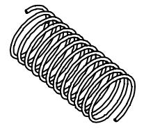
Installation: For 98/9947/47-F and 33/3547/47-F latch, remove Truarc retaining ring, latch
pin, and rod connecting screw for accessibility. Replace after installing spring.
98/9947/47-F and 33/3547/47-F Bottom Latch
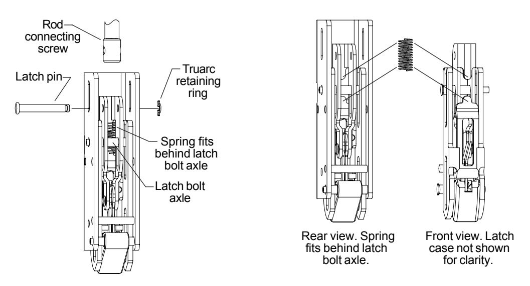
98/9927/27-F and 2227/27-F Top and Bottom Latches (98/9927/27-F Top Latch Shown)
5. Surface Vertical Latch Parts
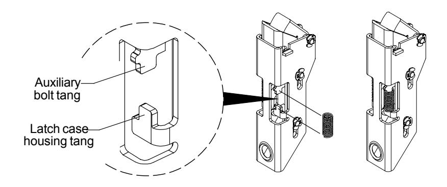
Part Name: 98/9927 Auxiliary Bolt Spring Kit Location: Top drawer #5
Part Number: 090076-00 bulk, 10/pkg.
Use: 98/9927 and 2227 top latches
Installation: Place one end of spring over over auxiliary bolt tang. Compress spring and
place free end of spring over latch case housing tang.
6. Concealed Vertical Latch Parts
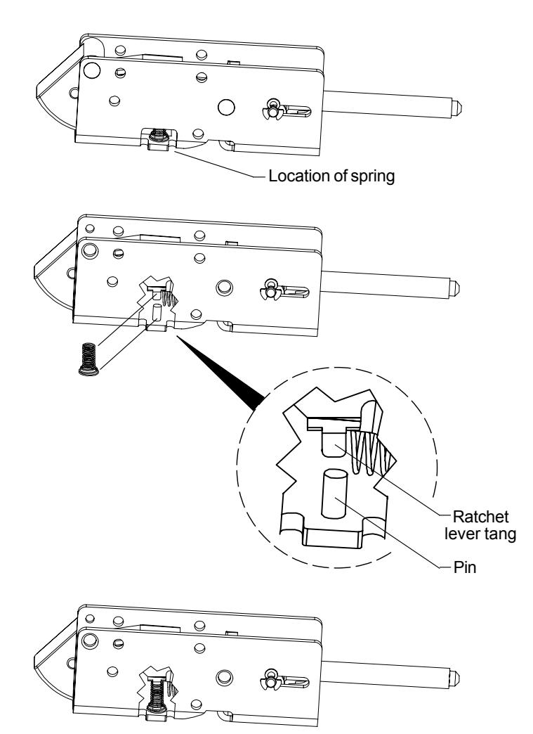
Part Name: Ratchet Lever Spring Kit Location: Middle drawer #7
Part Number: 090069-00 bulk, 2/pkg.
Use: 98/9947/47-F and 33/3547/47-F top latches
Installation: Place small end of spring over ratchet lever tang. Place large end of spring over
pin in latch case.
6. Concealed Vertical Latch Parts
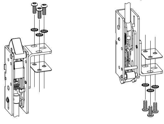
Part Name: #10 External Tooth Lock Washer Kit Location: Top drawer #3
Part Number: PKGSRV.1007 bulk, 10/pkg.
Use: To secure 98/9947 and 33/3547
latch mounting bracket
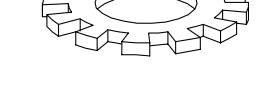
Installation: Use washer with screws that attach latch mounting bracket to door.
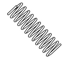
Part Name: Compression Spring-33/3547 Kit Location: Middle drawer #3
Part Number: 090066-00 bulk, 10/pkg.
Use: 98/9947 and 33/3547 top latch
Installation: Place small end of spring on latch bolt linkage tang, other end on latch case tang.
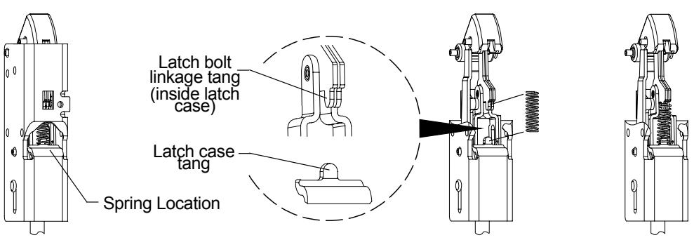
Latch case shown cut away for clarity
Part Name: 325 Sex Bolt Assembly Kit Location: Top drawer #4
Part Number: 034902-32 bulk, 2/pkg.
Use: For mounting 98/99, 33A/35A, and 22 latches
and latch mounting brackets made after Nov. 1998
Installation: Drill mounting holes per template supplied with device, 13/32" diameter
outside, 5/16" diameter inside. Hammer sex bolt through 13/32" diameter hole.
#325 sex bolt takes 1/4-20 thread screw.
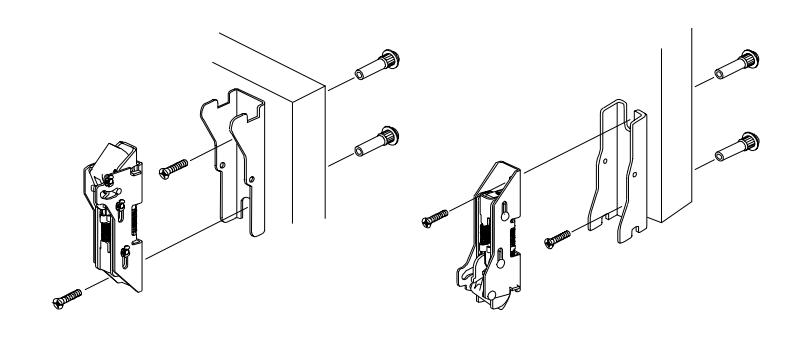
Part Name: 425 Sex Bolt Assembly Kit Location: Top drawer #49
Part Number: 034302-32 bulk, 2/pkg.
Use: For mounting 98/99 and 22 device surface
latches and latch mounting brackets made before Nov. 1998; for mounting 98/99, 33/35, and 22 device end cap brackets and center cases
(EO applications)
Installation: Drill mounting holes per template supplied with device, 13/32" diameter
outside, 1/4"diameter inside. Hammer sex bolt through 13/32" diameter hole.
#425 sex bolt takes 10-20 thread screw. (See diagram above)
Part Name: 10-12 x 10-24 x 1 PTHCS Kit Location: Top drawer #13
Part Number: 900919-00 bulk, 2/pkg.
Use: 98/9927 and 2227 device rod guide assembly
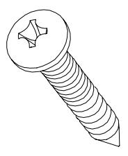
Installation: Use screws to mount 9927 rod guide assembly to door. For wood door, drill
1/8" diameter pilot holes. For metal door, use #25 drill and #10-24 tap.
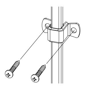
Part Name: 10-24 x 3/4 PPHMS Kit Location: Middle drawer #2
Part Number: PKGSRV.1015 bulk, 10/pkg.
Use: 98/99, 33/35, and 22 device mechanism
case mounting brackets
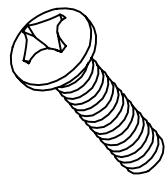
Installation: Use screws to mount 98/99, 33/35, and 22 device mechanism case mounting
brackets to door. For metal door surface mount, prepare door with #25 drill and
#10-24 tap. Screws also can be used with #425 sex bolts on 1 3/4" door.
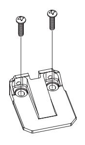
98/99 and 33/35 device mechanism case bracket
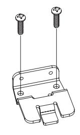
22 device mechanism case bracket
Part Name: 10-24 x 1 PPHMS Kit Location: Middle drawer #9
Part Number: PKGSRV.1016 bulk, 20/pkg.
Use: 98/99, 33/35, and 22 device center cases
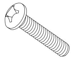
Installation: Use screws to mount 98/99, 33/35, and 22 device center cases to 1 3/4"
hollow metal doors. For surface mount, prepare door with #25 drill and #10-24 tap. Also can be used for through-mounting to trim and with #425 sex bolts.
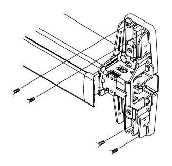
98/9927 center case shown
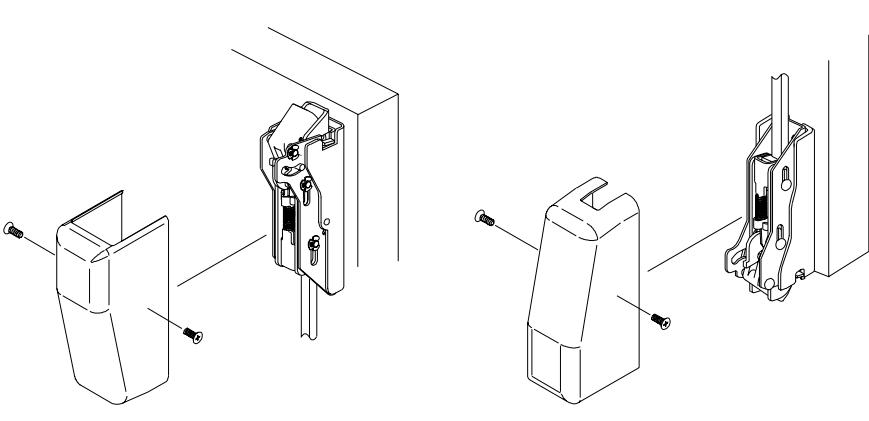
Part Name: 8-32 x 1/4 UFPHMS Kit Location: Top drawer #6
Part Number: PKGSRV.1018 bulk, 20/pkg.
Use: 98/9927 and 33/3527 latch case covers
Installation: Place latch case cover over latch case and secure with two screws.
Part Name: 10-24 x 3/4 UFPHMS Kit Location: Top drawer #1
Part Number: PKGSRV.1019 bulk, 10/pkg.
Use: 98/9927 and 2227 latches and latch mounting
brackets made before Nov. 1998
Installation: Use with #425 sex bolts. Drill mounting holes per template supplied with
device, 13/32" diameter outside, 1/4" diameter inside. Hammer sex bolt
through 13/32" diameter hole.
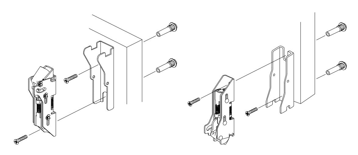
Part Name: 1/4-20 x 3/4 UFPHMS Kit Location: Bottom drawer #7
Part Number: PKGSRV.1020 bulk, 10/pkg.
Use: 98/9927 and 2227 latches and latch mounting
brackets made after Nov. 1998
Installation: Use with #425 sex bolts. Drill mounting holes per template supplied with
device, 13/32" diameter outside, 1/4" diameter inside. Hammer sex bolt
through 13/32" diameter hole. (See diagram above.)
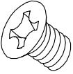
Part Name: 8-18 x 3/8 UFPHSMS Kit Location: Middle drawer #11
Part Number: 900892-32 bulk, 4/pkg.
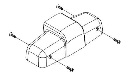
Use: 98/99 center case cover
Installation: Secure center case cover with four screws.
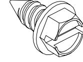
Part Name: 12-24 Mechanism Case Screw Kit Location: Bottom drawer #12
Part Number: 090073-00 bulk, 10/pkg.
Use: 98/99 and 33/35 devices; secures center case
cover mounting bracket to mechanism case
Installation: Remove two pine tree clips and replace with screws.
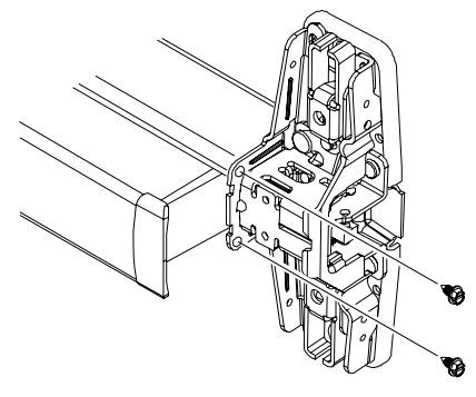
98/99 device shown
Part Name: Truarc Retaining Ring T5304-18 Kit Location: Top drawer #2
Part Number: 090107-00 bulk, 10/pkg.
Use: 98/99 and 22 rim latch bolt axle,
98/9927 and 98/9947 center case,
98/99, 33/35, and 22 main control link to control linkage
Installation: Use flat blade screwdriver to push ring over groove in pin so ring snaps in place.
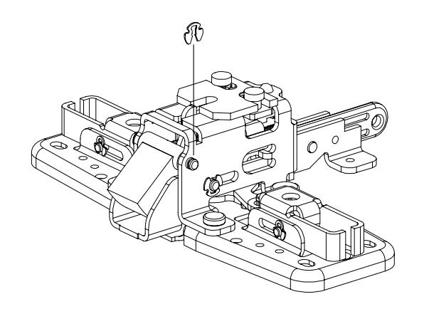
98/99 and 22 rim latch bolt axle (98/99 shown)
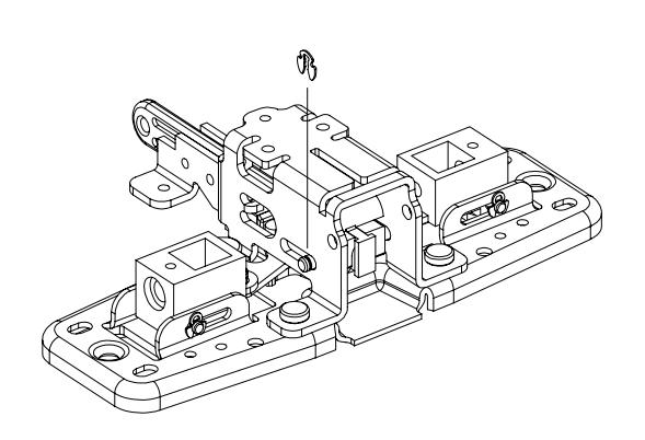
98/9927 and 98/9947 center case
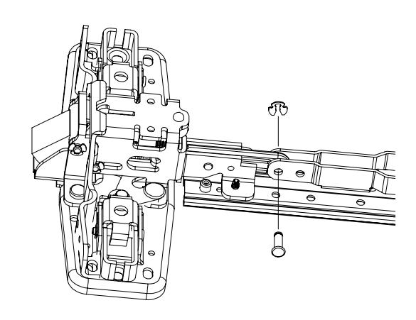
98/99 and 22 main control link to control linkage (98/99 shown)
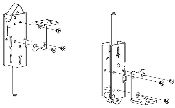
Part Name: 10-32 x 1/4 UFPHMS with Nylock Kit Location: Bottom drawer #1
Part Number: 090059-00 bulk, 6/pkg.
Use: 98/9947 and 33/3547 top and bottom
latch mounting brackets
Installation: Use screws to secure latch mounting brackets to latches.
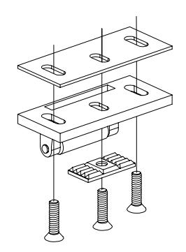
Part Name: 10-24 x 3/4 FPHMS Kit Location: Bottom drawer #8
Part Number: PKGSRV.1023 bulk, 10/pkg.
Use: 299 strike
Installation: Prepare mounting holes per template supplied with device using #25 drill and
#10-24 tap.

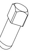
Part Name: Shear Pin Kit Location: Middle drawer #10
Part Number: PKGSRV.1010 bulk, 50/pkg.
Use: 991, 992, and 994 trim made after Jan. 1993
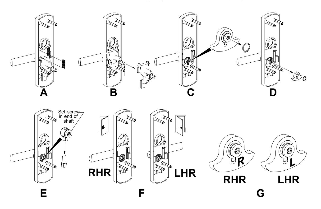
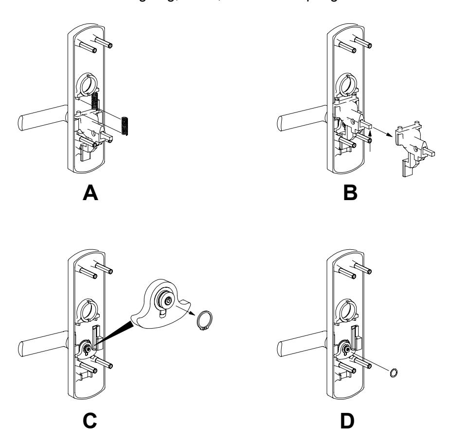
Installation: This procedure is for 992L R&V trim. For other trim, see trim instructions.
- 1. Remove trim from door.
- 2. Remove two lift springs (A).
- 3. Push slider up, then pull out (B).
- 4. Use retaining ring pliers to remove retaining ring (C).
- 5. Remove washer and cam (D).
- 6. Loosen set screw with 3/32" hex wrench and remove broken shear pin (E).
- 7. Place lever in desired position, RHR or LHR (F).
- 8. Insert new shear pin with head pointed down and tighten shear pin set screw.
- 9. Install cam. "R" faces out for RHR door, "L" faces out for LHR door (G).
- 10. Install washer, retaining ring, slider, and two lift springs.
Part Name: Cylinder Retaining Cup Kit Location: Top drawer #15
Part Number: 968201-89 unit
Use: 880, 990, 991, 992, and 994 trim with rim cylinders
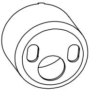
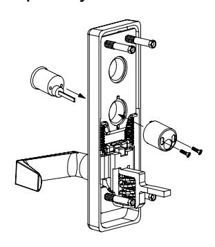
Installation: With trim off door, insert cylinder through trim. Install cylinder retaining cup
over trim so tabs on cylinder retaining cup align with notches on trim. Secure
cylinder retaining cup to cylinder with screws.
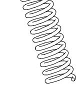
Part Name: 992/994 Lift Spring Kit Location: Bottom drawer #13
Part Number: 971573-00 unit; PKGSRV.1011 bulk, 20/pkg.
Use: 992/994 trim
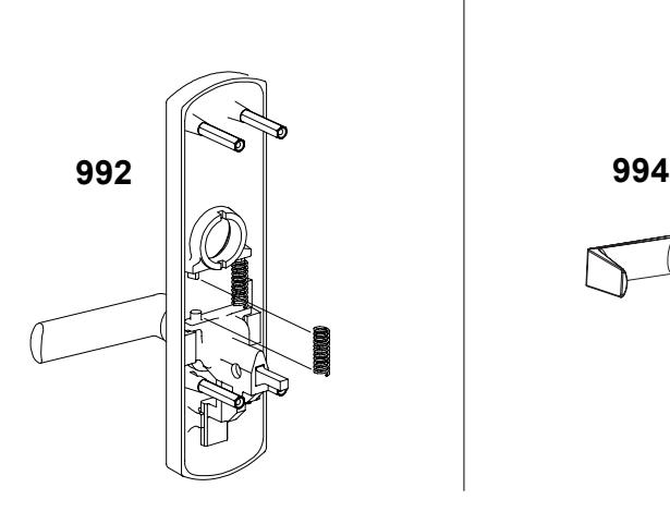
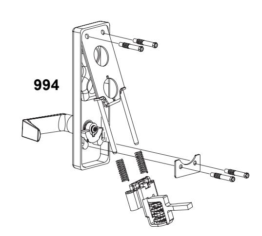
Installation: See pictures below for 992 and 994 spring installation.
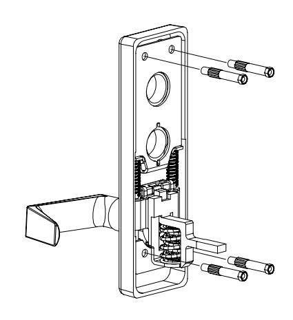
Part Name: Hex Stud-994/996 Trim Kit Location: Top drawer #4
Part Number: 971585-89 unit
Use: 994 and 996 trim
Installation: Screw stud into trim housing. Do not over-tighten.
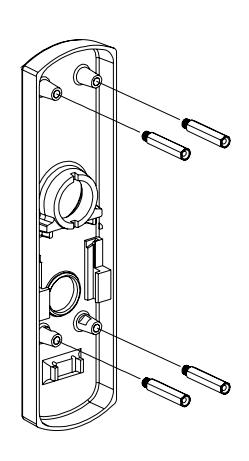
Part Name: 1/4-20 Hex Stud Kit Location: Middle drawer #5
Part Number: 971440-89 unit; PKGSRV.1012 bulk, 10/pkg.
Use: 991 and 992 trim made after March 1997
Installation: Screw stud into trim housing. Do not over-tighten.
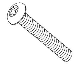
Part Name: 10-24 x 1 3/8 PPHMS Kit Location: Top drawer #12
Part Number: PKGSRV.1022 bulk, 10/pkg.
Use: To mount 991 and 992 trim on 1 3/4" doors
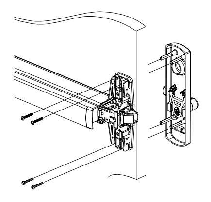
Installation: Bolt through device and door to hex studs on trim.
Part Name: Truarc Retaining Ring 5160-42 Kit Location: Middle drawer #6
Part Number: 964285-00 unit; PKGSRV.1013 bulk, 10/pkg.
Use: To secure cam on 991 and 992 trim
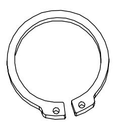
Installation: Use retaining ring pliers to open retaining ring. Slip ring over shaft and
position ring in groove in shaft.
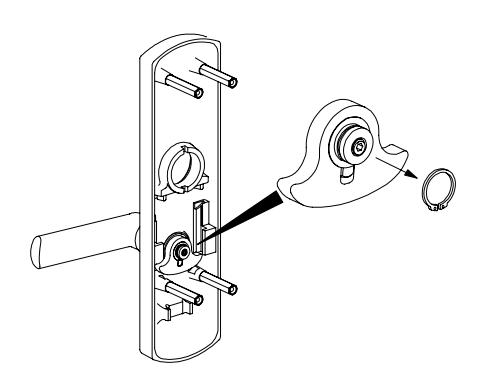
Part Name: Wave Spring Washer Kit Location: Middle drawer #1
Part Number: 090103-00 bulk, 10/pkg.
Use: Used on 992 and 370 series controls to eliminate
excessive lever movement perpendicular to the
face of the door
Installation: This procdure is for 992L R&V trim. For other trim, see trim instructions.
1. Remove trim from door.
- 2. Remove two lift springs (A).
- 3. Push slider up, then pull out (B).
- 4. Use retaining ring pliers to remove retaining ring (C).
- 5. Replace or install washer (D).
- 6. Install retaining ring, slider, and two lift springs.
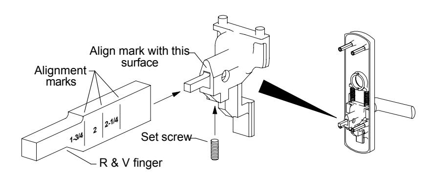
Part Name: 1/4-20 x 5/8 Socket Set Screw Kit Location: Bottom drawer #10
Part Number: 964353-76 unit
Use: 992 trim
Installation: Loosen or remove set screw. Slide the R&V finger in or out to align the mark for
the door thickness with the surface indicated. When aligned, tighten the set
screw with a 1/8" hex wrench.
Appendix A: Device Lubrication
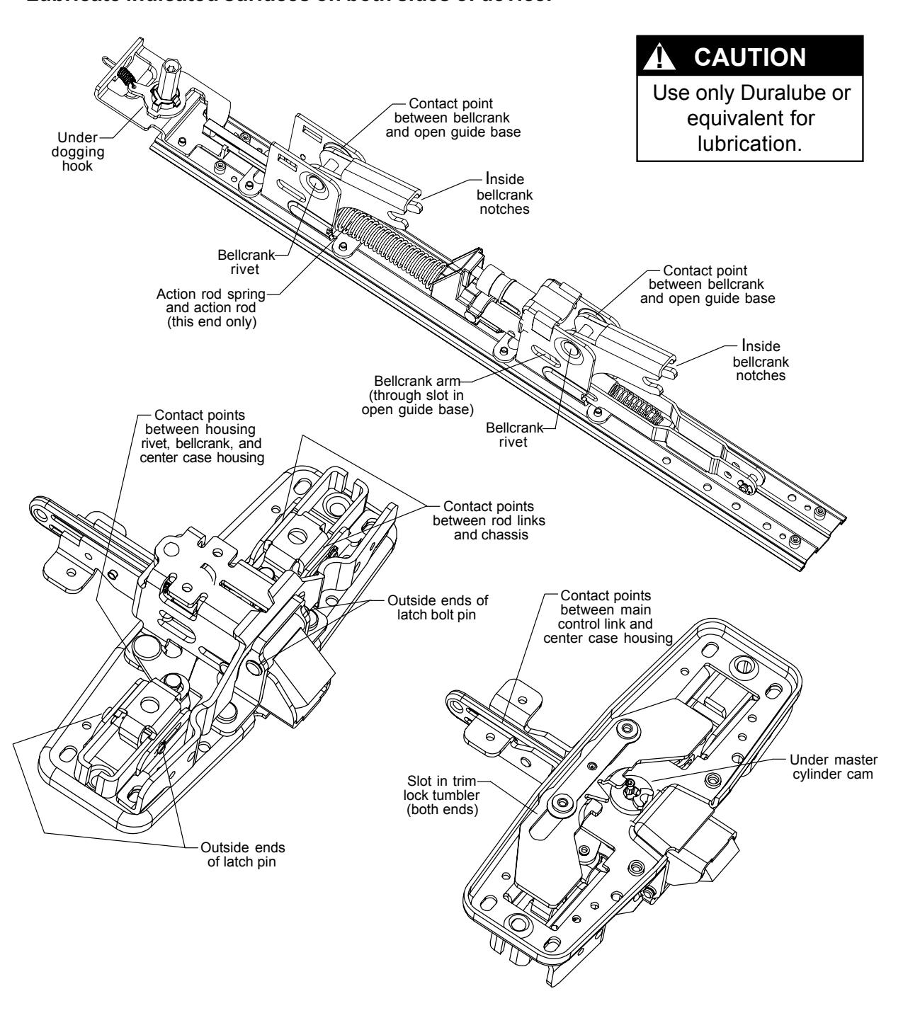
Devices are lubricated before delivery. Additional periodic lubrication will increase device life by inhibiting excessive wear of moving parts. Lubricate every four months with Duralube or equivalent . Recommended surfaces for lubrication are shown in the diagrams below. Lubricate indicated surfaces on both sides of device.
Appendix B: Latch Lubrication
Latches are lubricated before delivery. Additional periodic lubrication will increase latch life by inhibiting excessive wear of moving parts. Lubricate every four months with Duralube or equivalent . Recommended surfaces for lubrication are marked with ● in the diagrams below.
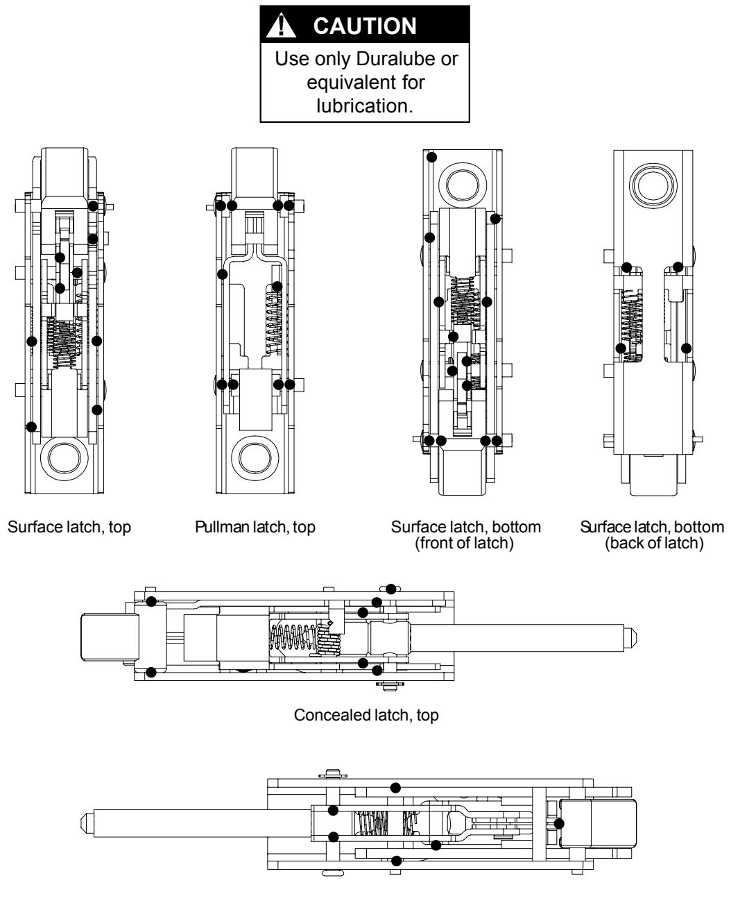
Concealed latch, bottom
Index by Part Number
| Part Number | Part Description | Page Number |
|---|---|---|
|
034302-32
(bulk) |
425
Sex Bolt Assembly |
7-1 |
|
034902-32
(bulk) |
325
Sex Bolt Assembly |
7-1 |
|
050156-00
(bulk) |
Tailpiece
Guide |
1-3 |
|
050491-00
(unit) |
Shock
Absorber and Holder Assembly |
3-3 |
|
050524-00
(unit) |
Mechanism
Case Mounting Bracke t |
3-1 |
|
090031-00
(bulk) |
Control
Link Pin-Touch Bar Device |
1-2 |
|
090036-00
(bulk) |
Anti-RattleSpring-33/35/98/99 | 3-2 |
|
090040-00
(bulk) |
Hex
Dogging |
Shaft2-1 |
|
090041-00
(bulk) |
Dogging
Spring2-3 |
|
|
090042-00
(bulk) |
Dogging
Adapter Spring |
2-2 |
|
090045-00
(bulk) |
Cylinder
Dog Actuator |
2-4 |
|
090046-00
(bulk) |
CD
Dogging Plug |
2-4 |
|
090049-00
(bulk) |
Pushbar
Guide (front) |
3-4 |
|
090049-00
(bulk) |
Pushbar
Guide (rear)3-5 |
|
|
090054-00
(bulk) |
1/8
x 7/16 Roll Pin |
4-2 |
|
090059-00
(bulk) |
10-32
x 1/4UFPHMS with Nylock |
7-7 |
|
090065-00
(bulk) |
Bolt
Return Spring |
5-2 |
|
090066-00
(bulk) |
Compression |
Spring-33/3547
6-2 |
|
090069-00
(bulk) |
Ratchet
LeverSpring |
6-1 |
|
090073-00
(bulk) |
12-24 Mechanism
Case Screw |
7-5 |
|
090074-00
(bulk) |
NL
DriveScrew-98/99 |
Device
1-2 |
|
090075-00
(bulk) |
Rod
Extension Connector |
4-1 |
|
090076-00
(bulk) |
98/9927
Auxiliary Bolt Spring |
5-3 |
|
090103-00
(bulk) |
Wave
Spring Washer |
8-5 |
|
090107-00
(bulk) |
Truarc
RetainingRing |
T5304-187-6 |
|
112063-32
(unit) |
98/9927
Rod Guide Assembly |
(stainless)
4-2 |
|
15-445-00
(unit) |
Hex
Dogging Replacement |
Kit
2-1 |
|
900892-00
(bulk) |
8-18
x 3/8UFPHSMS |
(chrome)7-5 |
|
900919-00
(bulk) |
10-12
x 10-24 x 1 |
PTHCS7-2 |
|
900597-00
(bulk) |
End
Cap Mounting |
Screw3-1 |
|
945521-89
(unit) |
Shim-264/299F/499F
Strike |
5-1 |
|
964285-00
(unit) |
Truarc
Retaining Ring |
5160-428-4 |
|
964353-76
(unit) |
1/4-20
x 5/8Socket Set |
Screw
8-6 |
|
968201-89
(unit) |
Cylinder
Retaining |
Cup
8-2 |
|
969298-89
(unit) |
Extension
Rod Drill |
Template-2227/98/99274-1 |
|
971585-89
(unit) |
Hex
Stud-994/996 |
Trim
8-3 |
|
970321-89
(unit) |
299
Strike Shim |
5-1 |
|
970441-89
(unit) |
NL
DriveScrew-98/99 |
Device
1-2 |
|
971440-89
(unit) |
1/4-20
Hex Stud |
8-3 |
Page: IPN-2
Index by Part Number (continued)
|
Part
Number |
Part
Description |
Page
Number |
|---|---|---|
|
971573-00
(unit) |
992L
Lift Spring |
8-2 |
|
PKGSRV.1007
(bulk) |
#10
External Tooth Lock Washer |
6-2 |
|
PKGSRV.1010
(bulk) |
Shear Pin
8-1 |
|
|
PKGSRV.1011
(bulk) |
992L
Lift Spring8-2 |
|
|
PKGSRV.1012
(bulk) |
1/4-20
Hex Stud 8-3 |
|
|
PKGSRV.1013
(bulk) |
Truarc
Retaining Ring 5160-428-4 |
|
|
PKGSRV.1015
(bulk) |
10-24
x 3/4 PPHMS 7-2 |
|
|
PKGSRV.1016
(bulk) |
10-24
x 1 PPHMS 7-3 |
|
|
PKGSRV.1018
(bulk) |
8-32 x 1/4 UFPHMS7-3 | |
|
PKGSRV.1019
(bulk) |
10-24
x 3/4 UFPHMS 7-4 |
|
|
PKGSRV.1020
(bulk) |
1/4-20
x 3/4 UFPHMS |
7-4 |
|
PKGSRV.1022
(bulk) |
10-24
x 1 3/8 PPHMS8-4 |
|
|
PKGSRV.1023
(bulk) |
10-24
x 3/4 FPHMS 7-7 |