Trine 4800F Electric Strike Installation Instructions
Open the original PDF document
View PDF4800F ELECTRIC STRIKE
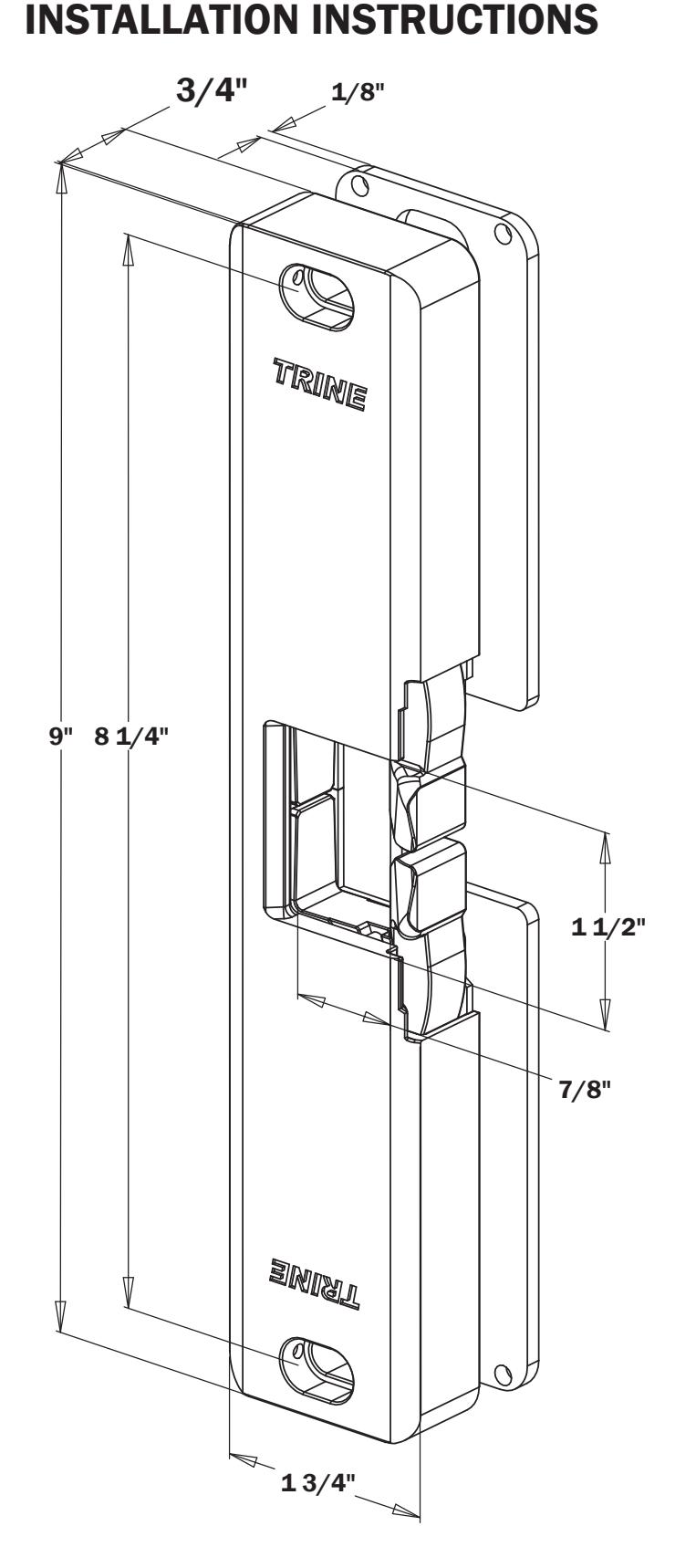

TRINE 4800F THE FIRE RATED SOLUTION FOR RIM PANIC EXIT DEVICES
Congratulations on the purchase of this quality TRINE security product. This product has been designed to install easily, perform reliably, and provide years of trouble free security.
BEFORE PROCEEDING with your installation, please review the following list of features. If you have any questions after reading this document please call TRINE's TECHNICAL SUPPORT (718) 829-2332, or visit us online @ trineonline.com
The 4800F is WH recognized for:
Class A, 3 Hour Single door / frame configuration of

- UBC 7-2, Uniform building Code
- CAN4 S104, Standard Method for Fire Tests of Door Assemblies NFPA 252
Issue: 1999/01/01 Standard Methods of Fire Tests of Door Assemblies
NOTE: WH fire listing is void when using fail safe action.
Intertek
BHMA Grade 1 Electric Strike
4800F ELECTRICAL CHARACTERISTICS:
| Pull-in/Hold | |||
|---|---|---|---|
| Voltage | Amps (A) | Duty | Sound |
| 12DC | .566 A/.217 A | Intm/Cont. | Silent |
| 24DC | .253 A/.099 A | Intm/Cont. | Silent |
| 12AC @ 50-60Hz | .509 A/.181 A | Intm/Cont. | Silent |
| 16AC @ 50-60Hz | .405 A/.149 A | Intm/Cont. | Silent |
| 24AC @ 50-60Hz | .215 A/.087 A | Intm/Cont. | Silent |
Built-in Electronics: The 4800F automaticallys allows 12-24AC & DC power, plus surge and kickback protection. There are no external 'pacs' to use or install.
OPERATING TEMP RANGE: -20°C TO +40°C DO NOT APPLY AN OVER VOLTAGE OF MORE THAN 10% OVER THE RATED OPERATING VOLTAGE OF THE STRIKE OR THE SOLENOID WILL BE DAMAGED.
WHAT IS INCLUDED IN THE 4800F BOX:
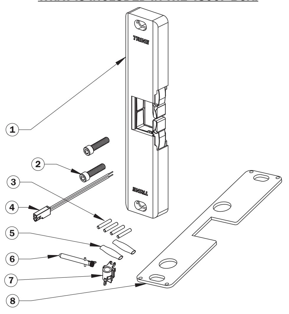
INCLUDED IN THE BOX ARE:
- 1 (1) 4800 OR 4801 SURFACE MOUNTED STRIKE
- 2 (2) 1/4-20 x 1" UH CAP SOCKET MOUNTING SCREWS
- 3 (4) ANCHOR SYSTEM PINS
- 4 (1) QUICK CONNECT SOCKET AND WIRE ASSEMBLY
- 5 (2) SEALED CRIMP CONNECTORS
- 6 (1) FAIL SAFE SPRING (RED COLORED) & SOLENOID PLUNGER
- 7 (1) FAIL SAFE CAM (NOTE: NOT FIRE RATED WHEN CONFIGURED FAIL-SAFE)
- 8 (1) 1/8" THICK SPACER PLATE/ FRAME MOUNTING TEMPLATE
RECOMMENDED PREINSTALLATION CHECK FOR THE 4800F SURFACE MOUNT STRIKE:
- 1. Determine that door is properly adjusted; Door must operate properly in order for system to provide best results.
- 2. Door must swing properly, without interfering with jamb or sill
- 3. The door should be equipped with a door closer and the door closer "latch mode" must hold door in a completely closed position in order to avoid the lock latch from applying pressure against the releasing latch portion of the electric strike.
- 4. Electrical wire connections must be completed and ready to be terminated inside the frame.
- 5. Confirm that the power line in the frame is the correct voltage, amperage, and that the switch works properly.
- 6. Confirm proper clearance exists between the end of the lock latch and jamb.
- 7. The electric door strike must be aligned properly with lock latch when it is installed on the doorjamb.
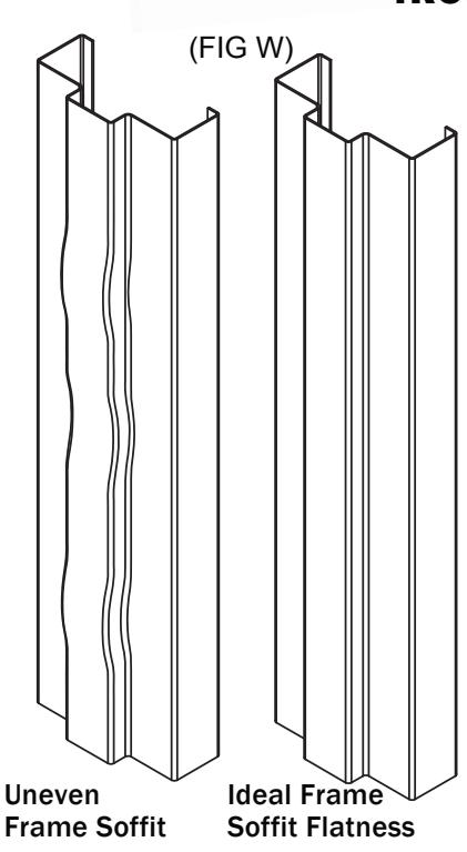
- 8. For best installation results, the door frame must be reasonably flat and straight. 2.
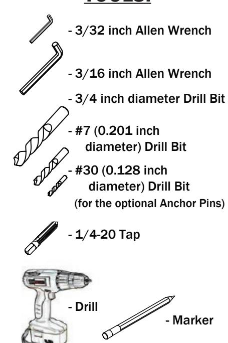
RECOMMENDED TOOLS:
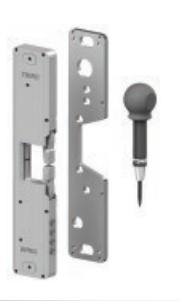
USE THE 4850ITL TO QUICKLY MARK, TEST, ADJUST, CENTER PUNCH AND SKIP MOST OF THESE STEPS! more info @ trineonline.com/4850itl.php
CHECK OUT THE VIDEO ON SEARCH "4850ITL"
INSTALLATION PROCEDURE:
CAUTION: TO AVOID ELECTRICAL SHOCK AND INJURIES, BEFORE DOING YOUR WIRING, TURN OFF THE POWER FROM THE CIRCUIT BREAKER.
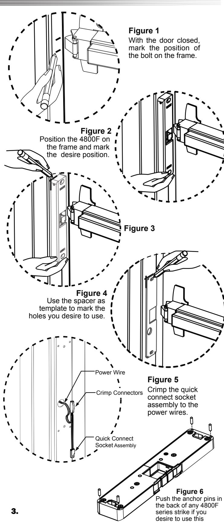
- 1. Mark the end position of the exit devices latchbolt on the doorframe. (Take off the original strike if present). See Figure 1.
- 2. Using the marks you just made as your guide, position the 4800F over the mark on the frame. Make sure that the Auxiliary latch rides up properly over the 4800's edge, and is engaged, and that the door is in the fully closed position. See Figure 2
- 3. When you are confident with the position of the 4800F, mark two perpendicular edges of the 4800F on the frame See Figure 3
- 4. Put the 4800F aside for a moment and place the spacer supplied with the 4800F inside the marks you just made on the frame.
- 5. Using the spacer as a template; mark the two mounting holes and the wire exit hole. If you are using the optional anchor pins, mark the anchor pin positions using the spacer as a template. See Figure 4
- 6. Using a #7 bit, drill the two mounting holes and tap them ¼-20.
- 7. Using a ¾ inch diameter bit, drill the power wire exit hole
- 8. If you are utilizing the anchor pin system, use a #30 bit, drill the four anchor pin holes.
- 9. Deburr any sharp edges around the holes after drilling, so that the 4800F will rest on a smooth clean surface and the wires will not be accidentally cut or damaged while installing.
- 10. Pull the power wiring down the door frame and through the ¾ inch diameter power wire hole.
- 11. Using the provided sealed crimp connectors, terminate the quick connect socket assembly to the power wires. See Figure 5 (NOTE: The 4800F is not polarized)
- 12. If you intend to use the anchor pins system, insert them into the four holes on the back side of the 4800F. See Figure 6. If you also intend to use the 1/8" thick spacer plate, you can now slip the plate over the pins.
- 13. Snap together the power supply side connector coming off the frame to the 4800 connector. Carefully push the wires and connectors back into the frame.
- 14. Using the 2 mounting screws, mount the 4800F strike to the frame.
- 15. Adjust the strike to the desired position and tighten the mounting screws using the 3/16 inch Allen wrench.
- 16. Using the 3/32 inch Allen wrench turn the two setscrews on the side of the 4800F until they support the strike. DO NOT over tighten the setscrews.
- 17. Turn the power ON and test your installation. Installation is now complete.
INSTRUCTIONS FOR CHANGING THE THE 4800F FROM FAIL SECURE TO FAIL SAFE:
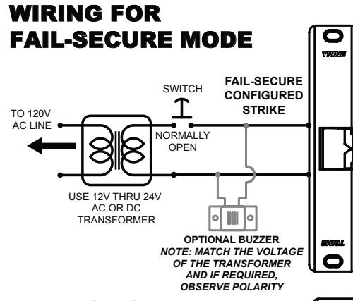
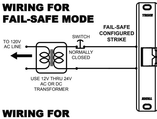
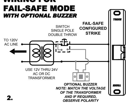
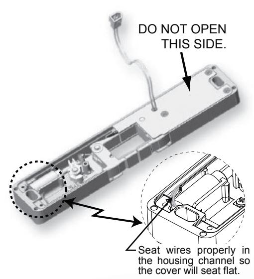
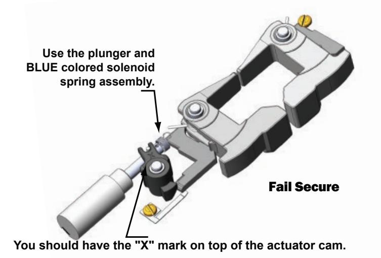
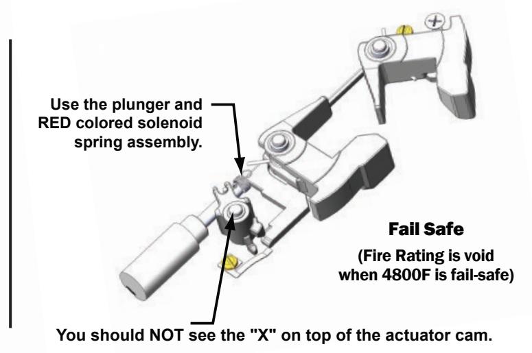
To change the Fail Secure 4800F into a Fail Safe, open the mechanism side of the strike (as shown on the right) by removing the mechanism cover screws (3 places) and the cover. Lift the solenoid and gently pull off the solenoid plunger and BLUE spring assembly and replace it with the solenoid plunger and RED colored spring assembly. Pull off the actuator cam, and replace it with the fail-safe cam. Before closing the unit, make sure that the wires are properly seated on the wire channel (see figure on right). Save the plunger and BLUE colored spring assembly for future use.
For changing from Fail Safe to Fail Secure, just reverse the above procedure
TROUBLESHOOTING THE COMPLETED INSTALLATION:
SYMPTOM: ELECTRIC RELEASE IS NOT ACTUATING:
1. Verify proper voltage is present AT STRIKE. If voltage is present: the strike may have been affected during the installation, or dirt or debris may be preventing proper operation. Inspect electric release and clean. NOTE: DO NOT LUBRICATE SOLENOID
2. If voltage IS NOT present:
A) Verify Circuit breaker is on, B) Verify voltage at the transformer/power supply output. C) Verify that there are no additional, external switches or devices which may be interrupting your circuit. D) Check for damaged wiring or bad wire splices.
SYMPTOM: STRIKE IS WORKING BUT WILL NOT OPEN:
- 1. Check for other locks on door
- 2. Check for proper lock-latch engagement
- 3. Check for excessive back pressure on door release latch by following these steps:
A) Push the door from the outside to try and relieve the bolt to latch pressure and actuate the 4800F. B) While the 4800F is unlatched swing the door open. If the door opens, then the bolt maybe applying pressure to the latch. Adjust the position of the 4800F to relieve the pressure.
POSSIBLE REMEDIES:
- 1. Re-adjust (or install) a door closer, Remove door silencers, Re-center electric release in jamb, Remove or trim weather stripping around the door.
- 2. Installing this strike on an uneven surface can cause problems with the internal mechanism of this device. Specifically, it will cause localized mechanical pinching of the moving parts. Locate where the pinching is occurring and level the frame surface at that location. (FIG W)