Trine 323478F-LC & 323478FX-LC ELlectric Strike Installation Instructions
Open the original PDF document
View PDF
SILENT OPERATION:
The 323478F-LC and FX operate silently; unlike some types of AC electric strikes that "buzz" when activated. For some applications, like entrances to apartment buildings, an audible sound is desirable. For other applications, such as offices, silent operation is preferred. Verify which they require. If louder signal, when the electric release activates, is needed, then use a 6DC Piezzo buzzer. Trine offers a BZ-6 for this purpose. The LC100 must always be used with the 30LC & 30RS units.
TROUBLESHOOTING THE COMPLETED INSTALLATION:
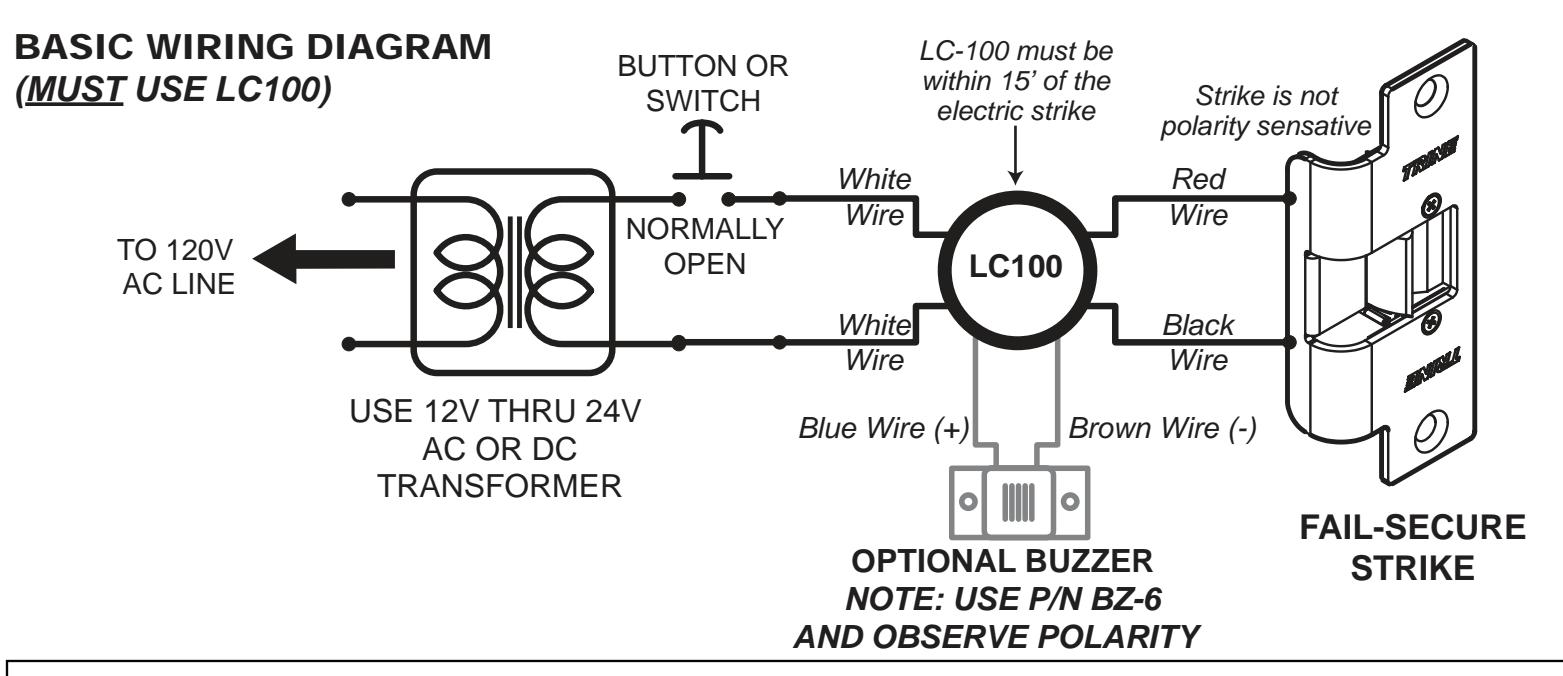
SYMPTOM: What is this Line Conditioner or LC100 for? 1. In the 323478F-LC kit, the LC100 is not optional, it must be installed between the power supply and strike mechanism, as seen on page 3. The LC100 'conditions' the power supply to allow the mechanism to run continuously (and so in Fail Safe configuration)
SYMPTOM: Electric release is not actuating:
- 1. Verify proper voltage is present AT STRIKE. If voltage IS present: the strike may have been damaged during the installation, or dirt or debris may be preventing proper operation. Inspect electric release and clean. DO NOT LUBRICATE SOLENOID.
- 2. Verify for proper electric release coil resistance (REFER TO COIL RESISTANCE CHART), for either a short circuit or open circuit. Coil is NOT a serviceable part.
- 3. If voltage IS NOT present:
- Verify Circuit breaker is on
- Verify voltage at the transformer/power supply output.
- Verify output from rectifier (if used)
- Verify that there are no additional, unknown external switches or devices which may be interrupting your circuit.
- Check for damaged wiring or bad wire splices.
- Check for other locks on door
- TION: "CONFIRMING PROPER LOCK-LATCH ENGAGE-MENT & CLEARANCES").
- latch by following these steps:
- While observing the electric release and latch; apply enough pressure on the door so that the lock latch does sure on the electric release latch. If electric release works properly while you are applying this pressure. then steps must taken to relieve this pressure.
Possible remedies include:
- Re-adjust (or install) a door closer
- · Remove door silencers
- Correct excessive door warpage
- Re-center electric release in jamb
323478F-LC & 323478FX-LC ELECTRIC STRIKES INSTALLATION INSTRUCTIONS
17/8"* 478 Faceplate w/ Mechanism *478X Faceplate is 2-1/4" wide
1 11/16"
(instead of
Fire Rated
Mechanism
(F)
1-7/8")

TRINE 323478F-LC & 323478FX-LC ELECTRIC STRIKES THE SMALLEST ELECTRIC STRIKE IN THE WORLD FOR CYLINDRICAL LOCKS AND DEADLATCHES
Congratulations on the purchase of this quality TRINE security product. This product has been designed to install easily, perform reliably, and provide years of trouble free security.
BEFORE PROCEEDING with your installation, please review the following list of features. If you have any questions after reading this document please call TRINE's TECHNICAL SUPPORT (203) 730-1756 ext. 447.
email: technicalservice@trineonline.com.
or visit us: www.trineonline.com
4 7/8"
4 1/8"
234 faceplate with
extended ramp
w/ mechanism
234 Faceplate
w/ Mechanism
The 323478F-LC & 323478FX-LC is WH recognized for:
Class A, 3 Hour Single door / frame configuration
- UL10C, Fire Tests of Door Assemblies
- UBC 7-2, Uniform Building Code
- CAN4 S104, Standard Method for Fire Tests of Door Assemblies NFPA 252

- BHMA Grade 1 Electric Strike
ELECTRIC STRIKE ELECTRICAL CHARACTERISTICS:
| Voltage |
Pull-in/Hold
Amps (A) |
Ohms (Ω) | Duty | Duty | |
|---|---|---|---|---|---|
| 12DC | 0.743/0.298 A | 13.0 | Intm/Cont | Silent | |
| 4" | 12AC | 0.715/0.277 A | 13.0 | Intm/Cont | Silent |
| 24DC | 0.397/0.170 A | 13.0 | Intm/Cont | Silent | |
| 24AC | 0.378/0.173 A | 13.0 | Intm/Cont | Silent |
The LC100 accepts 12-24AC & DC power, plus surge and kickback protection. Must be within 15' of the electric strike.
WARNING - PLEASE READ PRIOR TO INSTALL
- LC-100 (line conditioner) Must be used for ALL installations (LC100 outputs 9DC to fire the solenoid and drops to 5.5DC to hold the strike unlocked with power)
- Ensure pigtails for buzzer leads on LC100 are not touching. (If a buzzer is not being used)
- DO NOT Lubricate.
- DO NOT Apply an over voltage of more then 10% of the strikes operating voltage.
- NOT recommended for outdoor use
- Operating temperture range: -20°C through +40°C
SYMPTOM: Door will not open but strike is working:
- · Check for proper lock-latch engagement (SEE SEC-
- Lock latch engagement may not be set correctly. (If proper clearance cannot be achieved by installing a shim; a shorter lock latch may be required for your installation.)
- Check for excessive back pressure on door release
- not press on the electric release latch. If applying pressure from the latch, then there may be too much pres-
- Remove or trim weather stripping around the door
HONE: (203) 730-1756 FAX: (203) 730-1781 V. 17.1205
WHAT IS INCLUDED IN THE 323478F-LC & 323478FX-LC SERIES KITS:
- (1) 2-3/4" Adjustable Faceplate
- (2) 1/16" Strike Shims
- (1) 30F Mechanism
- (1) LC-100 (MUST use LC-100)
- (2) Mounting Screw
- (2) Tab Shims
- (2) 'Short' Strike Screws
- (2) 'Long' Strike Screws (for shims)
323478F-LC - comes with the 4-7/8" faceplate 323478FX-LC - comes with the extended ramp 4-7/8" faceplate
ELECTRIC STRIKE STANDARDS:
- Mortise Type 1" backset
- BHMA Grade 1 (Durability 500,000 Life Cycles, Holding Force 1,200 Pounds (Static Force)- 70 ft-lb (Dynamic Force))
- All stainless steel locking parts
- Solid Cast Latch Stainless Steel
- Cavity: Width 5/8", Height 1-1/8", Depth 1/2"
RECOMMENDED PRE-INSTALLATION CHECK LIST:
- 1. Determine that door is properly adjusted; Door must operate properly in order for system to provide best results.
- 2. Door must swing properly, without interfering with jamb or sill
- 3. The door should be equipped with a door closer and the door closer "latch mode" must hold door in a completely closed position in order to avoid the lock latch from applying pressure against the releasing latch portion of the electric strike.
- 4. Electrical wire connections must be completed and ready to be terminated inside the frame.
- 5. Confirm that the power line in the frame is the correct voltage, amperage, and that the switch works properly.
- 6. Confirm proper clearance exists between the end of the lock latch and jamb.
- 7. The electric door strike must be aligned properly with lock latch when it is installed on the doorjamb.
- 8. For best installation results, the door frame must be reasonably flat and straight.
INSTALLATION PROCEDURE:
CAUTION: TO AVOID ELECTRICAL SHOCK AND INJURIES, BEFORE DOING YOUR WIRING, TURN OFF THE POWER FROM THE CIRCUIT BREAKER.
- 1. Verify strike is proper for the door into which it is to be installed.
- 2. Verify that you have all parts required to complete the installation.
- 3. Verify that the new electric release operates with the existing power supply/control circuit (retrofit applications); or verify that the new power supply/ control circuit operates the new electric release (new installations).
- 4. Locate and clearly mark the circuit breaker which provides AC power to your transformer/ power supply or that supplies power to the receptacle into which you will plug your transformer/power supply. This will enable you to safely cut power during installation, and permit troubleshooting if required.
- 5. Verify that a wall switch, time clock or other external device does not control the receptacle or circuit providing power to the electric release.
- 6. Verify that the circuit/receptacle used for the locking system is not powering any other equipment. Remember that interruption of power to your locking system could prevent access into the protected area, or jeopardize the security & safety of the site's occupants.
- 7. Verify that the door and associated components are in good working order. These items are essential for either new installations or retrofit items which should be specifically checked prior to beginning the installation include:
- The hinges (or pivots) are in good condition
- If your installation is a retrofit, that the existing latch lines up perfectly with the existing strike plate.
- The door is not rubbing on the saddle or anywhere on the frame
- The door closer is not leaking and is in good condition and properly adjusted.
- The door is not warped or otherwise damaged which might hamper its operation or otherwise affect your installation or the final system's performance.
- That the door frame member into which the door release is to be installed is deep enough (1 inch) for the body of the electric strike, and that the wiring to operate the electric release can be installed.
- 8. Install electric release as per attached guidelines.
- 9. Wire electric release as per attached guidelines.
- 10. Perform final test of completed installation.
INSTALLATION OF SHIMS:
An adequate amount of clearance must exist between the door latch and the strike keeper so that they do not interfere or bind when the door opens or closes.
• Two (2) 1/16" thick "C" shaped shims are supplied with this unit which may be installed as shown in the "Installation Drawing section" to resolve this situation if this problem is encountered. (also See Figure 4 below)
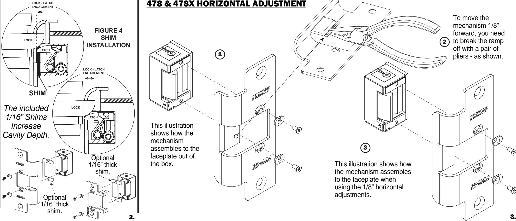
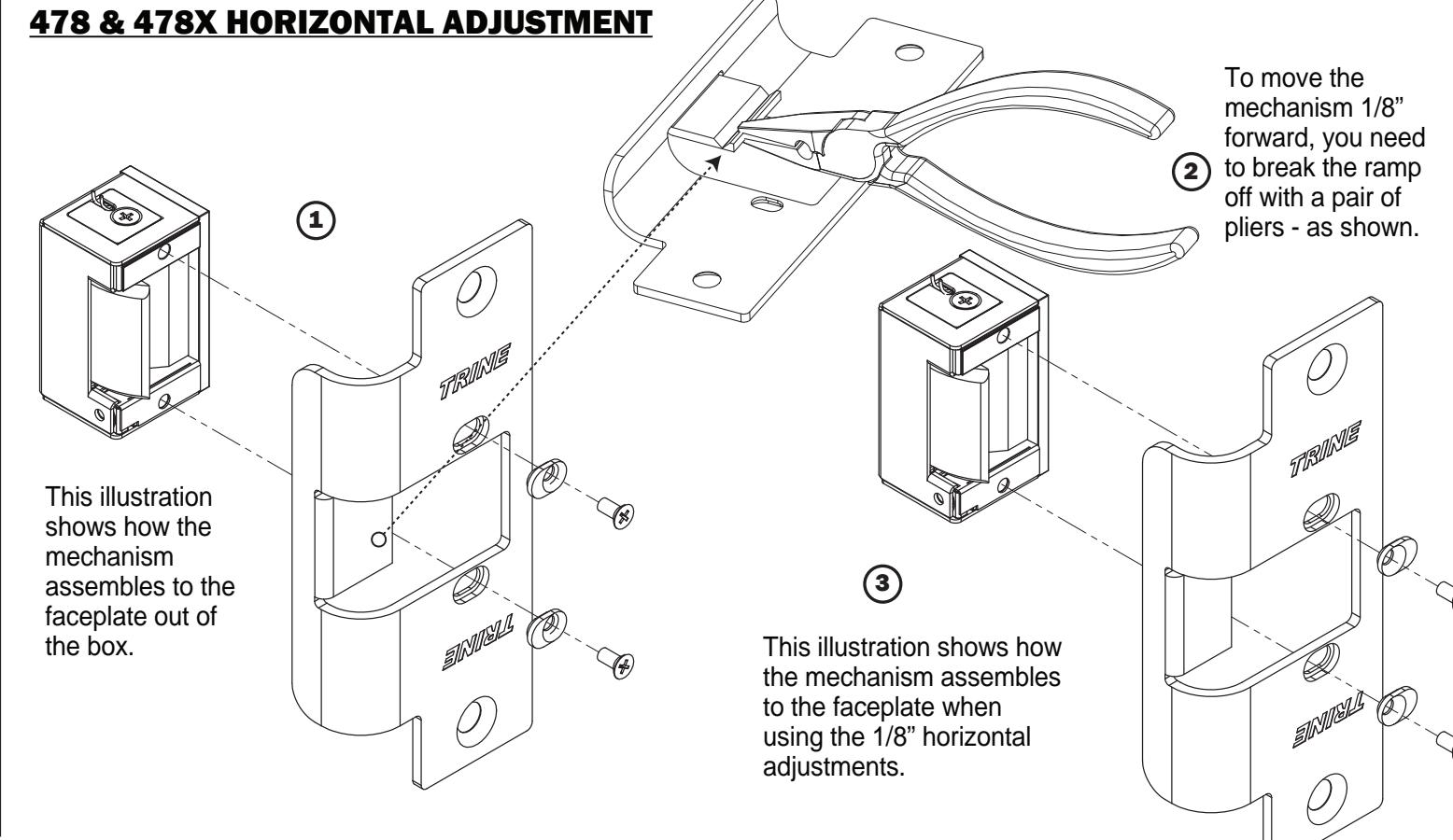
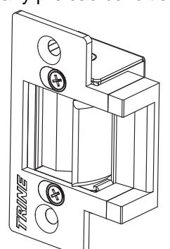
The 323478F-LC kit's 234 Faceplate is horizontally adjustable. In this illustration, the mechanism is mounted on a normal position.
The illustration below shows the mechanism moved forward for the purpose of relieving any preload condition.
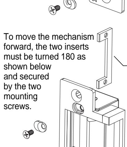
Remove the gap
insert.
These two insert and mounting screws hold the mechanism in place.
Mounting Screws
Adjustment Inserts
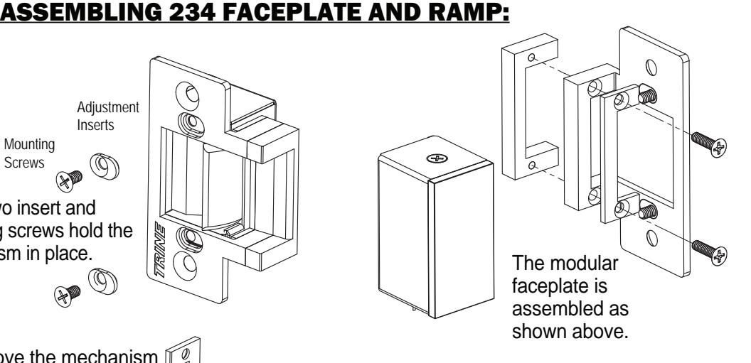
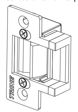
The modular faceplate when the mechanism is positioned forward is assembled as shown above. Do not use the insert.