Surewave CM-331 and CM-332 Manual
Open the original PDF document
View PDF

CM-331 & CM-332 Series Active Infrared "Hands-Free" Switches
INSTALLATION INSTRUCTIONS

SECTION 1: GENERAL DESCRIPTION
Sure-Wave™ hands-free switches are active infrared devices designed for use with an automatic door operator or other access control products.
Applications include low-energy doors, drive-up windows, health-care facilities, manufacturing… etc.
These units will fit in a variety of locations from 1 ¾" door frames to single and double gang electrical boxes. Various sized surface mount boxes are available from Camden.
There are 2 Line Powered models available:
CM-331 – Single relay output
CM-332 – Dual relay output
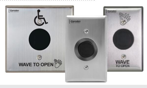
Three standard faceplates widths are available:
Jamb Mount /N : 1 ¾" x 4 ½" polycarbonate or stainless steel, fits 1 ¾" door frames or our CM-23D jamb box.
Single Gang : 2 ¾" x 4 ½" polycarbonate or stainless steel, fits on single gang electrical boxes
Double Gang /W : 4 ½" x 4 ½" polycarbonate or stainless steel, fits on double gang or 4 x 4 electrical boxes.
All faceplates are available with a variety of graphics/text:
/40 Waving Hand symbol
/41 Waving Hand Icon and Wave to open text
/42 Waving Hand Icon, Wave to Open text and Wheelchair symbol
Light Ring – SGLR Option
Camden CM-331 and CM-332 Sure-Wave are available with a light ring option. This provides an illuminated ring for visual confirmation of the switch activation. The light ring can be set to various combinations of colors, Blue, Blue-Red, or Green-Red.
CM-TX-99 RF Module
Camden CM-331 and CM-332 Sure-Wave can be fitted with an optional Lazerpoint CM-TX-99 RF Module. The CM-TX-99 RF Module enables the Sure-Wave to product an RF output when activated, that is compatible with our Lazerpoint Series receivers.
SECTION 2: INSTALLATION
Mounting
Sure-Wave may be mounted in door jambs, single or double gang electrical boxes, and 4 x 4 boxes.
NOTE: The sealing gasket (included) is recommended for outdoor or wet locations. If using with Automatic doors install in accordance with ANSI A156.10 / A156.19. Select from one of the following three mounting subsections:
Single Gang Electrical Box: CM-331 & CM-332
- 1a If using an in-wall box ensure the box is plumb and square, and flush with the wall surface. (See Diagram 1)
- 1b If using a surface box, ensure it is secure & plumb.
- 2 Bring your 4-conductor wire through the back or side of the enclosure and leave approximately 6" tail for wiring connection.
- 3 Make the electrical connections to the device according to the wiring section (following).
- 4 Using the dip switch located on the end of the unit, set the operating mode. (See Section 4)
- 5 Attach the unit to the enclosure using the two #6-32 screws provided.
- 6 Apply power and adjust range and time delay via the potentiometers on the front of the unit. (See Section 4 for adjustments)
- 7 Attach the faceplate to the unit using the two black #6-32 x 3/8 machine screws or tamperproof screws.
Do not overtighten!!
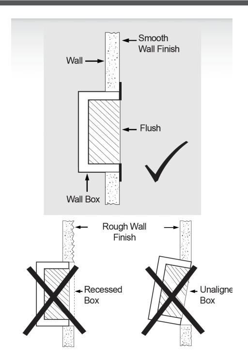
Diagram 1 - Proper Box Installation
- 2-Gang (or 4x4) Electrical Box: CM-331W & CM-332W
- 1a If using an in-wall box ensure the box is plumb and square, and flush with the wall surface. (See Diagram 1)
- 1b If using a surface box, ensure it is secure & plumb.
- 1c If using a 4 x 4 box, ensure the box is plumb and square, and flush with the wall surface, then attach the metal adaptor plate (included in the CM-331W & CM-332W packages) to the box using appropriate fasteners.
- 2 Bring your 4-conductor wire through the back or side of the enclosure and leave approximately 6" tail for wiring connection.
- 3 Make the electrical connections to the device according to the wiring section (following).
- 4 Using the dip switch located on the end of the unit, set the operating mode. (See Section 4)
- 5 Attach the unit to the enclosure using the two #6-32 screws provided.
- 6 Apply power and adjust range and time delay via the potentiometers on the front of the unit. (See Section 4 for adjustments)
- 7 Attach the faceplate to the unit using the two black #6-32 x 3/8 machine screws or tamperproof screws.
Do not overtighten!!
Door Frame: CM-331W & CM-332W
1a – If mounting directly in a 1¾" wide aluminum jamb, make a cutout in the door frame at the intended location as per Diagram 2 on page 4.
Drill and tap two mounting holes as shown.
- 1b If mounting the unit in our CM-23d deep jamb box, first mount the jamb box according to the instructions packaged with the enclosure. Using the CM-23D as a guide, drill a wire access hole through the jamb to fish the wiring through.
- 2 Bring your 4-conductor wire through the back or side of the enclosure (or Jamb) and leave approximately 6" tail for wiring connection.
- 3 Make the electrical connections to the device according to the wiring section (following).
- 4 Using the dip switch located on the end of the unit, set the operating mode. (See Section 4)
- 5 Attach the unit to the enclosure or jamb using the two #6-32 screws provided.
- 6 Apply power, and adjust range and time delay via the potentiometers on the front of the unit. (See Section 4 for adjustments)
- 7 Attach the faceplate to the unit using the two black #6-32 x 3/8 machine screws or tamperproof screws.
Do not overtighten!!
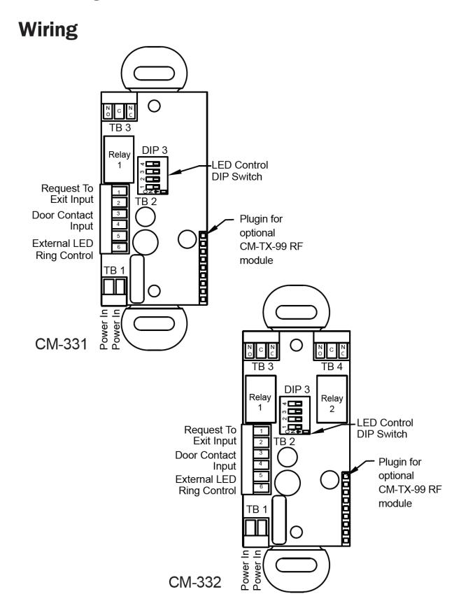
Caution : Do not apply power to the unit until all secondary wiring is complete, and dip switches have been set.
Power - TB1
Camden CM-331/332 Sure-Wave switches can be powered from 12 or 24 Volts, AC or DC. Connect power to pins 1&2 on the TB1. This is a non-polarized connection.
Inputs
Camden Sure-Wave switches provide inputs for Door Contacts, Request to Exit and remote control of the LED Light ring. These inputs are found on TB2. All inputs require a dry contact closure to operate.
TB2 Inputs
|
Pin
Number |
Function | Description | |||
|---|---|---|---|---|---|
| 1 | Request to Exit | A dry contact closure across these inputs | |||
| 2 | Request to Exit | will activate the relay(s) as per their settings. | |||
| 3 | Door Contact | Name ally closed the offer Counity Made | |||
| 4 | Door Contact | Normally closed, Used for Security Mode | |||
| 5 | Remote LED | External light ring control. A closed dry | |||
| 6 | Remote LED | contact on this input will toggle the light ring color. | |||
Outputs
The Sure-Wave switches provide Form 'C' relay outputs. The CM-331 has 1 Form 'C' output and the CM-332 has 2 Form 'C' outputs. Selecting the correct output is also dependant on the operating mode chosen. Most applications will utilize the N.O. and Common terminals.
Relay 1 Output (TB3)
| 1 | Normally Closed |
|---|---|
| 2 | Common |
| 3 | Normally Open |
Relay 2 Output (TB4), (CM-332)
| 1 | Normally Closed |
|---|---|
| 2 | Common |
| 3 | Normally Open |
SECTION 3: APPLICATIONS & SET-UP APPLICATIONS
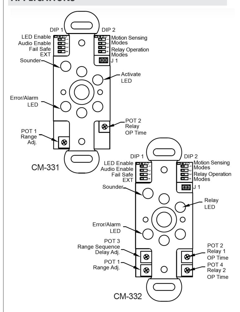
DIP 1 - Options Switch
SW1 - LED Enable
When SW1 is ON, the green LED will illuminate when the switch is activated. When SW 1 is OFF (default), the green LED will remain off.
SW2 - Audio Enable
When SW2 is ON, an audible beep is generated when the switch is activated. When SW2 is OFF (default), no audible beep is generated.
SW3 - Fail Secure/Fail Safe
This option changes the state of the relays on the Sure-Wave switches. When SW3 is ON, the relay outputs are switched. NO becomes NC and NC becomes NO. SW3 is OFF by default.
SW4 - External LED Control
The LED light ring can be controlled externally by providing a contact closure on the REM input (pins 5&6) on TB2. When SW4 is ON, a contact closure across the REM input will change the light ring color from its idle to active colors. When SW4 is OFF, the light ring colors change with the state of the switch.
CM-331 & CM-332 SERIES ACTIVE INFRARED "HANDS-FREE" SWITCHES
INSTALLATION INSTRUCTIONS
| DIP3 - | Light | Ring | DIP | Switch |
|---|
| SW1 | SW2 | SW3 | IDLE | ACTIVE |
|---|---|---|---|---|
| OFF | OFF | OFF | No Color | No Color |
| OFF | OFF | ON | Green | Blue |
| OFF | ON | OFF | Blue | Green |
| OFF | ON | ON | Green | Red |
| ON | OFF | OFF | All OFF | Blue |
| ON | OFF | ON | Red | Blue |
| ON | ON | OFF | Red | Green |
| ON | ON | ON | Blue | Red |
DIP 1 SW4 - External Light Ring Control
ON = Enabled, OFF - Disabled
When SW4 is ON, the light ring changes color according to the above table but will follow the state of the External Input on TB5.
Open = Active Closed = idle
When SW4 is OFF, the light ring changes color according to the above table but follows the status of relay 1.
DIP2 - Mode Switch
Camden line powered Sure-Wave provide Relay Operating Modes and Motion Sensing Modes. These modes work together to provide up to 16 Operating Scenarios.
DIP 2 switches 3&4 control the Relay operating modes. There are 4 Relay operating Modes available described in the table below.
Relay Operating Mode
| Mode | Mode Operation | ||||||
|---|---|---|---|---|---|---|---|
|
Operational
Mode Name |
SW3 | SW4 | |||||
| Simple mode | OFF | OFF | Only relay 1 operates | ||||
| Sequenced mode | ON | OFF | Relay 1 operates, delay, relay 2 operates sequenced fashion | ||||
| Security mode | OFF | ON |
Relay 2 operates first, delay,
and then relay 1 operates. Relay 2 releases after door contact closes (security mode). Alarm generated if door sensed open for 30 seconds |
||||
| Toggle mode | ON | ON |
Toggle mode – relay 1 toggles,
relay 2, if installed, operates when relay 1 is toggled on |
||||
NOTE: Modes referring to Relay 2 are valid for the CM-332 only.
Simple Mode
When an object is in range of the sensor, only Relay 1 will operate. Relay 1 will operate for the amount of time set by POT 2.
Sequenced Mode (CM-332 Only)
When an object is in range of the sensor, Relay 1 is activated, then Relay 2 is activated. Relay 1 will activated for the amount of time set by POT 2. Relay 2 will activate for the amount of time set by POT 4. The delay between Relay 1 and Relay 2 activation is set by POT 3.
Security Mode (CM-332 Only)
When an object is in range of the sensor, Relay 2 activates first. After the delay set by POT 3, Relay 1 activates. Once the door is closed, Relay 2 is released. If the door is held open for more than 30 seconds, an alarm is generated.
Door Contact Input and Security Mode
The door contact input is used to sense the magnetic door contact. The door contact closure is sensed prior to sequencing. Relay 2 will remain operated until the door contact closure is sensed. If the door contact was sensed to be closed prior to sequencing and does not close within 30 seconds of relay one release, the audio and visual alarms are set and only cleared when the door contact closes.
Toggle Mode
When an object is in range of the sensor, Relay 1 will activate. Relay 1 remains activated until an object is in range of the sensor again. Relay 2 will follow Relay 1 as if in Sequenced Mode. After the delay set by POT 3, Relay will activate for the amount of time set by POT 4. Relay 2 does not activate again on the 2nd activation of Relay 1.
Motion Sensing Modes
DIP 2 switches 1&2 control the Motion Sensing Modes. There are 4 Motion Sensing modes available described in the table below.
| Mode Name | SW1 | SW2 | |
|---|---|---|---|
| Momentary | OFF | OFF | Operates momentarily, will not re-engage unless object is removed first and then put back. No audio or visual alarm triggered. |
|
Momentary
with Alarm |
ON | OFF | Operates momentarily, will not reengage unless object is removed first and then put back. Alarm (audio and visual) generated if object remains in front of unit for 30 seconds. |
|
Operate
and stay operated – no alarm |
OFF | ON | Unit will continue to operate, relays stay engaged. No audio or visual alarm triggered. |
|
Auto Range
Mode |
ON | ON | Stuck on condition is approx 10 inches. Normal operation in this mode is the same as SO Mode 0/1 (dependant on number of relays). Unit will sense environment and automatically shrink the envelope in response to environment. Use this mode to sense across a hallway with range set to maximum. |
There are 4 Motion Sensing modes available described in the table below.
Momentary
When an object is in range of the sensor, Sure-Wave operates momentarily. It will not operate again until the object is removed and presented again. If the object remains in range of the sensor, no alarms are generated.
Momentary with Alarm
When an object is in range of the sensor, Sure-Wave operates momentarily. It will not operate again until the object is removed and presented again. If the object remains in range of the sensor for more than 30 seconds, an audible and visual alarm is generated.
Maintained
When an object is in range of the sensor, Sure-Wave activates and stays activated for as long as the object is in range of the sensor. Once the object is removed, the Sure-Wave deactivates.
Auto Range
The Auto Range Mode continually senses the environment and adjusts Sure-Wave accordingly to eliminate false triggers. Sure-Wave will calibrate itself with the first stationary object detected. Objects in motion behind the stationary object are not detected, but objects in motion in front of the stationary object are detected by Sure-Wave. If another stationary object is place in front of the original stationary object, Sure-Wave re-calibrates itself against the new stationary object. Objects in motion between the old stationary object and the new stationary object are not detected while objects in motion between Sure-Wave and the new stationary object are detected.
Adjusting the Range
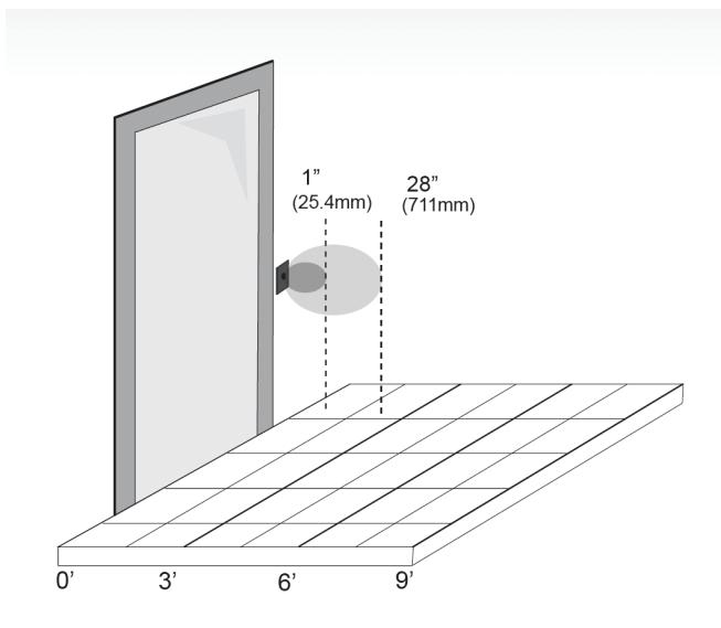
The range on this unit has been set to approx. 12" at the factory. If the desired range is less than 12", turn the range adjustment (POT 1) counterclockwise until the range is set. Use a piece of paper or your hand to test the range. If the desired range is greater than 12", but less than 24", turn the range adjustment (POT 1) clockwise until the range is set. Use a piece of paper or your hand to test the range.
SECTION 4: SYSTEM INSPECTION INSTRUCTIONS
After the Installation and operational check of the system:
- 1. Place warning label on the door (as per ANSI A156.10 or A156.19 guidelines). This will advise the person entering the swing side zone that the door will move.
- 2. Instruct the owner on door system operation and how to test it. This should be checked on a daily basis.
- 3. Instruct the owner on what to do if the door or any of its components become damaged.
- 4. Strongly recommend to the owner that the complete entry be inspected twice a year as part of the service agreement.
SECTION 5: TECHNICAL DATA
| No. of IR Sensors | (2) | ||||
|---|---|---|---|---|---|
| Operating Voltage | 12-24 Volts, AC/DC ± 10% | ||||
| Current Draw | 40 mA | ||||
|
Standard Operating
Range |
1"- 28" (25.4mm - 711.2mm)
Factory Set to 12" (304mm) |
||||
|
Auto Range
Operation |
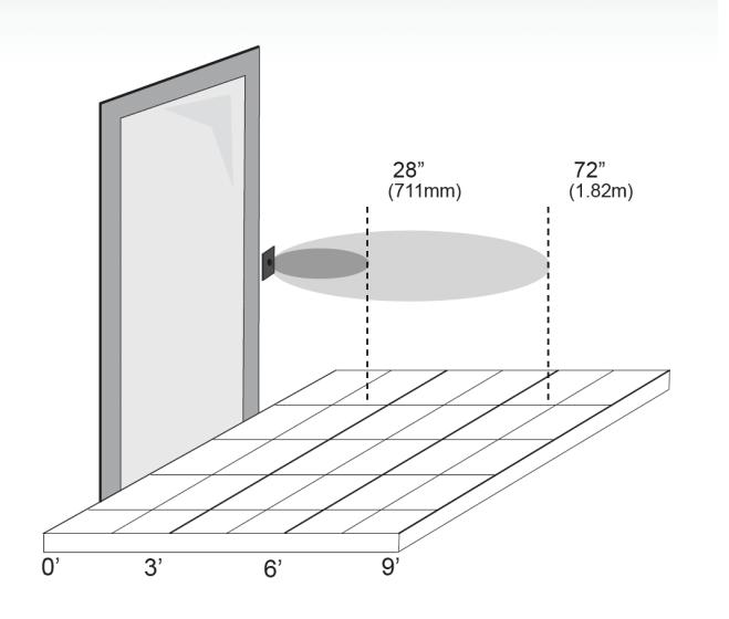
6"-40" (152.4mm – 1.016m) Hand
6"-72" (152.4mm – 1.820m) Body |
||||
| Relay Contact | 3 Amps @ 30 V DC | ||||
|
Relay Operating
Time |
3 - 30 Seconds | ||||
| Active Output | 9-12V | ||||
| Output Type | Fail Secure or Fail-Safe | ||||
| Inputs |
- 'Request To Exit'
- External (Door Contact) Input |
||||
| Optional LED Ring | On/Off, Red, Blue, Green | ||||
| Current Draw | 8Ma Max. | ||||
| Wireless Output |
Tx-99 Plug-in 915mhz. Spread Spectrum
Wireless Transmitter |
||||
| Operating Modes | CM-331 | CM-332 | |||
|
Motion Sensing
Modes |
- Momentary
- Momentary with Alarm - Maintained (Latching) |
- Momentary
- Momentary with Alarm - Maintained (Latching) |
|||
|
Relay Operation
Modes |
- Single Event
- Toggle |
- Single Event
- Toggle - Sequence - Security - Auto Range |
|||
| Relay Output | (1) Form 'C' (SPDT) | (2) Form 'C' (SPDT) | |||
SECTION 6: WARRANTY
Camden Door Controls guarantees Sure-Wave™ to be free from manufacturing defects for 3 years from date of sale. If during the first 3 years the CM-331 & CM-332 fail to perform correctly, it may be returned to our factory where it will be repaired or replaced (at our discretion) without charge. Except as stated herein, Camden extends no warranties
Appendix A – Operating Mode Scenarios
| DIP Switches | Motion | ||||||
|---|---|---|---|---|---|---|---|
| Scenario | 1 | 2 | 3 | 4 | Sensing Mode | OPR | Operation |
| 1 | OFF | OFF | OFF | OFF | Simple |
Relay1 activates as per POT2. If object is kept in front of unit, Relay1 will
operate once and cannot be re-triggered until object is removed. When re-triggered while Relay1 is active, Relay1 operation time is reset as per POT2. No alarm is generated if object is kept in front of unit. |
|
| 2 | OFF | OFF | ON | OFF | Sequence |
Relay1 activates as per POT2, delay as per POT3, Relay2 activates after
the delay, as per POT4. If object is kept in front of unit, Relay1 and Relay2 will operate once and cannot be re-triggered until the object is removed. If unit is re-triggered while Relay1 is on and Relay2 is off, Relay1 operation time is reset. If unit is re-triggered when Relay1 and Relay2 are on, Relay1 and Relay2 operation time is reset and Relay2 will deactivate X seconds after Relay1 according to the set delay. If unit is re-triggered when Relay1 is off and Relay2 is on, Relay1 will activate as per POT2 and Relay2 operation time will reset. No alarm generated if object kept in front of unit. |
|
| 3 | OFF | OFF | OFF | ON | Mom | Security* |
If door is closed, Relay2 activates, delay begins as per POT3, Relay1
activates after the delay as per POT2. Relay2 deactivates only when door is closed. If the door is closed before Relay1 activates, Relay1 will still activate. If the door is already opened when unit is triggered (due to the unit already being triggered), Relay2 will already be active and remain active until the door is closed, Relay1 will activate after the delay. If the door is already opened but not because unit was triggered, Relay2 will activate, delay begins as per POT3, Relay1 will activate after the delay as per POT2. If object is kept in front of unit, unit will operate once and will not re-trigger until object is removed. If re-triggered while Relay1 is active, Relay1 operation time is reset as per POT2. Alarm is generated if door is sensed open for 30 seconds (this is a separate alarm, turns off when door is sensed closed). |
| 4 | OFF | OFF | ON | ON | Toggle** |
Relay1 toggles, Relay2 activates as per POT4. Relay2 only activates when
Relay1 is toggled on. If object is kept in front of unit, Relay1 will stay in the same state and Relay2 will operate once. Unit cannot be re-triggered until object is removed. No alarm generated if object kept in front of unit. |
| DIP Switches | Motion | ||||||||
|---|---|---|---|---|---|---|---|---|---|
| Scenario | 1 | 2 | 3 | 4 | Sensing Mode | OPR | Operation | ||
| 5 | ON | OFF | OFF | OFF | Simple |
Same as Scenario 1. Alarm generated if object remains in front of unit
for 30 seconds. Alarm released once object is removed. |
|||
| 6 | ON | OFF | ON | OFF | Sequence |
Same as Scenario 2. Alarm generated if object remains in front of unit
for 30 seconds. Alarm released once object is removed. |
|||
| 7 | ON | OFF | OFF | ON | Mom/Alarm | Security* |
Same as Scenario 3. Alarm is generated if door is sensed open for 30
seconds or if object remains in front of unit for 30 seconds. Alarm released when door is sensed closed and object is removed. |
||
| 8 | ON | OFF | ON | ON | Toggle** |
Same as Scenario 4. Alarm generated if object remains in front of unit
for 30 seconds. Alarm released once object is removed. |
CM-331 & CM-332 SERIES ACTIVE INFRARED "HANDS-FREE" SWITCHES
INSTALLATION INSTRUCTIONS
| DIP Switches | Motion | ||||||
|---|---|---|---|---|---|---|---|
| Scenario | 1 | 2 | 3 | 4 | Sensing Mode | OPR | Operation |
| 9 | OFF | ON | OFF | OFF | Simple |
Relay1 activates as per POT2. Relay1 operation time will continually reset
if obstruction remains in front of unit. When object is removed, Relay1 will operate as per POT2. No alarm generated. |
|
| 10 | OFF | ON | ON | OFF | Sequence |
Relay1 activates as per POT2, delay as per POT3, Relay2 activates after
the delay as per POT4. Relay1 and Relay2 operation will continually reset if obstruction remains. When object is removed Relay1 and Relay2 will operate according to their respective POTs and Relay2 will deactivate X seconds after Relay1 according to the set delay. No alarm generated. |
|
| 11 | OFF | ON | OFF | ON | Maintained | Security* |
If door is closed Relay2 activates, delay begins as per POT3, Relay1
activates after the delay as per POT2. Relay2 deactivates only when door is closed. If the door is closed before Relay1 activates, Relay1 will still activate. If the door is already opened when the unit is triggered (due to the unit already being triggered), Relay2 will already be active and remain active until door is closed, Relay1 will activate after the delay. If the door is already opened but not because the unit was triggered, Relay2 will activate, the delay begins as per POT3, Relay1 will activate after the delay as per POT2. If object is kept in front of the unit, Relay1 operation time will continually reset. Once object is removed, Relay1 will operate according to POT2. Alarm is generated if door is sensed open for 30 seconds. |
| 12 | OFF | ON | ON | ON | Toggle** |
Relay1 toggles, Relay2 activates (as per POT4). Relay2 only activates
when Relay1 is toggled on. If object is kept in front of unit, Relay1 will stay in the same state and Relay2 operation time will continually reset (if Relay2 is active). No alarm generated. |
| DIP Switches | Motion | |||||||
|---|---|---|---|---|---|---|---|---|
| Scenario | 1 | 2 | 3 | 4 | Sensing Mode | OPR | Notes/Observations | |
| 13 | ON | ON | OFF | OFF | Simple |
Relay1 activates as per POT2. If the object is kept in front of the
unit, Relay1 will operate once and the unit will dynamically adjust its maximum envelope to compensate for the object placed in front of it. Once the envelope has been adjusted the unit will be able to re-trigger. If object is not kept in front of unit the unit will operate the same as Scenario 1. Alarm is generated if the object is within 6" of the unit. |
||
| 14 | ON | ON | ON | OFF | Dynamic | Sequence |
Relay1 activates as per POT2, delay as per POT3, Relay2 activates after
the delay as per POT4. If object is kept in front of unit, Relay1 and Relay2 will operate once and the unit will dynamically adjust its maximum envelope to compensate for the object placed in front of it. Once the envelope has been adjusted the unit will be able to re-trigger. If object is not kept in front of unit the unit will operate the same as Scenario 2. Alarm is generated if the object is within 6" of the unit. |
|
| 15 | ON | ON | OFF | ON | Security* | Disabled - Error led and Relay1 led flash alternatively. | ||
| 16 | ON | ON | ON | ON | Toggle** |
Reserved for Optical Programming - Error led and Relay1 led flash
together. |
||
* In Security Mode buzzer beeps when unit is triggered and when door is closed
** In Toggle Mode buzzer beeps twice when RL1 is toggled on and beeps once when RL1 is toggled off

