Simplex 9600 Spring Latch Installation Instruction
Open the original PDF document
View PDFFOR THE C9602 SPRING LATCH CABINET LOCK
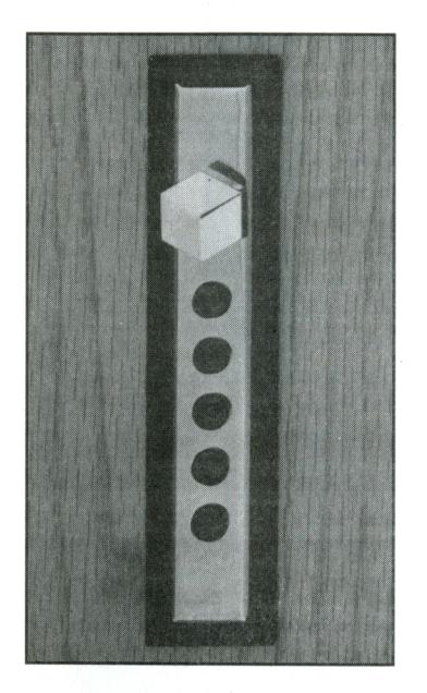
Congratulations! You have purchased a spring latch cabinet lock model C9602 from Simplex*/Ilco Unican*.
Please retain this instruction manual for future reference — it contains all instructions needed for changing the combination of your lock.
Your lock has a factory set combination common to all of our locks: press buttons 2 and 4 together, release; then press button 3, release. You must feel distinctive clicks to know the buttons are pressed properly.
Warning: For your own safety, you must change the combination at the time of installation.
Read all instructions before starting.
These instructions are for installations on wood doors 5/8" to 7/8" (16 mm to 22 mm) thick.
Since every installation is unique, check your door and frame carefully to be sure that the recommended procedures will not cause any damage. Simplex/ Ilco Unican is not responsible for any damage caused by installation.

"ILCO UNICAN
SIMPLEX®
- ® Ilco and Unican are registered trademarks.
- ® Simplex is a registered trademark.
Table of Contents
You will find the Templates in the middle of this booklet.
| Sī | ΓEPS | PA | AGE |
|---|---|---|---|
| 1 | Get Ready | ||
| Decide if you will use the trim plate | 1 | ||
| Tools required | 1 | ||
| 2 | Determine The Correct Lock Location | 2 | |
| 3 | Mark The Door | 3 | |
| 4A | Installation 'A' - (with trim plate) | ||
| Make the slot | 4 | ||
| Install the latch bolt guide | ∠ | ||
| Install the lock | 5 | ||
| Check the lock's operation | 5 | ||
| 4B | Installation 'B' - (without trim plate) | ||
| Make the slot | 6 | ||
| Install the latch bolt guide | 6 | ||
| Install the lock | 6-7 | ||
| Check the lock's operation | 7 | ||
| 5 | Install The Strike | 8 | |
| 6 | Install The Elbow Catch | ||
| 7 | Change The Combination | ||
| - |
Checklist
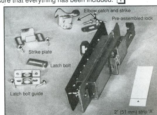
Use this checklist to make sure that everything has been included.

Latch bolt guide
Strike plate Elbow catch and strike
Pre-assembled lock: face plate, trim plate, chamber, back plate
Eight #5 1/2" (13 mm) screws
2 templates (in the middle of this booklet)
2" (51 mm) strip marked 'A'
Warranty Card
Get Ready
DECIDE IF YOU WILL USE THE TRIM PLATE
Two installation methods are possible: with or without the supplied trim plate.
(with trim plate)
INSTALLATION 'A'
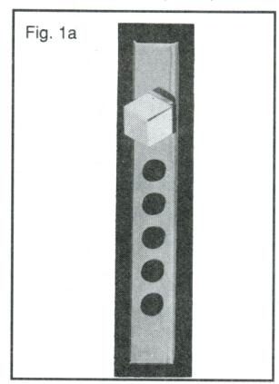
If you choose to use the trim plate, installation is simplified: you only need to cut a 1" (25 mm) slot and slide in the pre-assembled lock. (See fig. 1a)
(without trim plate)
STEP 1
INSTALLATION 'B'
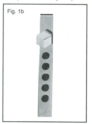
If you choose not to use the trim plate, you will need to use a router to mortise a two-step slot in the door, and partially disassemble the lock. (See fig. 1b)
TOOLS REQUIRED
- Pencil Ruler Tape Fine cut wood file
- Drill (variable speed is best) <sup>1</sup>/<sub>16</sub>" (1.6 mm) drill bit
- Scribe, awl, or sharp instrument for marking holes
- Small magnetic flathead screwdriver
For installation 'A' only
- 1" (25 mm) adjustable drill bit
- One of the following: Keyhole saw, copeing saw, or jig saw
For installation 'B' only
- Router with 1" (25 mm) and <sup>1</sup>/<sub>2</sub>" (13 mm) bits
- Woodworking clamps or vise
.
HOW THE LOCK FUNCTIONS
The locking mechanism works when the spring-loaded latch bolt engages behind the strike. (See fig. 2a)
The placement of the lock in the door is dependent on many factors:
- · Style of door
- · Relationship of door to frame
- · Existing ornamentation on door
Choose a position that allows proper strike engagement.
Note: Most installations are vertical, although horizontal placement is possible.
The lock must lie completely flat on a portion of the door that is " to " (16 mm to 22 mm) thick.
For best results, we recommend that you place the lock within 3" (76 mm) of the non-hinged side of the door.
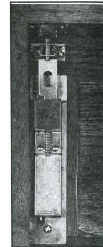
Fig. 2a
DETERMINE YOUR CABINET STYLE
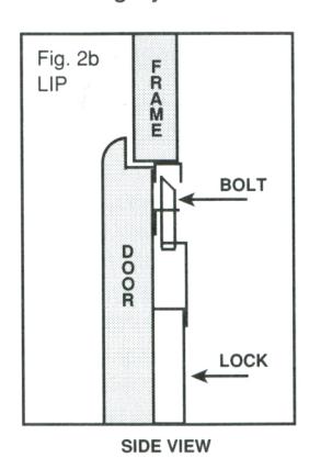
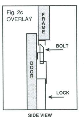
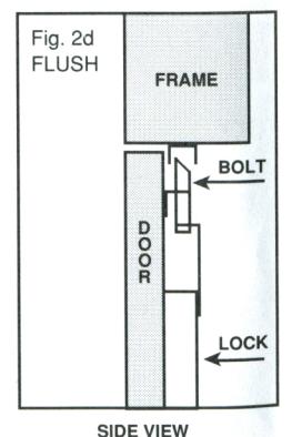
There are many cabinet styles, but most fit into the three categories shown below. Look at figures 2b (LIP), 2c (OVERLAY), and 2d (FLUSH), and choose the category that best resembles the way your door aligns with the frame:
FOR LIP (2b) OR OVERLAY (2c) DOORS
Take the 2" (51 mm) strip marked 'A' and the template for your installation ('A' or 'B'). Fold the 'A' strip on the black line.
Mark the Door
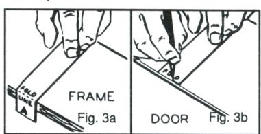
- Open door; place strip on frame with fold on edge of frame, short end bent inside. (See fig. 3a)
-
3. Secure strip in place, close door on strip. Mark where edge of door hits strip. (See fig. 3b)
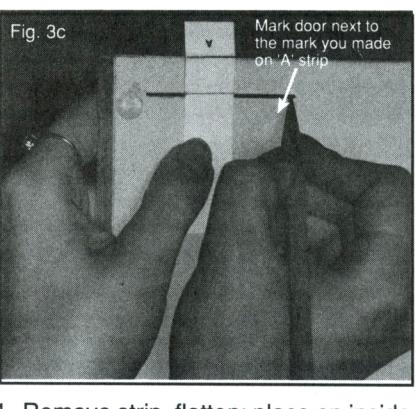
- Remove strip, flatten; place on inside of door. (See fig. 3c)
Fig.
- Place template on inside of the door so "edge of frame" line aligns with marks from 'A' strip. (See fig. 3d)
- Center your template at the vertical location you chose; secure template to door in this position.
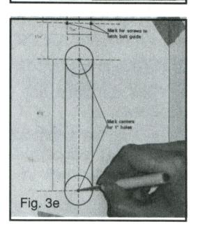
- 7. Mark two center holes for slot, and locations for two screws for the latch bolt guide. (See fig. 3e)
FOR FLUSH (2d) DOORS
- 1. Use the template for your installation ('A' or 'B').
- 2. If there is no gap between the top of the door and the edge of the frame, line up the template on the inside of the door so the "edge of frame" line aligns with the top edge of the door.
- 3. If there is a gap, measure the gap and compensate for it by moving the template up by an equivalent amount.
- Center your template at the vertical location you chose; secure template to door in this position.
- 5. Mark two center holes for slot, and locations for two screws for the latch bolt guide. (See fig. 3e)
MAKE THE SLOT
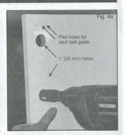
- 1. Use a 1/16" (1.6 mm) drill bit to drill two pilot holes for the screws to the latch bolt guide - do not drill completely through door.
- 2. Use a 1/16" (1.6 mm) drill bit to drill a small lead hole at each location marked for 1" (25 mm) holes - drill lead holes completely through door.
- 3. Using a 1" (25 mm) drill bit, follow lead holes, and drill halfway from front, and halfway from back to form two 1" (25 mm) holes. This procedure prevents chipping. (See fig. 4a)
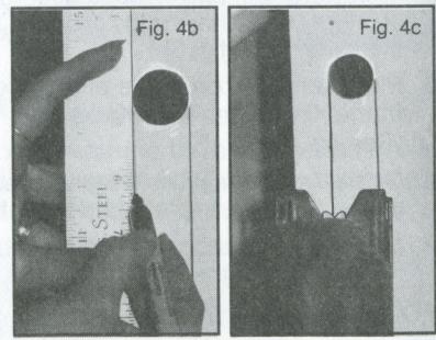
- 4. With pencil and ruler, draw two lines connecting the two 1" (25 mm) holes as shown on the template - these lines are your saw guidelines. (See fig. 4b)
- 5. Use a narrow fine tooth saw blade to cut along saw guidelines to make the slot. (See fig. 4c)
- 6. Measure slot; if needed, file to 1" (25 mm) width.
USE FINE TOOTH SAW TO REDUCE CHIPPING
INSTALL THE LATCH BOLT GUIDE
- 1. Take the latch bolt guide and two screws.
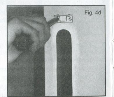
- 2. Secure the latch bolt guide to the inside of the door by fastening screws in the pilot holes. (See fig. 4d)
INSTALL THE LOCK
1. Take the lock and the latch bolt.
Installation 'A' — (with trim plate)
2. Remove both pieces of the back plate by removing 2 screws. (See fig. 4e)
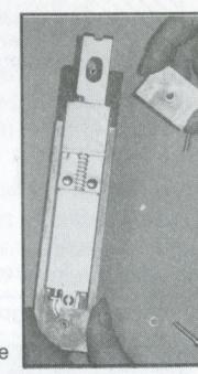
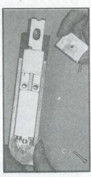
Make sure bevel edge is facing awarron door Make sure the legs o the back of the lock catch on the groove in the bottom of the latch bolt
- 3. Place the latch bolt in the latch bolt guide while holding the latch bolt with one hand, place the entire lock assembly into the slot with the other hand. (See fig. 4f)
- 4. Replace both pieces of the back plate.
- 5. The back plate should fit snugly in the slot; if not, file opening until back plate just fits.
- 6. Fasten the back plate with two screws.
- 7. Look at lock from the front of cabinet; make any alignment adjustments needed.
CHECK THE LOCK'S OPERATION (with the door open)
- 1. Turn the knob left until it stops do not force; release.
- 2. Enter the preset combination: press buttons 2 and 4 at the same time; release, press button 3; release. You must feel distinctive clicks to know the buttons are depressed correctly.
- 3. Turn the knob right until it stops the latch bolt should retract, compressing the spring. If not, repeat steps 1 and 2. Release the knob. The spring should return the latch to its locked position.
GO TO PAGE 8 (Step 5) - INSTALL THE STRIKE
MAKE THE SLOT
- Use a <sup>1</sup>/16" (1.6 mm) drill bit to drill two pilot holes for the latch bolt guide - do not drill holes completely through door.
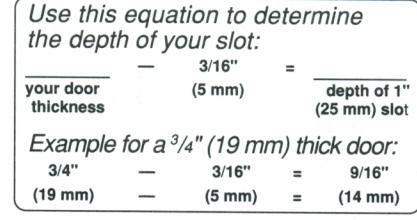
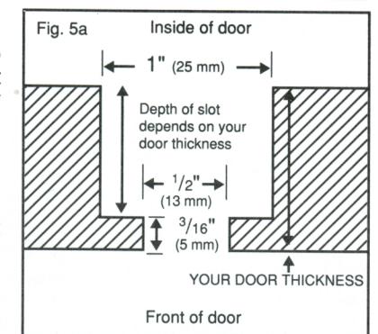
- 2. Determine the depth of the 1" (25 mm) wide slot:
Measure the thickness of your door. You must leave <sup>3</sup>/<sub>16</sub>" (5 mm) of the front of the door (See fig. 5a).
- 3. Route out the 1" (25 mm) wide slot on the inside of the door.
- Turn door over; route a <sup>1</sup>/<sub>2</sub>" (13 mm) wide slot on the front of the door for the lock face plate.
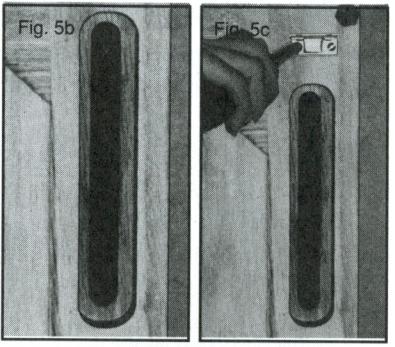
See figure 5b for a finished slot.
INSTALL THE LATCH BOLT GUIDE
- Take the latch bolt guide and two screws.
- Secure latch bolt guide to inside of door by fastening screws in the pilot holes. (See fig. 5c)
INSTALL THE LOCK
- 1. Take the lock and latch bolt.
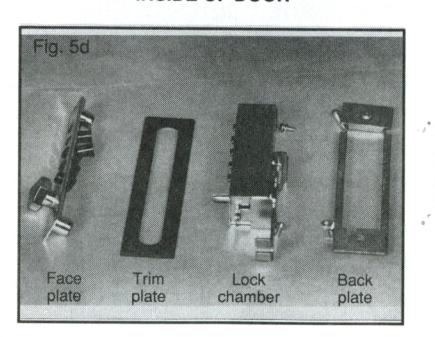
- Partially disassemble the lock by removing both pieces of the back plate, the face plate, and the trim plate. Put aside the trim plate. (See fig. 5d)
Note: Don't worry if all the buttons fall out - you'll replace them later.
CUT-AWAY TOP VIEW OF DOOR SLOT
INSIDE OF DOOR
Installation 'B' — (without trim plate)
INSTALL THE LOCK (cont'd)
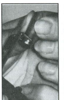
- Line up the grooves on the bottom of the latch bolt with the legs on the back of the lock chamber. (See fig. 5e)
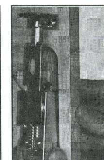
- Manoeuvre the latch bolt into the latch bolt guide while placing the lock chamber into the slot. (See fig. 5f)
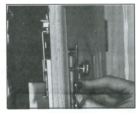
- Replace buttons in the face plate; align face plate on outside of door over lock chamber. (See fig. 5g) Fasten face plate in place with 2 screws.
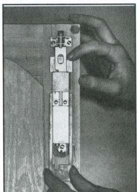
- Replace both pieces of the back plate. (See fig. 5h) Back plate should fit snugly in slot - if not, file slot until back plate just fits. Fasten back plate in place with 2 screws.
- Look at lock from the front of cabinet; make any alignment adjustments needed.
CHECK THE LOCK'S OPERATION (with the door open)
- 1. Turn the knob left until it stops do not force; release.
- 2. Enter preset combination: press buttons 2 and 4 at the same time; release, press button 3; release. You must feel distinctive clicks to know the buttons are pressed correctly.
- Turn the knob right until it stops the latch should retract, compressing the spring. If not, repeat steps 1 and 2. Release the knob. The spring should return the latch to its locked position.
Note: It may be necessary to loosen the screws holding the face plate to the lock chamber.
Install the Strike STEP 5
- 1. Take the strike and two screws.
- 2. Close the door; mark the location where the latch bolt hits the frame. (See fig. 6a)
NOTE: This step can be tricky - you may have to lean inside of your cabinet to see where the latch bolt touches the frame.
3. Mark locations for the two screws.
NOTE: Take a minute to look at how far back in the frame the strike should go. For instance,

- 4. Use a 1/16" (1.6 mm) bit to drill pilot holes for the screws.
- 5. Mount the strike by fastening the screws.
- Close the door if the latch bolt does not engage behind the strike, loosen screws, and slide the strike along its elongated slots to a new position.
- 7. Repeat until latch bolt engages properly.
The door is now locked.
To unlock door, turn the knob left until it stops - do not force; release. Enter preset combination: press buttons 2 and 4 at the same time; release; press button 3; release. You must feel distinctive clicks to know the buttons are pressed correctly.
Turn the knob right and pull door open.
Install the Elbow Catch
STEP 6
Fig. 6a
You must install the elbow catch if your cabinet has double doors.
- 1. Take elbow catch, strike, and 4 screws.
- 2. Mark where the frame hits the inside of the second door.
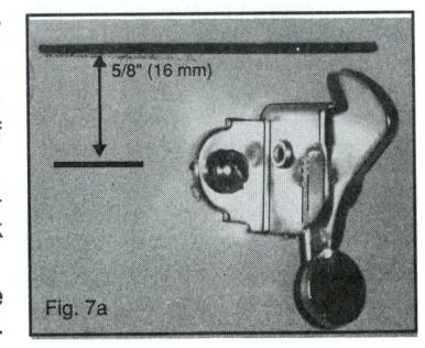
- Install the catch so the screws are approximately 5/8" (16 mm) below the mark you just made. (See fig. 7a)
- 4. Install the strike on the underside of the frame in a position to engage the catch.
Change the Combination
STEP 7
You must change the combination of your lock after installation to be sure that your combination is private.
You can easily change to a new combination using any number of buttons you wish in any order. You can push two or more buttons at the same time as a step in your combination. Each button can only be used once in the combination.
Choose your new combination and write it down.
Perform the following operations with the DOOR OPEN:
- 1. Turn the knob left until it stops do not force; release.
- Enter the existing combination. If this is your first time, then the existing combination is factory set: press buttons 2 and 4 at the same time; release, press button 3; release. You must feel distinctive clicks to know that the buttons are pressed correctly.
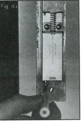
- Put a small screwdriver in the notch in the back plate of the lock, and push the slide into the lock as far as it will go. (See fig. 8a) Remove screwdriver.
- 4. Turn the knob left to clear out the old combination. Release knob.
- Enter your new combination carefully be sure to feel the distinctive clicks to know that the buttons are pressed correctly.
- 6. Turn the knob right to set your new combination.
-
7. Try your new combination (keep door open)
-
a. Turn knob left until it stops
- do not force; release.
- b. Enter your new combination.
- Turn knob right latch bolt should retract, compressing the spring.
-
a. Turn knob left until it stops
8. Make sure your combination is set properly
- a. Turn knob left until it stops do not force; release.
- b. Enter any wrong combination.
- c. Try to turn the knob right knob should not turn.
- d. If knob turns, it means there is no combination entered; turn knob left; release; go back to step 3 to set your combination.
The UNICAN Group Pushbutton Lock Marketing Network
NORTH AMERICA
SIMPLEX ACCESS CONTROLS
2941 Indiana Ave., Winston Salem, N.C. 27105 U.S.A.
Tel.: (919) 725-1331 Fax: (919) 725-3269
CANADA:
ILCO UNICAN INC. - Dominion Lock Div.
7301 Decarie Blvd., Montreal, Quebec H4P 2G7 Canada
Tel.: (514) 735-5411 Fax: (514) 735-8707
MEXICO:
ILCO / IUSA S.A. de C.V.
Viaducto Rio de la Piedad No. 525-D Col. Granjas, C.P. 08400, Mexico D.F. Mexico Tel.: (52) 5-654-7213 Fax: (52) 5-654-7356
PACIFIC RIM
AUSTRALIA:
ILCO UNICAN AUSTRALIA (PTY) LTD.
(Sydney Office)
P.Ó. Box 569 Willoughby, N.S.W. 2068, Australia Tel.: (61) 2-417-4544 Fax: (61) 2-417-6049
JAPAN:
UNIKIS JAPAN CO. LTD.
11-14 Minami-Senba, 4 Chome, Chuo-Ko, Osaka 542, Japan
Tel.: (81) 6-244-0385 Fax: (81) 6-251-4045
EUROPE
FRANCE:
ILCO UNICAN (FRANCE) S.A.
16, rue du Moulin des Bruyères 92400 Courbevoie, France Tel.: (33) (1) 47 89 11 96 Fax: (33) (1) 47 88 86 29
ITALY:
ORION S.P.A.
Via Mercatelli Sant Anna 6, 31030 Colfosco di Susegana - (TV), Italy Tel.: (39) 438-780155 Fax: (39) 438-781088
SWITZERLAND:
ILCO UNICAN S.A.
3 rue Ami-Lullin, P.O. Box 384 CH-1211, Geneva 3 Switzerland
Tel.: (41) 22-736-9920
Telex: 413 307 fidag (attn. ILCO)
Fax: (41) 22-786-8158