Securitron PB3, PB3A, PB3N, PB3AN Push Buttons Operating Manual
Open the original PDF document
View PDF

ASSA ABLOY
SECURITRON PB3, PB3A, PB3A, PB3AN EXIT BUTTON INSTALLATION AND OPERATING INSTRUCTIONS
1. DESCRIPTION
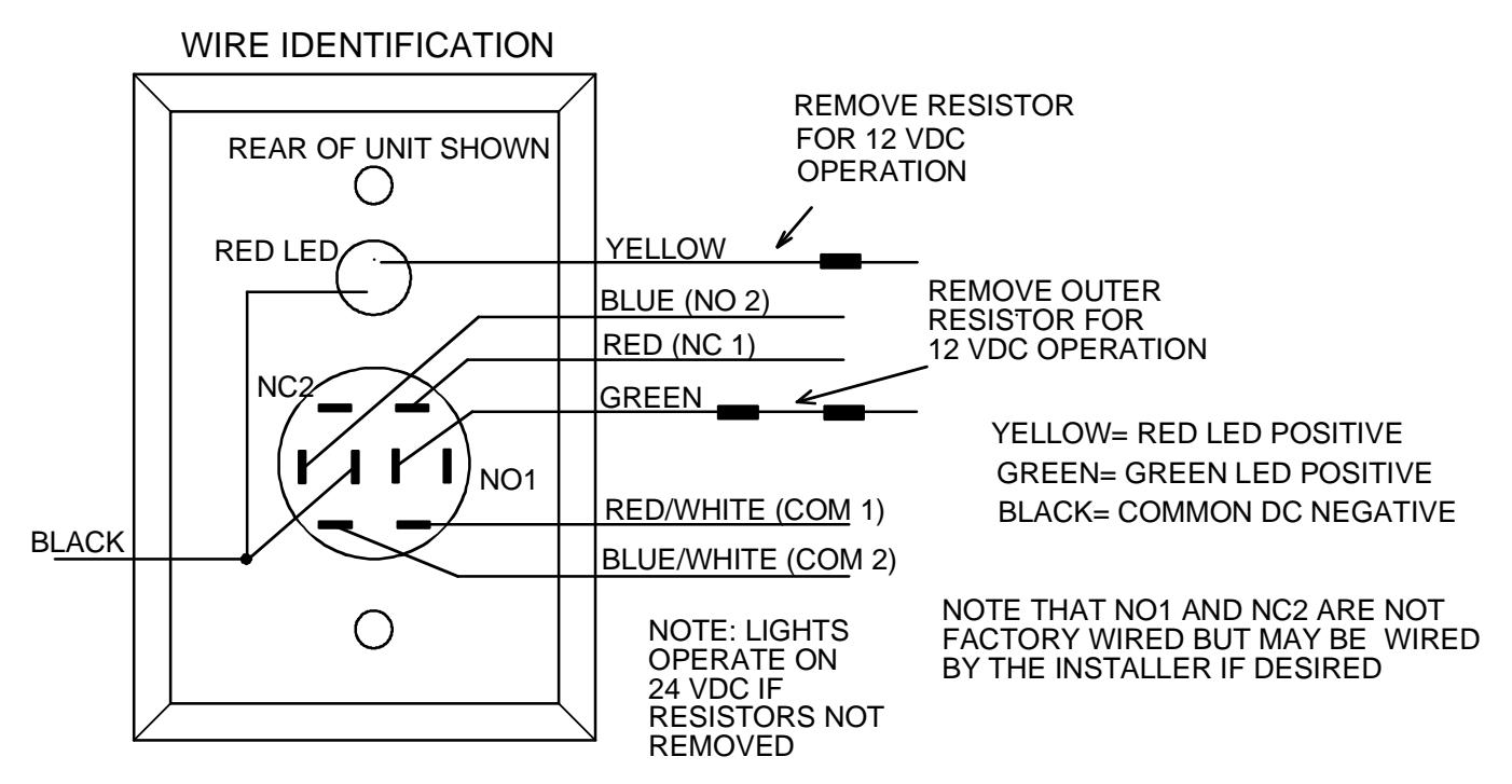
The model PB3 is a spring loaded momentary rectangular exit button, with bi-color illumination, mounted on a stainless steel single gang outlet box cover. The model PB3A is alternate action (push-on; push off). Adding "N" to the part #(PB3N, PB3AN) yields mounting on a 1 3/4" narrow stile plate. The NO and NC (DPST) contacts switch when the button is depressed and return when it is released. The switch is UL listed with 3 AMP capacity. Note that the switch type is double pole double throw. Two of the contacts are not factory wired (see drawing below). The reason for this is that all six contacts are rarely required and providing less factory wiring makes for a less crowded hookup. The installer may use these contacts by soldering leads to them.
The red and green lamps can be individually operated according to the needs of the installation. The red lamp is an LED mounted above the button and the green lamp is an LED, illuminating the button itself. The PB3 can be used for momentary release of fail safe or fail secure electric locks. If interfaced with a release hold timer, such as Securitron's TimeMate, it can provide for timed release of electric locks. It may also be used to input a REX (request to exit) signal to a card reader system. We recommend that the local building or fire safety authority be consulted prior to using exit buttons for door egress. They may require a "no special knowledge" exit device such as Securitron's Touch Sense Bar.
2. INSTALLATION
The PB3 comes with a retro-fit mounting device and color coded hookup wires installed. The drawing below shows the unit's connection points.
3. LAMP OPERATION
Resistors are installed so that the lamps may be operated on either 12 or 24 VDC. The yellow wire drives the red LED and the green wire drives the green LED. The yellow wire has a single resistor soldered in line and the green wire has two resistors soldered in line. If the power supply is 24 VDC, connect directly to the wires. If the power supply is 12 VDC, remove the resistor on the yellow wire and the outer resistor on the green wire for proper operation at the lower voltage.
The red indicator draws 20 mA at either voltage. For replacement: the red indicator LED is Securitron's part number 700-10095 the switch LEDs are listed in the table below.
| Switch Green LED | 030-11000 |
|---|---|
| Switch Red LED | 030-11030 |
4. WIRING
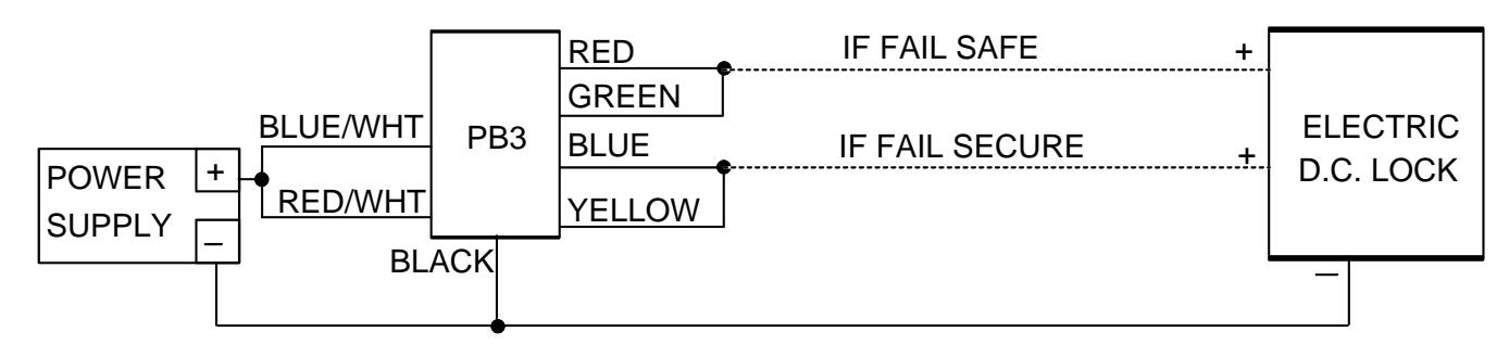
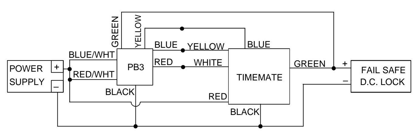
The drawings below show two common applications. The first shows momentary release of a fail safe or fail secure electric lock. The PB3 indicators are connected so that the switch LED is normally on. When the button is pressed, releasing the lock, the switch LED turns off and the Keyplate indicator comes on. The second drawing shows timed release of a fail safe electric lock using the PB3 and Securitron's TimeMate. Momentarily pressing the button will release the lock for the amount of time set on the TimeMate. The Switch LED will switch off and the keyplate LED illuminates during the lock release period. The wiring is also done in double break fashion so that even if the timer fails, the button will still be able to momentarily release the lock. This is for added safety.
MOMENTARY RELEASE OF FAIL SAFE OR FAIL SECURE ELECTRIC LOCK
TIMED DOUBLE BREAK RELEASE OF FAIL SAFE LOCK
5. ALTERNATE LENS CHANGING
The pushbutton is factory shipped with a green lens set installed and an optional red lens set. Changing to the Red set is simple
- 1) While holding the keyplate grasp the top and bottom of the lens and pull straight out from the keyplate.
- 2) To remove LED use a fine-nosed pliers and grasp LED by the sides and pull straight out.
- 3) To replace the LED. Look at the back of LED and locate the flat section on the LED circumference. The flat section will go up when inserting the LED into the switch. With fine-nosed pliers grasp the edges of the LED from the front side of the LED, lineup the LED terminals with the socket in the switch and gently push the LED into the switch.
4) Place the lens over the switch face confirm that the text on the lens is right reading to the keyplate and push down completely until it snaps into place. Depress lens several time to ensure smooth operation and that the lens is not binding.
PN# 500-15100 Rev. D, 02/12
Flat section