Securitron M380E Magnetic Lock Installation Instructions
Open the original PDF document
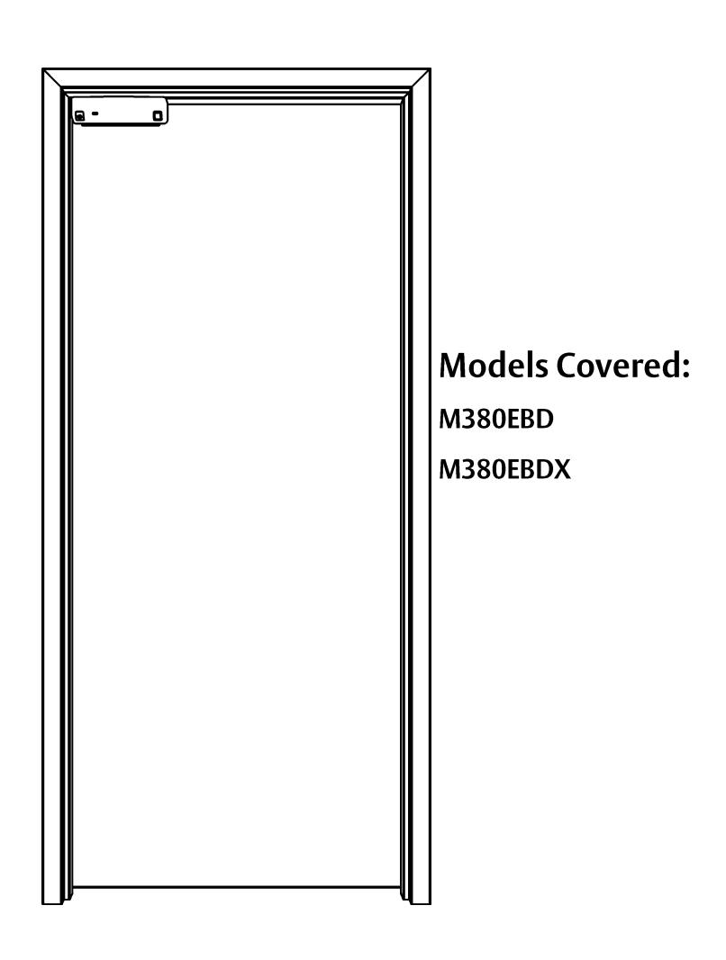
View PDFSecuritron® M380E Series Magnalock® With EcoMag® Technology
ASSA ABLOY
Installation Instructions
Experience a safer and more open world

| RECOMMENDED INSTALLATION TOOLS | 3 |
|---|---|
| IN THE BOX CONTENTS | 3 |
| Installation Hardware Pack Contents | 4 |
| Strike Installation Hardware Pack Contents | 4 |
| SPECIFICATIONS | 5 |
| MAGNALOCK PREPARATION AND INSTALLATION | 5 |
| Performing a Pre-Installation Survey | 5 |
| Removing the Cover | 6 |
| Positioning the PIR REX Module in the Magnalock | 6 |
| Preparing the Magnalock | |
| Installing Magnalock on a Metal Door Frame | 9/10 |
| Installing Magnalock on a Wood Door Frame | 9/14 |
| Assembling the Lock to the Bracket and Adjusting, as Necessary | 17 |
| MAGNALOCK ELECTRICAL INSTALLATION | |
| Preparing the Magnalock | 18 |
| Locating and Setting the Dip Switches on the Magnalock | 19 |
| Magnalock Operation with Access Control System | 20 |
| Magnalock Operation with Local Control | 20 |
| Locating and Setting the Jumpers on the Magnalock | 20 |
| Documenting the Configuration Settings | 21 |
| Pulling the Wiring | 22 |
| Connecting the Final Wiring | 22 |
| Dual Lock (Double Door) Wiring | 24 |
| Performing Initial Calibration | 26 |
| Verifying PIR Coverage and Adjusting the PIR Coverage, as Needed | 26 |
| Re-Installing the Lock Cover | 28 |
| TROUBLESHOOTING | 29 |
| LED Behavior | 29 |
| Returning the Magnalock to Factory Default Settings | 29 |
| MADDANITY | 21 |
RECOMMENDED INSTALLATION TOOLS
Masking Tape Measuring Device #1 and #2 Phillips Screwdrivers
Mini Phillips Screwdriver 1/2" Open End or Crescent Wrench, Wire Strippers/Cutter
or Blind Nut Installation Tool
Pencil/Pen Center Punch 3/16" Hex (Allen) Wrench
Multimeter Fish Tape or Lead Wire
Rubber Mallet Drill Bits: #36 (0.107"), 3/16", 7/32", 3/8", 1/2", and 5/8"
IN THE BOX CONTENTS
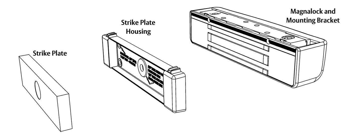
Installation Hardware Pack
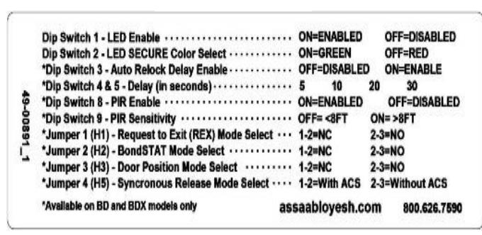
Settings Label
Strike Installation Hardware Pack
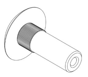
Sex Bolt
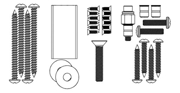
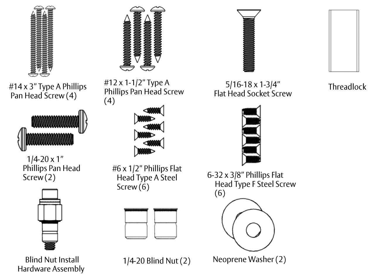
Installation Hardware Pack Contents
NOTE: Hardware is provided for various installations. There will be leftover parts depending on the type of installation.
Strike Installation Hardware Pack Contents


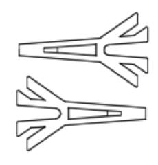
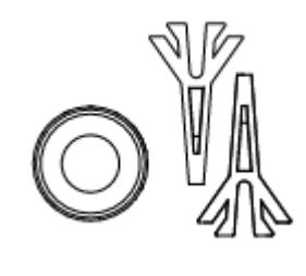
Template Pins (2)
SPECIFICATIONS
Mechanical
Physical Size: Height: 2.20" [56 mm]
Depth: 2.45" [62 mm] Length: 10.00" [254 mm]
Shipped Weight: 6.5 lb [2.95 kg]
Static Holding Force (Maximum): 600 lbs [272 kg]
UL Tested Ratings: Static Holding Force: 500 lbs [227 kg]
Dynamic Holding Force: 50 ft-lbs [68 |] Endurance: 250,000 cycles
Electrical
IMPORTANT: UL 294 compliance requires that the locking device be powered by a UL 294 (ALVY) or UL 603 (APHV) listed
power supply and shall be installed in accordance with the following UL and National Standards:
NFPA 70 – National Electrical Code
Input Voltage: 12 through 24 VDC. Power must be at least rectified and (VDC +/- 10%)
filtered to meet minimum electrical specifications. AC, Half Wave, and Full Wave power is unacceptable.
Voltage – 30 VDC (Maximum) (Resistive) Tamper Rating:
Current – 1A (Maximum)
DPS Rating: Voltage – 30 VDC (Maximum) (Resistive)
Current – 125 mA (Maximum)
Voltage - 24 VDC REX Rating:
Current – 1A (Resistive)
Current by Model Number Average Power Draw Maximum Power Draw
(12/24VDC) (12/24 VDC)
M380EBD 140/90 mA 585/310 mA 150/100 mA 610/320 mA M380EBDX
IMPORTANT: Size your power supply to handle the UL verified maximum power draw.
Environmental (Indoor Use)
Operating Temperature: 32°F to 110°F [0°C to 43°C]
Humidity: 10% to 90% RH
IMPORTANT: This product must be installed according to all applicable building and life safety codes.
UL 294 Performance levels: Access Control Line Security Level 1, Destructive Attack Level 1, Endurance Level IV, Standby Power Level 1.
MAGNALOCK PREPARATION AND INSTALLATION
Performing a Pre-Installation Survey
-
Before installing the Magnalock, DETERMINE and ASSESS the mounting location for the following:
- Physical strength of the frame—it should be strong enough to meet or exceed the holding force of the Magnalock.
- Frame and vicinity—it should offer protection for the wiring to prevent vandalism, and adequate protection from rain exposure.
5 500-24085 2
- Door inspection—it should be inspected for any obstacles that may interfere when mounting the strike plate.
- Proper mounting—The Magnalock comes with factory default mounting for use with an outswing door. ASSA ABLOY ESH should be contacted for available brackets for other installation configurations.
Removing the Cover
NOTE: Removing the cover provides access to the circuit board on the back of the magnet.
- 1. Using a Phillips screwdriver, REMOVE the two (2) screws securing the cover, as shown in Figure 1, "Removing the Cover Screws."
- 2. SET the screws aside to re-attach the cover later.
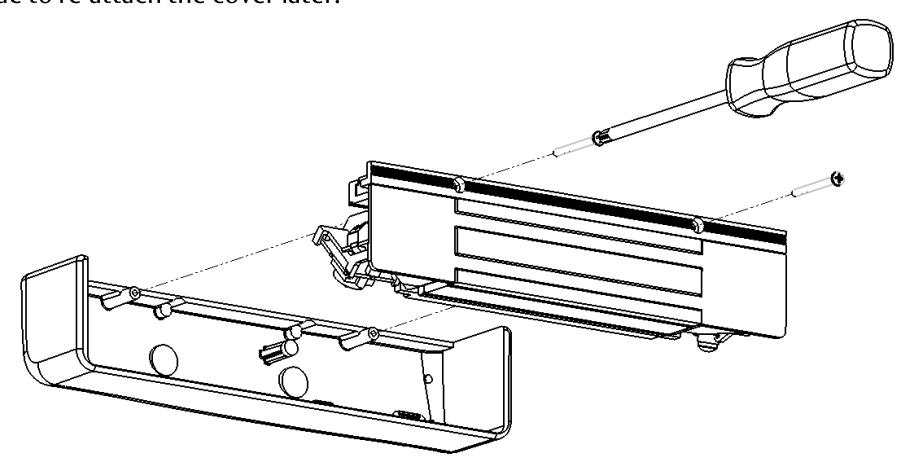
Figure 1. Removing the Cover Screws
Positioning the PIR REX Module in The Magnalock
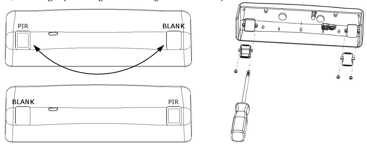
NOTE 1: The physical position of the PIR REX module of a M380EBDX model may be reconfigured for either end of the Magnalock, as desired.
1. To remove or install the module, compress the legs of the support bracket and slide the bracket into or out of the retaining rails at either end of the lock (see Figure 2, "Removing and Installing the PIR REX Module").
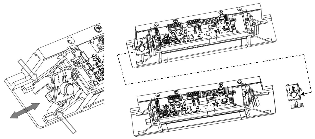
Figure 2. Removing and Installing the PIR REX Module
2.
1.
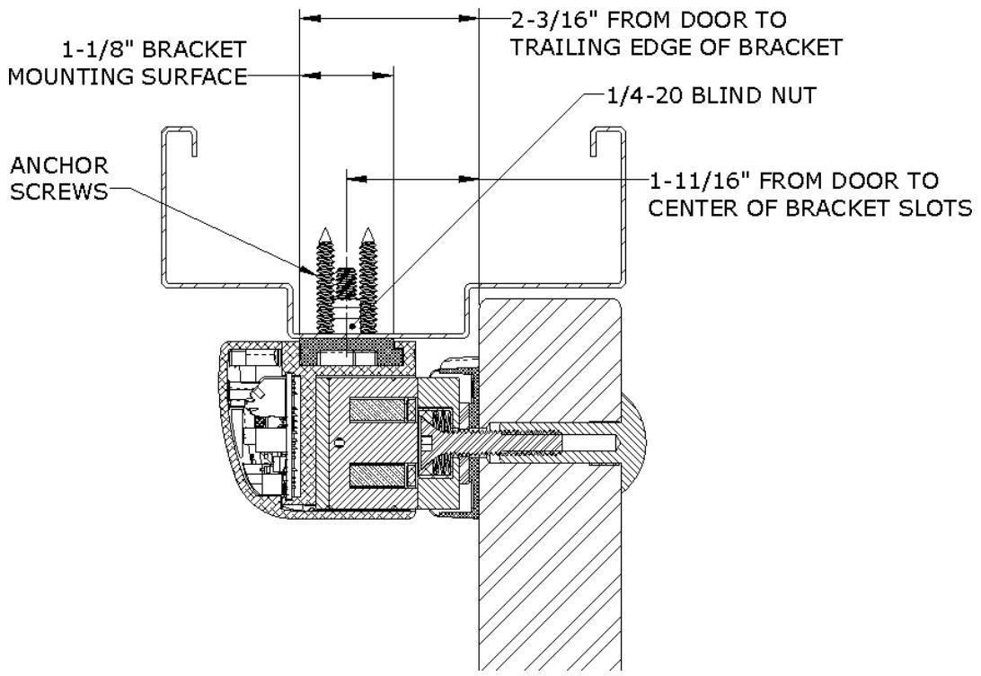
Figure 4. Assessing the Installation Site
2. REMOVE the two (2) screws securing the lock to the mounting bracket and SLIDE the bracket from the top of the lock chassis (see Figure 5, "Removing the Securing Screws").
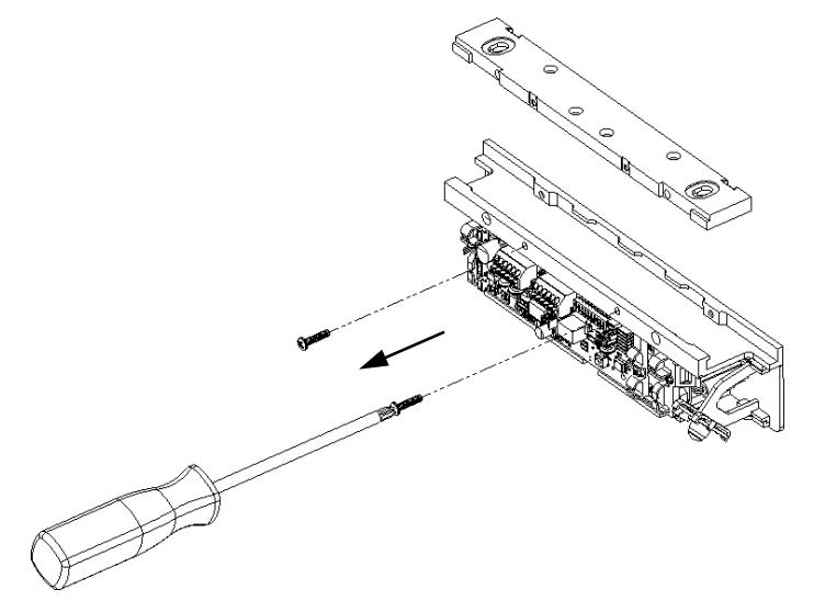
Figure 5. Removing the Securing Screws
3. PINCH and INSERT the template pins flush into the dovetail slots of the mounting bracket (see Figure 6, "Inserting the Template Pins").
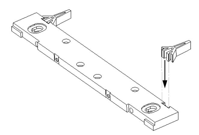
Figure 6. Inserting the Template Pins
-
4. PERFORM the following to mark the mounting holes:
- a. APPLY masking tape to the door and frame surfaces to protect from any possible damage during marking and drilling.
- b. PLACE the mounting bracket on the secure side of the door against the frame stop and towards the side of the door that does not have hinges, and has a minimum of 1" clearance from the frame.
- c. CLOSE the door and ADJUST the bracket so that the template pins rest against the door.
d. MARK the frame through the two (2) oblong bracket mounting holes (see Figure 7, "Marking the Frame").
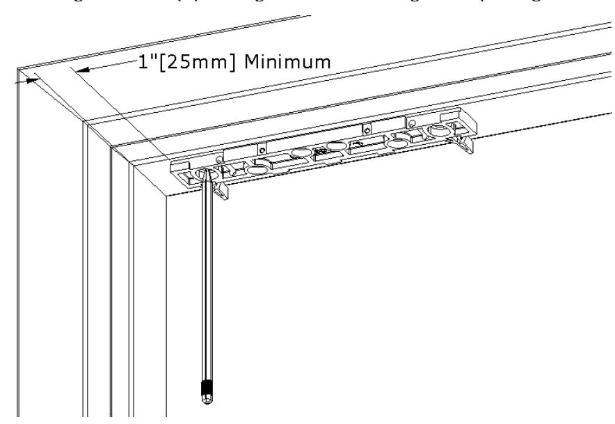
Figure 7. Marking the Frame
5. MARK the frame for wire feed-through hole at the end closest to where the wire run will be accessed, and ENSURE the hole marking is centered at least 5/16" from the end (see Figure 8, "Position of Wire Feed-Through Holes").
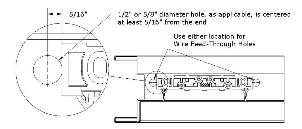
Figure 8. Position of Wire Feed-Through Holes
6. REMOVE mounting bracket from frame.
INSTALLING MAGNALOCK ON A METAL DOOR FRAME
1. GO TO "Installing Magnalock on a Metal Door Frame" section.
INSTALLING MAGNALOCK ON A WOOD DOOR FRAME
1. GO TO "Installing Magnalock on a Wood Door Frame" section.
Installing Magnalock on a Metal Door Frame
NOTE: Drilling a pilot hole first or using a step bit will ensure a snug fit for the blind nuts.
1. DRILL two (2) 3/8" diameter holes at bracket-mounting hole marks (see Figure 9, "Drilling the Bracket Mounting Holes"); DO NOT oversize.
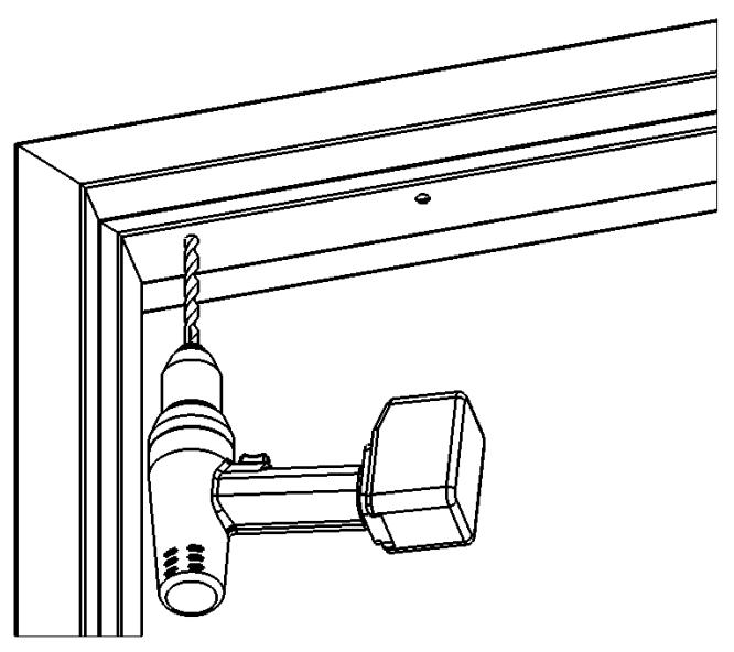
Figure 9. Drilling the Bracket Mounting Holes
- NOTE 1: Blind nuts provide a highly secure and tamper resistant system for mounting and are the mounting hardware provided for this unit.
- NOTE 2: A blind nut installation tool (Securitron BPT-2, "Blind Nut Placement Tool," or by others) can be used instead of using the open end wrench and hex wrench.
-
2. INSTALL blind nut into each 3/8" diameter hole using the provided tool (see Figure 10, "Installing the Blind Nuts").
- a. HOLD the collapsing nut with a 1/2" open end wrench.
- b. MAINTAIN pressure on the mounting surface, TIGHTEN the cap screw using a 3/16" hex wrench, and COLLAPSE the blind nut.
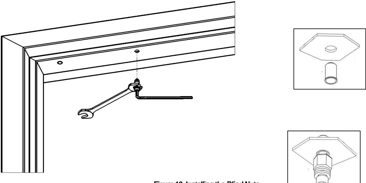
Figure 10. Installing the Blind Nuts
3. DRILL wire access holes (1/2" diameter recommended), as needed, on one or both sides of the bracket (see Figure 11, "Drilling the Wire Access Holes").
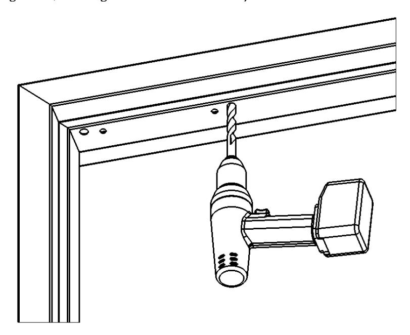
Figure 11. Drilling the Wire Access Holes
- 4. REMOVE the protective tape from the frame.
-
5. Temporarily INSTALL the mounting bracket with template pins against the closed door using a Phillips screwdriver (see Figure 12, "Installing the Bracket").
- a. USE two (2) 1/4-20 X 1" Phillips Pan Head Screws.
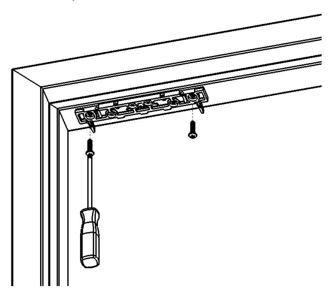
Figure 12. Installing the Bracket
6. With the door closed, ALIGN the strike plate housing with the template pins, as indicated on the strike plate housing. Ensure the strike plate housing is pushed snug against the template pins.
7. MARK the strike plate housing hole locations (see Figure 13, "Marking the Strike Plate Housing Hole Locations").
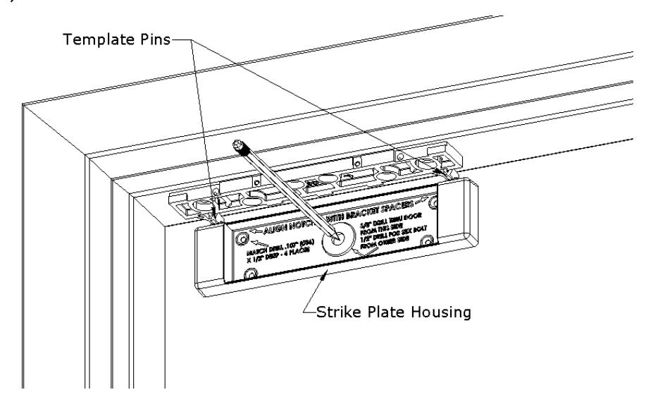
Figure 13. Marking the Strike Plate Housing Hole Locations
8. REMOVE the strike plate housing from the door, and the template pins from the top mounting bracket.
From INSIDE the door:
- 9. DRILL a 3/8" diameter hole for the Sex Bolt all the way through the door at the strike mounting center mark.
- 10. DRILL four (4) #36 (0.107)" x 1/2" deep holes for the strike plate housing anchor screws.
From OUTSIDE the door:
11. For a Hollow Metal Door , DRILL out the 3/8" diameter strike mounting hole to 1/2" diameter in the outer wall only (see Figure 14, "Drilling the Outside Door Holes").
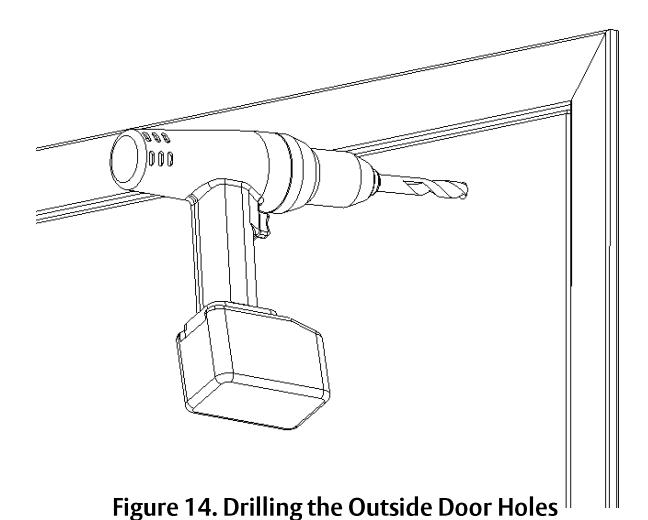
NOTE: Figure 15, "Installing the Strike Plate Assembly," Figure 16, "Strike Plate Assembly Installed – Inside Door," and Figure 17, "Strike Plate Assembly Installed – Outside Door," provide illustration for the following steps.
-
12. PERFORM the following to secure strike plate assembly to the door:
- a. INSERT the Sex Bolt into the hole from outside of the door.
- b. ATTACH the strike plate housing using the four (4) 6-32 x 3/8" Phillips flat head screws.
- c. APPLY the included thread lock compound, per manufacturer's specifications, to the 5/16-18 X 1-3/4" flat head socket screw.
- d. INSERT the 5/16-18 X 1-3/4" flat head socket screw through the strike bushing, strike plate, one (1) neoprene washer, strike plate housing and door into the Sex Bolt.
- NOTE 1: Strike should rock on the neoprene washer for proper function and optimal holding force.
- NOTE 2: The assembly should <u>not</u> be over-tightened; the neoprene washer should <u>not</u> be compressed; and the head of the 5/16-18 X 1-3/4" flat head socket screw should only be seated flush in the strike plate bushing.
- e. TIGHTEN the screw into the Sex Bolt using a 3/16" hex wrench; and while tightening, gently TAP the head of Sex Bolt using a rubber mallet until the head sits flush with the door. IF using a metal hammer, ensure the finish of the Sex Bolt is protected by additional material such as foam or cloth.
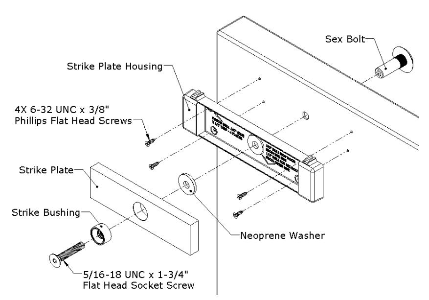
Figure 15. Installing the Strike Plate Assembly
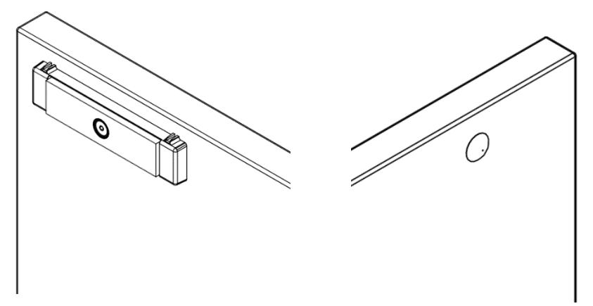
Figure 16. Strike Plate Assembly Installed – Inside Door Figure 17. Strike Plate Assembly Installed – Outside Door
13. GO TO "Assembling the lock to the Bracket and Adjusting, as Necessary" section.
Installing Magnalock on a Wood Door Frame
- 1. DRILL two (2) 3/16" diameter mounting holes by 1-1/4" deep at bracket-mounting hole marks (see Figure 18, "Drilling the Mounting Holes").
- 2. DRILL wire access holes (1/2" diameter recommended), as needed, on one or both sides of the bracket (see Figure 19, "Drilling the Wire Access Holes").
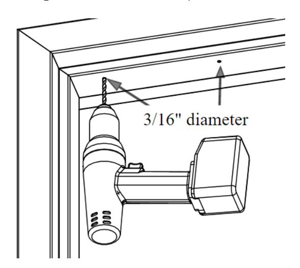
Figure 18. Drilling the Mounting Holes
Figure 19. Drilling the Wire Access Holes
- 3. REMOVE the protective tape from the frame.
-
4. Temporarily INSTALL the mounting bracket with template pins against the closed door using a Phillips screwdriver (see Figure 20, "Installing the Bracket").
- a. USE two (2) #12 X 1-1/2" Type A, Phillips Pan Head Screws.
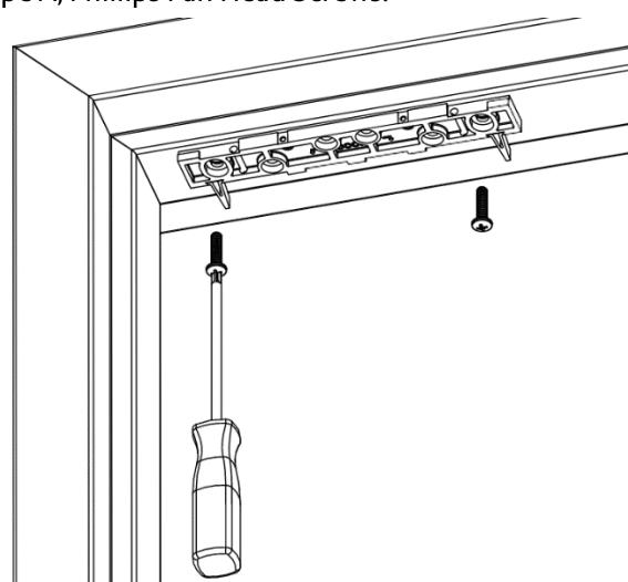
Figure 20. Installing the Bracket
5. With the door closed, ALIGN the strike plate housing with the template pins, as indicated on the strike plate housing.
6. MARK the strike plate housing hole locations (see Figure 21, "Marking the Strike Plate Hole Locations").
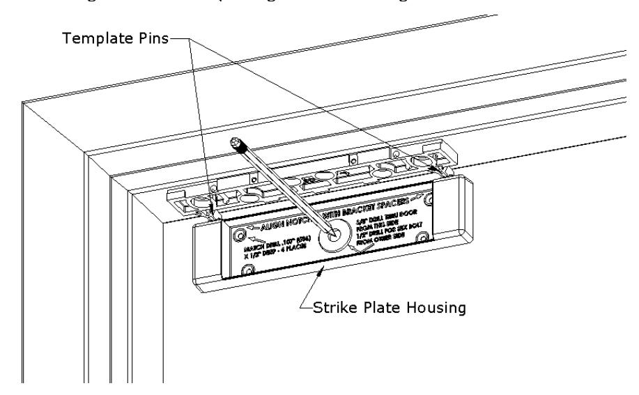
Figure 21. Marking the Strike Plate Hole Locations
7. REMOVE the strike plate housing from the door, and the template pins from the top mounting bracket.
From INSIDE the door:
- 8. DRILL a 3/8" diameter hole for the Sex Bolt all the way through the door at the strike mounting center mark.
- 9. DRILL four (4) #36 (0.107)" x 1/2" deep holes for the strike plate housing anchor screws.
From OUTSIDE the door:
10. DRILL out 3/8" diameter strike mounting hole to 1/2" diameter; DRILL completely through door.
NOTE: Figure 22, "Installing the Strike Plate Assembly," Figure 23, "Strike Plate Assembly Installed – Inside Door," and Figure 24, "Strike Plate Assembly Installed – Outside Door," provide illustration for the following steps.
-
11. PERFORM the following to secure strike plate assembly to the door.
- a. INSERT the Sex Bolt into the hole from outside of the door.
- b. ATTACH the strike plate housing using the four (4) #6 x 1/2" Phillips flat head screws.
- c. APPLY the included thread lock compound, per manufacturer's specifications, to the 5/16-18 X 1-3/4" flat head socket screw.
- d. INSERT the 5/16-18 X 1-3/4" flat head socket screw through the strike bushing, strike plate, one (1) neoprene washer, strike plate housing and door into the Sex Bolt.
- NOTE 1: Strike should rock on the neoprene washer for proper function and optimal holding force.
- NOTE 2: The assembly should not be over-tightened; the neoprene washer should not be compressed; and the head of the 5/16-18 X 1-3/4" flat head socket screw should only be seated flush in the strike plate bushing.
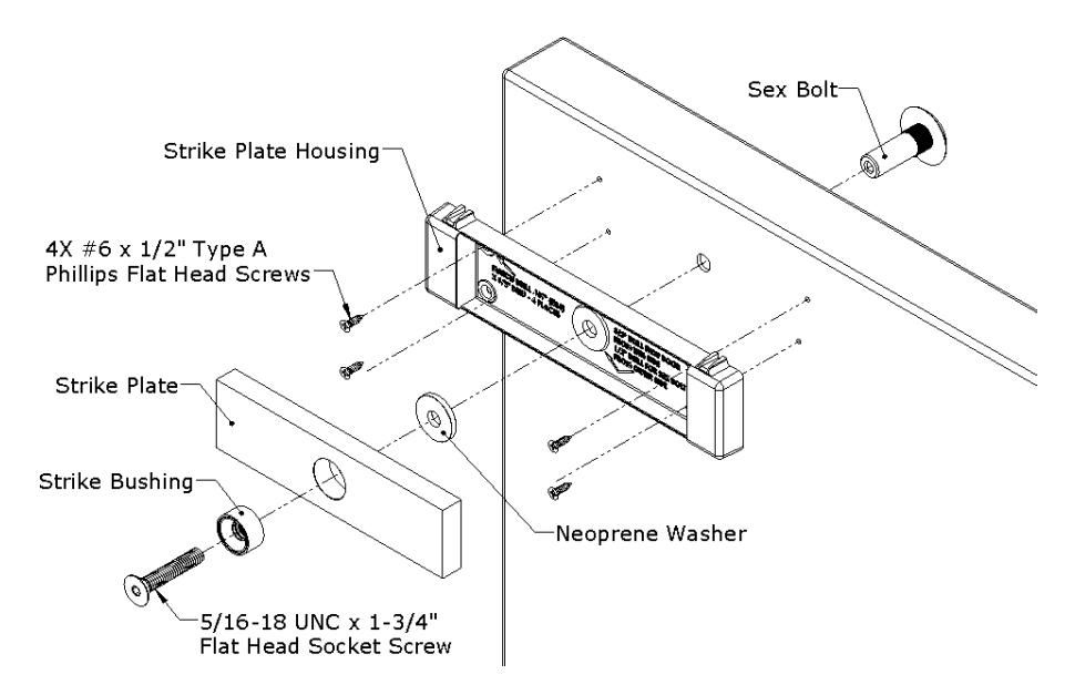
Figure 22. Installing the Strike Plate Assembly
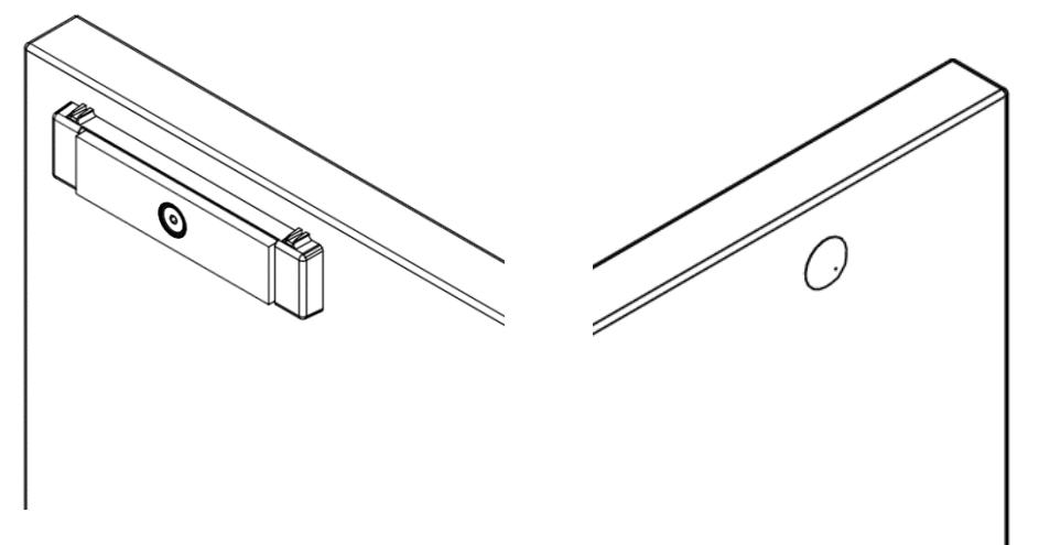
Figure 23. Strike Plate Assembly Installed – Inside Door
Figure 24. Strike Plate Assembly Installed – Outside Door
-
e. TIGHTEN the screw into the Sex Bolt using a 3/16" hex wrench; and while tightening, gently TAP the head of Sex Bolt using the rubber mallet. IF using a metal hammer, ensure the finish of the Sex Bolt is protected by additional material such as foam or cloth.
- 12. GO TO "Assembling the lock to the Bracket and Adjusting, as Necessary" section.
Assembling the Lock to the Bracket and Adjusting, as Necessary
1. LOOSEN the two screws securing the mounting bracket to door frame just enough so bracket can move.
NOTE: The edge of the magnalock must be flush with the end of the mounting bracket when centered.
2. SLIDE the lock onto the mounting bracket and TEST FIT against the strike plate with the door closed (see Figure 25, "Assembling the Magnalock to the Bracket").
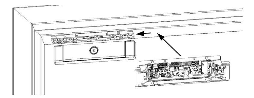
Figure 25. Assembling the Magnalock to the Bracket
- 3. SLIDE the lock forward or backward so that the entire face makes contact with the strike plate.
- 4. MARK back edge of mounting bracket at each end, and REMOVE the Magnalock from the bracket (see Figure 26, "Marking the Back Edge of the Mounting Bracket").
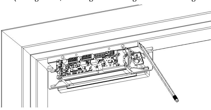
Figure 26. Marking the Back Edge of the Mounting Bracket
5. ENSURE that the mounting bracket aligns with the marks, and TIGHTEN the mounting screws (see Figure 27, "Tightening the Mounting Screws").
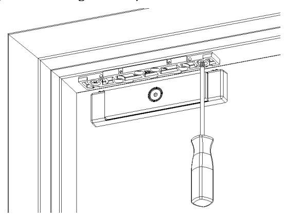
Figure 27. Tightening the Mounting Screws
6. Drill pilot holes as necessary then install and TIGHTEN the four (4) final mounting screws (see Figure 28, "Installing Final Mounting Screws"). For METAL DOORS drill 3/16" and use #12 x 1-1/2" Screws. For WOOD DOORS drill 7/32" and use #14 x 3" screws.
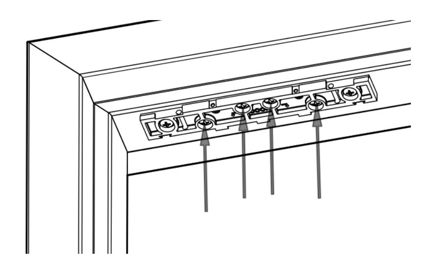
Figure 28. Installing Final Mounting Screws
7. Install the lock onto the bracket and secure in place with the two securing screws
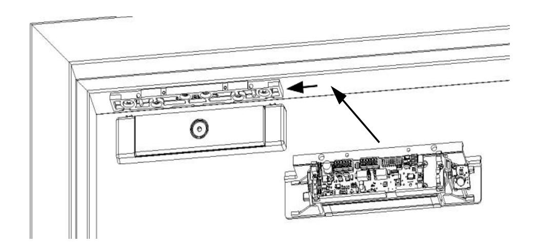
Figure 29. Install the lock on bracket
MAGNALOCK ELECTRICAL INSTALLATION
Locating and Setting the Dip Switches on the Magnalock
LOCATE and SET the dip switches (see Figure 30, "Dip Switch Location) using Table 1, "Dip Switch Selection and Position."
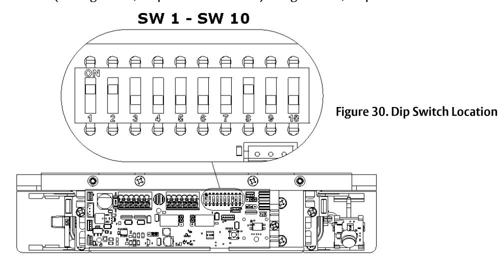
|
Component
Location |
Function Description | Selection | Position |
|---|---|---|---|
| LED Enable Switch 1 setting of the DIP switch enables or disables the | LED ENABLED | SW1 ON (default) | |
| display of the LED for lock status. | LED DISABLED | SW1 OFF | |
| LED Color Select Switch 2 of the DIP switch controls the color of the LED | SECURE = GREEN | SW 2 ON (default) | |
| when the door is secure. | SECURE = RED | SW2 OFF | |
| Auto Relock Timer Enable and Delay Selection The Auto Relock Delay Timer is disabled by default. Delay | DISABLE Delay Timer | SW3 OFF (default) | |
| can be enabled by setting the position 3 switch to ON, and | ENABLE Delay Timer | SW3 ON | |
| selecting a time delay with Position 4 and Position 5. It is recommended to enable and set the relock timer if the unit is not being used with an access control system | 5 second delay |
SW4 OFF
SW5 OFF |
|
| 10 second delay |
SW4 OFF
SW5 ON |
||
| 20 second delay |
SW4 ON
SW5 OFF |
||
| 30 second delay |
SW
4 ON
SW 5 ON |
||
| PIR Enable If the PIR functionality is no longer needed, it can be disabled. | PIR Enabled | SW8 ON (default) | |
| 8 7 8 8 10 | PIR Disabled | SW 8 OFF | |
| PIR Sensitivity The PIR sensitivity can be increased for deeps taller than 8 ft | Normal Sensitivity | SW 9 OFF (default) | |
| 8 7 8 9 10 | The PIR sensitivity can be increased for doors taller than 8 ft if needed. | High Sensitivity | SW 9 ON |
NOTE: This setting may increase the chance of non-human activation of the PIR, such as airflow around the door. It is advised to not use BondSTAT for intrusion detection systems if SW9 is ON and instead be dependent on on DPS for intrusion detection.
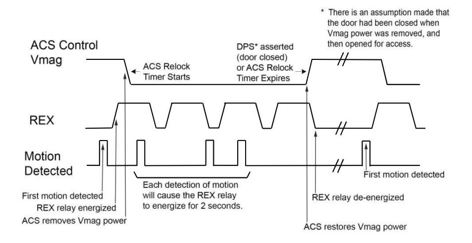
Magnalock Operation with Access Control System
NOTE: The Magnalock relock timer is recommended to be disabled when used with access control.
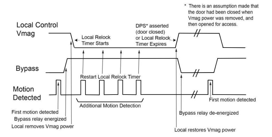
Magnalock Operation with Local Control
NOTE : The Magnalock relock timer is required to be enabled.
Locating and Setting the Jumpers on the Magnalock
1. LOCATE and SET the jumpers (see Figure 31, "Jumper Locations").
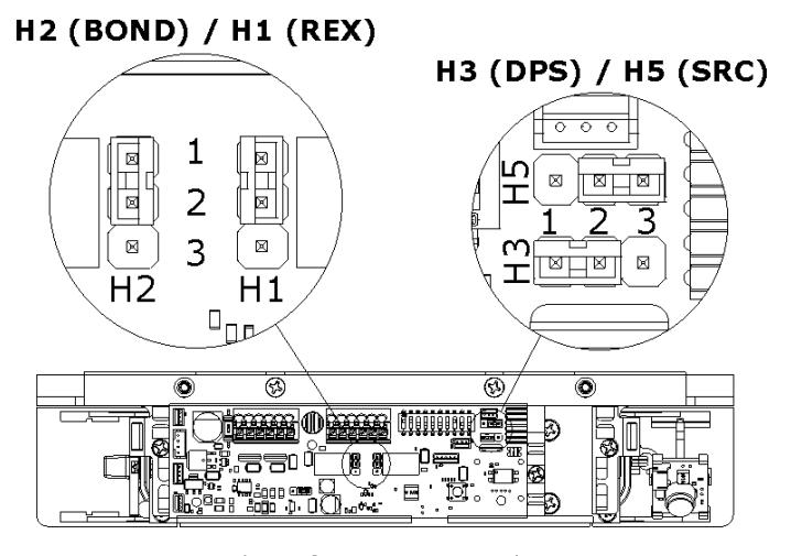
Figure 31. Jumper Locations
| Jumper | Description | Position | Illustration |
|---|---|---|---|
| H1 |
Request to Exit (REX) Mode Select A 3-
pin jumper that controls the output setting for the REX signal. |
(NC) Normally Closed Circuit
Closed, Circuit opens when REX active (default setting) |
1
2 3 |
| NOTE: Applies only to M380EBDX models. |
(NO) Normally Open Circuit
Open, Circuit closes when REX active |
1
2 3 |
|
| H2 | BondSTAT Mode Select A 3-pin jumper that controls the output setting for the BondSTAT signal. |
(NC) Normally Closed
Circuit Opens when Bond is secure (default setting) |
1
2 3 |
|
(NO) Normally Open
Circuit Closes when Bond is secure |
1
2 3 |
||
| H3 | Door Position Mode Select A 3-pin jumper that controls the output setting for the Door Position Switch (DPS) signal. |
(NC) Normally Closed
Circuit closed when Door is open (default setting) |
123 |
|
(NO) Normally Open
Circuit open when Door is open |
123 | ||
| H5 | Syncronous Release Control Mode Select A 3-pin jumper that controls lock release |
For Dual Doors with influence from Access
Control System |
123 |
|
behavior for the Syncronous Release
Control (SRC) signal when two Magnalocks are to be operated together in a double door configuration. |
For Dual Doors isolated from Access Control System (default setting) | 123 |
Documenting the Configuration Settings
1. INDICATE (circle/mark) the settings onto the adhesive-backed circuit board settings label (see Figure 32 Settings").
Dip Switch 1 - LED Enable ....................................
Figure 32. Settings
NOTE 1: The figure above shows the default settings. Settings may vary based on checklist.
NOTE 2: The settings information is required if the Magnalock needs to be inspected, serviced, or replaced.
NOTE 3: The customer/installer can write on the label, as required.
2. COMPLETE the label and AFFIX it to the inside cover of the Magnalock (see Figure 33, "Settings Label").
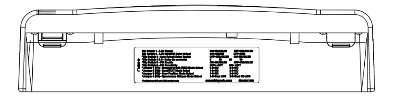
Figure 33. Settings Label
Pulling the Wiring
NOTE 1: End user and installer must comply with Fire and Building code.
NOTE 2: Models containing a REX require two separate 12 VDC/ 24 VDC wire pairs. AUX power must be continuously provided for proper operation.
1. PULL wires/cables through the wire feed-through hole(s) that are drilled in the frame.
Connecting the Final Wiring
1. CONNECT wiring using Figures 34 – 36 as guides and as applicable.
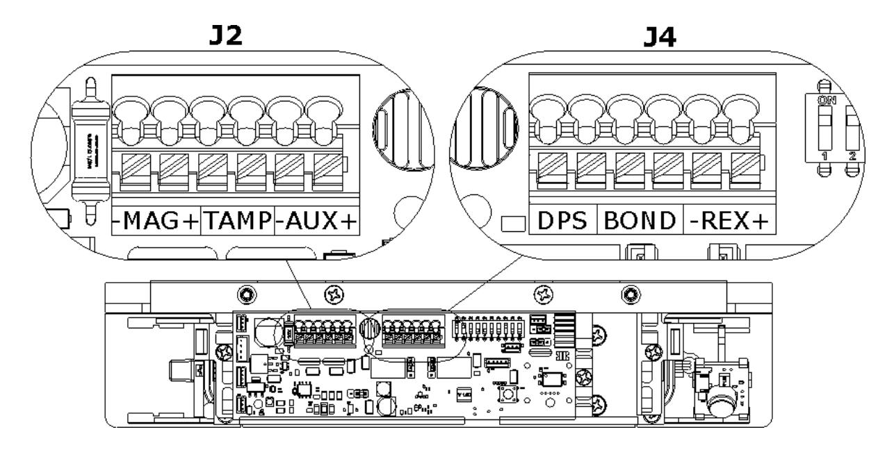
Figure 34. Location of J2 and J4 Terminals
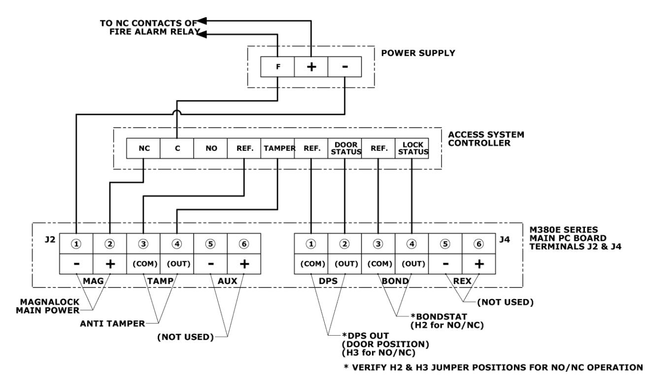
Figure 35. M380EBD Wiring Schematic (Door Position and BondSTAT only on EBD variant)
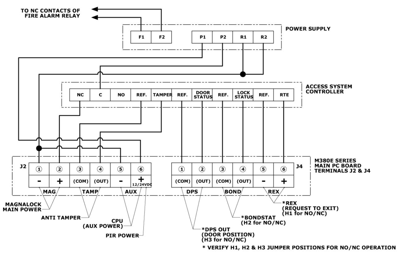
Figure 36. M380EBDX Wiring Schematic (Door Position, BondSTAT and Request to Exit)
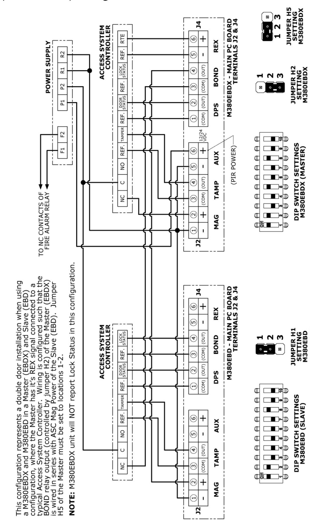
Figure 37. M380EBD and M380EBDX Dual Lock Wiring Schematic
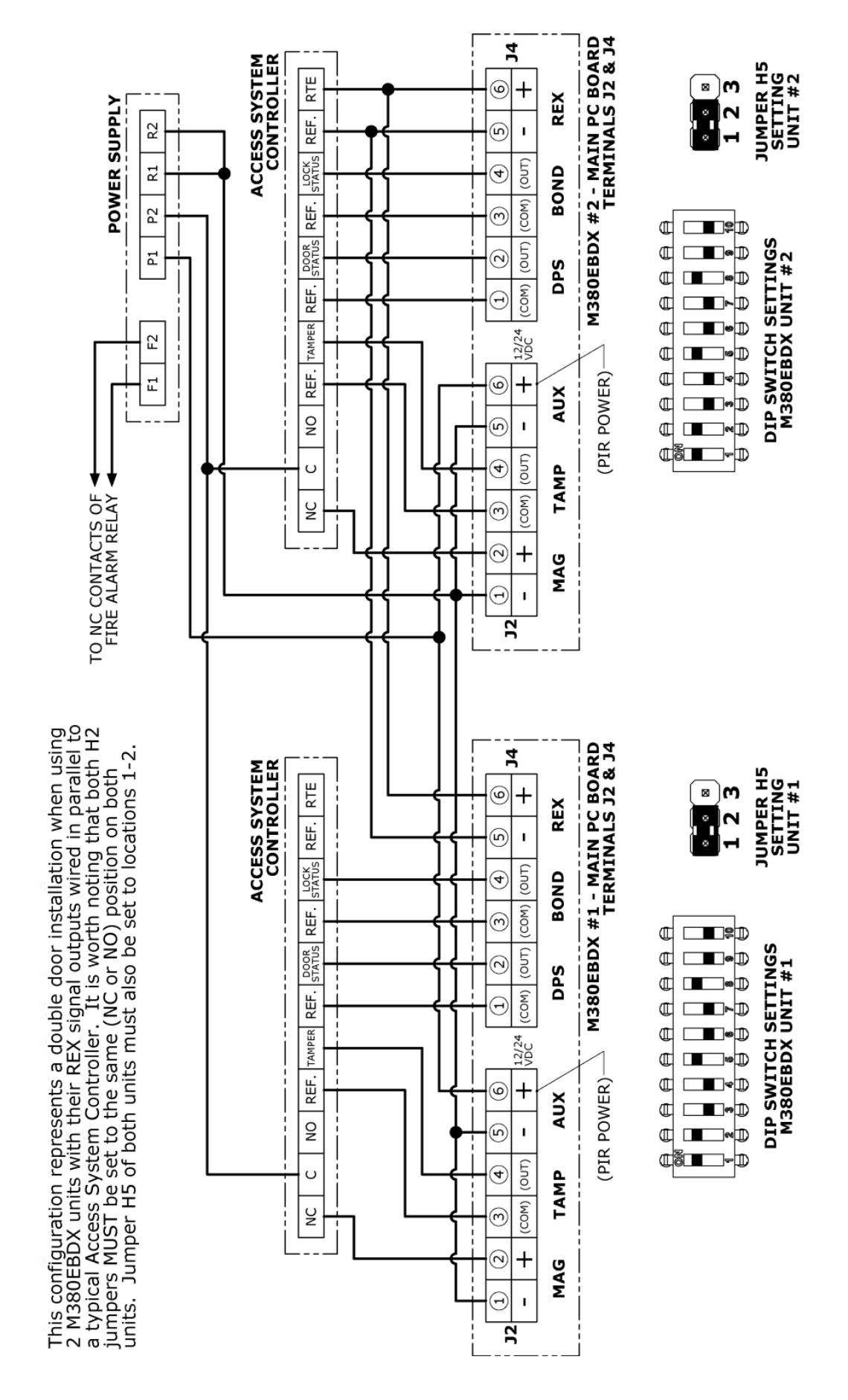
Figure 38. Dual M380EBDX Lock Wiring Schematic
Performing Initial Calibration
- NOTE 1: If calibration does not proceed according to the instruction below, please see the troubleshooting section at the end of the manual.
- NOTE 2: Initial calibration can be performed for installations in facilities that do not yet have commercial power available by using a 12V battery.
- NOTE 3: During Calibration PIR will be put in a reset mode and will be reactivated when calibration complete (applies only to models with "X" in the part number).
- NOTE 4: Access Control Systems will register DPS and/or BOND error conditions during calibration sequence.
- TECH TIP: When an installation is being performed on a door without a currently installed door handle, a pull handle can be made from masking or other tape to pull the door closed for calibration.
- 1. M380EBD and EBDX models will perform an automatic calibration when the unit is initially powered up. This process will only proceed if the door is closed and the unit has received acceptable signals from the DPS and Bond sensors. If the LED continues to flash Amber after the unit is powered and the door is closed, a manual calibration will be required. Go to step 2 in this case.
-
2. PERFORM Initial manual calibration immediately following installation if necessary.
- a. ENSURE door is closed.
- b. APPLY power to the Magnalock.
- c. VERIFY a slow one-second flash AMBER LED is occurring.
- d. PRESS and HOLD the calibration button (see Figure 39, "Location of Calibration Button").
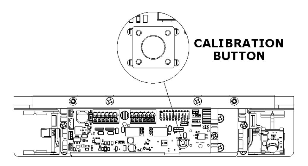
Figure 39. Location of Calibration Button
- e. VERIFY the LED changes from RED to AMBER to GREEN.
- f. WHEN the GREEN LED from the pattern above is observed, THEN RELEASE the calibration button.
- g. VERIFY the LED goes to and remains in the preset color set for secure mode, GREEN or RED.
Verifying PIR Coverage and Adjusting the PIR Coverage, as Needed
NOTE 1: ENSURE the Magnalock cover is in place when validating PIR coverage range.
1. VERIFY PIR coverage and ADJUST PIR coverage as desired (see Figure 40 and 41, "PIR Coverage" and Figure 42, "Changing the Fresnel Lens Orientation").
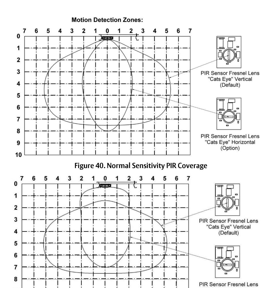
Figure 41. High Sensitivity PIR Coverage
10
"Cats Eye" Horizontal (Option)
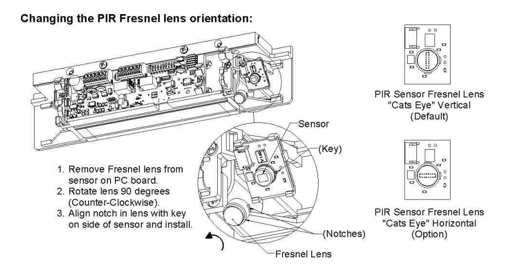
Figure 42. Changing the Fresnel Lens Orientation
2. IF PIR coverage needs to be changed, THEN ADJUST shutter to desired opening (see Figure 43, "Adjusting the PIR Shutter").
NOTE: The factory setting for the shutter is fully open, however it is possible for the shutter to close during shipment.
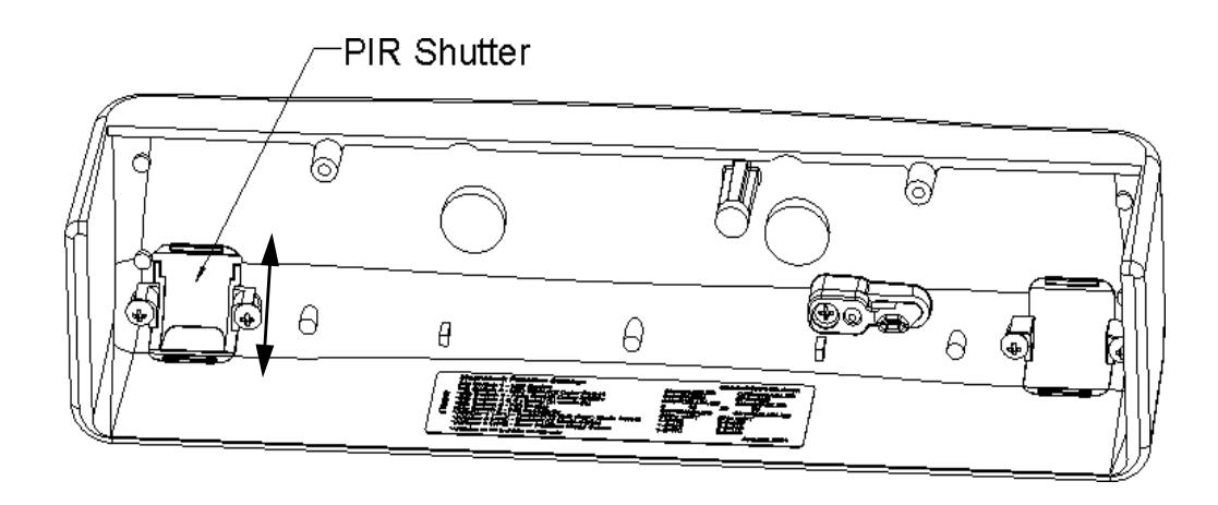
Figure 43. PIR Shutter
Re-Installing the Lock Cover
1. After calibration is complete and PIR is verified and adjusted (if necessary), RE-INSTALL the lock cover over the lock chassis and SECURE using the two (2) phillips screws (see Figure 44, "Installing the Lock Cover").
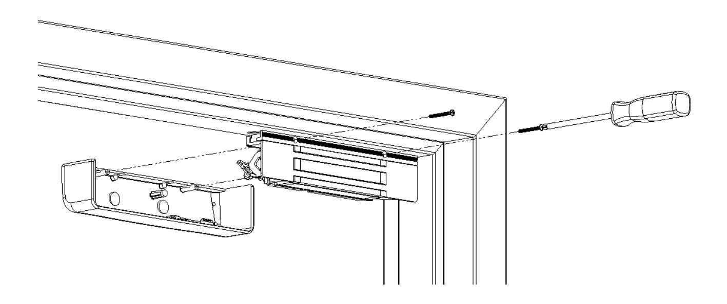
Figure 44. Installing the Lock Cover
| Possible Cause | Possible Action |
|---|---|
| Unit is awaiting calibration | If calibration button does not respond, see "Returning the Magnalock to Factory Default Settings" below. |
| Failure* of both Bond Sensors | Ensure Bond Sensor connectors are well seated. |
| Failure* of DPS Sensor | Ensure DPS Sensor connector is well seated. |
| Door is Open | Close door. |
| Vmag < 8.5 VDC | Increase voltage to Vmag, check your power supply. |
| Vaux<9 VDC (EBDX only) | Increase voltage to Vaux, check your power supply. |
| DPS Magnet missing from strike tray | Check strike tray for damage, replace if needed. |
| Failure* of DPS Sensor | Ensure DPS Sensor connector is well seated. |
| Failure* of 1 Bond Sensor | Ensure Bond Sensor connectors are well seated. |
| Door Sag | Recalibration Required. |
| Dirty Strike/Magnet Face |
Check for obstructions between strike and magnet.
Clean face of strike and magnet. |
| Vmag < 10.8 VDC | Increase voltage to Vmag, check your power supply. |
| DPS Magnet missing from strike tray | Check strike tray for damage, replace if needed. |
| Strike tray installed upside down | Ensure the strike tray is mounted with alignment tabs facing up. |
| Unit is returning to factory defaults | Ensure Dip Switch 10 is in the off position. |
| Unit is uncalibrated and missing all 3 sensor signals | Check seating of sensor connections. Contact Technical Support. |
| Door is Open | Close the door to enable calibration (flashing amber LED). |
| LED disabled by dip switch 1 | Turn SW1 to the ON position. |
| Vmag < 5 VDC (E/EBD) | Increase voltage to Vmag, check your power supply. |
| Vaux < 5 VDC (EBDX only) | Increase voltage to Vaux, check your power supply. |
| Unit is awaiting calibration Failure* of both Bond Sensors Failure* of DPS Sensor Door is Open Vmag < 8.5 VDC Vaux< 9 VDC (EBDX only) DPS Magnet missing from strike tray Failure* of DPS Sensor Failure* of 1 Bond Sensor Door Sag Dirty Strike/Magnet Face Vmag < 10.8 VDC DPS Magnet missing from strike tray Strike tray installed upside down Unit is returning to factory defaults Unit is uncalibrated and missing all 3 sensor signals Door is Open LED disabled by dip switch 1 Vmag < 5 VDC (E/EBD) |
1.
- 2.
- 3.
- 4.
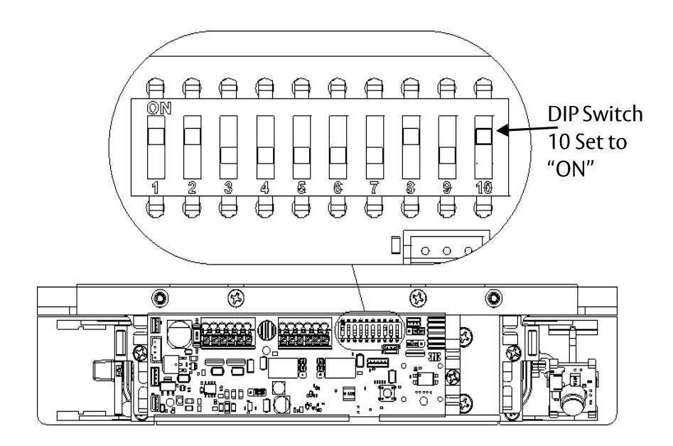
Figure 45. Setting Dip Switch 10 to ON
NOTE: When power is applied, the EEPROM contents containing previous calibration settings will be zeroed out, and the LED indicator will flash RED and then remain flashing RED until Switch 10 is moved to the "OFF" position.
- 5. APPLY Power and ENSURE LED indicator flashes RED and then remains flashing.
- 6. SET Dip Switch 10 to "OFF" (see Figure 46, "Setting Dip Switch 10 to OFF).
NOTE: After Switch 10 has been set to OFF, the LED will indicate door unsecure, and the unit will wait for the conditions necessary for Calibration, i.e., DPS is in a closed door state and BOND is achieved. Calibration will then be required .
7. CALIBRATE, as required (see Page 26, "Performing Initial Calibration").
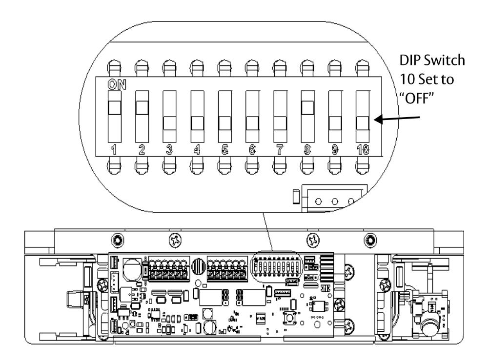
Figure 46. Setting Dip Switch 10 to OFF
WARRANTY
The Securitron M380E Series EcoMag Magnalocks are covered by the MagnaCare® lifetime replacement, no fault warranty. No registration is required. Product will be replaced forever, for any reason, including but not limited to installation error, vandalism, or act of God. Replacement product is shipped at ASSA ABLOY ESH's expense next day air if needed.
For more information, visit assaabloyesh.com