Securitron EPT-SC, EL-EPT-SC Power Transfer Installation Instructions
Open the original PDF document
View PDFStandard Wiring
1 Pass the cable from the exit device being installed through the hole in the door edge.
Given the movement of the electrical power transfer during door movement, certain steps must be taken to prevent wire breakage of 'installer provided' cabling.
Use only highly flexible cable with a robust flexible jacket. Flexible cabling is characterized by a high copper strand count (we recommend at least 19 strands) while a robust flexible jacket is at least 1/32" thick (with a maximum jacket OD of 0.275") made of PVC, PTFE, polyolefin or similar jacket material.
Provide for some wire slack for the wire entering and exiting the EPT. The wire bundle must be free to move (approximately 1") within the EPT during normal door movement to prevent wire breakage. As such, any splices or connectors should be at least 2" away from the exit of the power transfer device to ensure the wire is not restricted from moving within the EPT during normal door movement. Although using the above recommendations reduces the risk of wire breakage, ASSA ABLOY cannot be held responsible for wire failure in power transfer devices in which ASSA ABLOY did not provide the wiring.
- 2 Insert the cable through the obround hole in the lead cover, feed through the flexible shield and then out the obround hole of the other lead cover. Make necessary electrical connections at the appropriate door or frame location.
- 3 Mount the flexible shield to the lead covers as described in Diagram 4 .
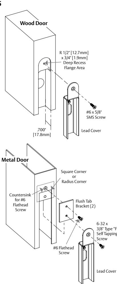
- 4 Mount the lead covers as described in Diagram 5 .
ElectroLynx® Wiring
- 1 Attach all proper connections of the harness at the door location.
- 2 Push the cable and connectors back into the hole of the door.
- 3 Mount the Flexible Shield to the Lead Cover as shown in Diagram 4 .
- 4 Mount the Lead Cover as described in Diagram 5 .
- 5 Attach the proper connections at the frame location.
- 6 Push the cable and connectors back into the frame.
- 7 Mount the Flexible Shield to the frame as shown in Diagram 4 .
EPT-SC & EL-EPT-SC Special UL/Electrical Notes
To maintain compliance with UL listings (UL 10C and UBC 7-2-1997), the maximum number of electrical conductors to be used is twelve (12) — using No. 20-22 AWG size wire.
Electrical rating for the EPT-SC and the EL-EPT-SC is 1Amp at 12V or 24V – AC or DC.
Phillips Pan Head 4X 8-32 x 3/16" Phillips Pan Head 4X Split Helical Washer
Diagram 5
Diagram 4
ELECTRONIC SECURITY HARDWARE HES | Securitron techsupport.esh@assaabloy.com | assaabloyesh.com 800 626 7590 | 10027 S. 51st Street Phoenix, AZ 85044 USA
Patent pending and/or patent www.assaabloydss.com/patents Copyright © 2019, Hanchett Entry Systems, Inc., an ASSA ABLOY Group company. All rights reserved. Reproduction in whole or in part without the express written permission of Hanchett Entry Systems, Inc. is prohibited.
Securitron® EPT-SC Electrical Power Transfer for Swing Clear Hinged Door Application Installation Instructions
ASSA ABLOY
Experience a safer and more open world
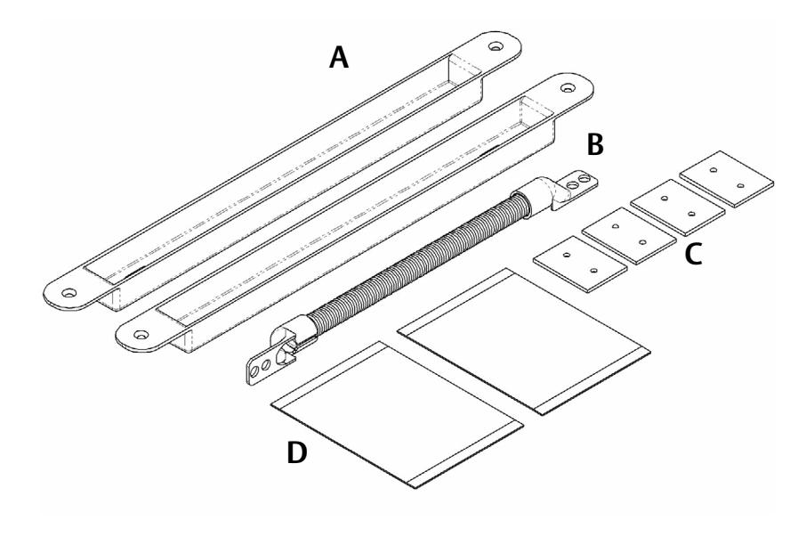
Product Components
- A EPT-SC Lead Cover (x2)
- B Flexible Shield
- C Flush Tab Bracket (x4)
- D Hardware Pack (x2)
- E Phillips Flat Head #6 X 5/8" Type "A" (x8)
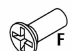
- F Phillips Flat Head 6-32 3/8" Type "F" (x8)
- G Phillips Pan Head 8-32 X 3/16" (x4)
- H Split Helical Washer for #8 Screw (x4)
Upon unpacking this product, an inventory should be made to ensure that all of the required components have been included. With these instructions and the installation template.
Recommended Tools
- Router or Saber Saw
- Measuring Instrument (Ruler/Tape Measure)
- Hammer
- Masking Tape
- Chisel
- Fish Tape or Lead Wire
- Center Punch
- Wire Strippers/Cutter
- Power Drill
- Crimp Wire Connectors
- 1/8", 5/32" and 3/4" Drill Bits
- Crimp Tool
- 3/8" Diameter X 82° Countersink Bit
- Multimeter
- Phillips and Standard Screwdrivers
Diagram 1 Product Components



Description
The EPT-SC allows an electric lock or exit device, such as a Securitron Touch Sense Bar or Touch Sense Handle, to be installed while concealing and protecting the cabling between the hinged edge of a door and its door frame. The EPT-SC provides a flexible steel shield conduit, which is approximately 5/16" [7.9mm] I.D. (inside diameter). The EL-EPT-SC is furnished with a wire harness already installed, which includes ElectroLynx® connectors at each end.
The EPT-SC power transfer device has been specifically designed and configured for installation on doors using Swing Clear type hinges.
NOTE: The EPT-SC will NOT work on doors utilizing center pivot type hinges
Installation
For a proper EPT-SC install, all doors and frames must utilize a flush surface mount installation. If the door/frame is pre-prepped by the manufacturer, then use the pre-fabricated mounting features and the hardware provided to install the EPT-SC as discussed in Diagram 2 or 3 . If the installation is a field retrofit, determine the door and frame construction, then proceed to mark the door and frame in accordance with Diagram 2 or 3 .
4 of 4 1 of 4
Vertical Placement
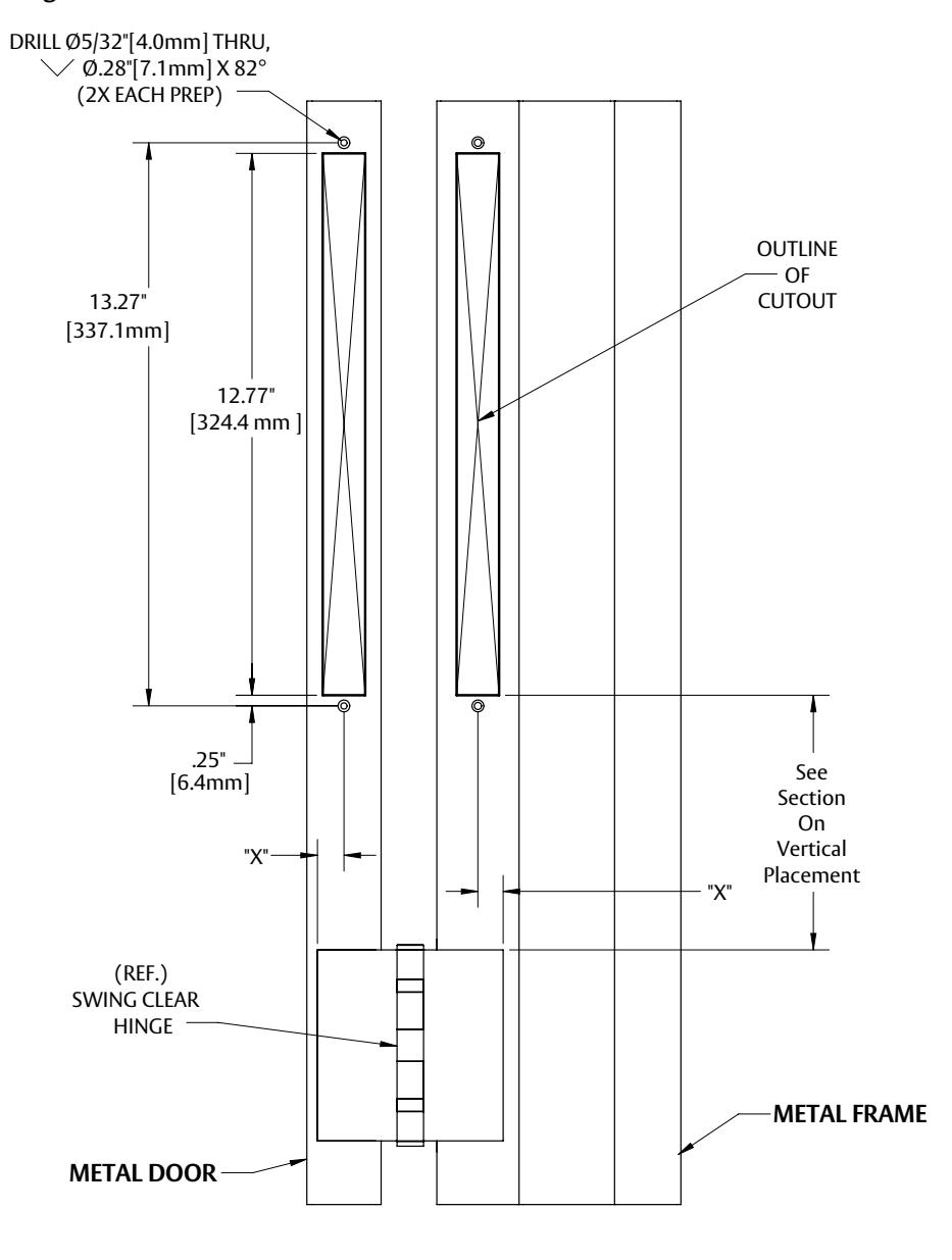
Because of potential structural obstacles within metal doors and frames, the EPT-SC lead covers should be positioned a minimum of 6" [152.4mm] from any hinge recess (as shown in Diagram 2 ) or centered between hinges.
NOTE: Due to variances in manufacturing, the door/ frame manufacturer should be consulted for specific construction and configuration information.
Marking the Door & Frame for Install
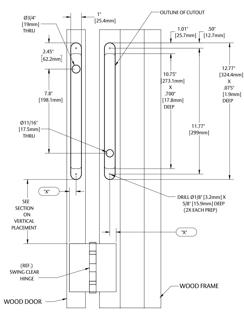
- Mark a vertical centerline for the EPT-SC lead cover at the center of the door edge. Measure the distance from this mark to the edge of the hinge half that is attached to the door (see "X" of "DOOR" prep. in Diagram 2 or 3). Use this same distance to mark from the edge of the hinge half on the frame (see "X" of "FRAME" prep. In Diagram 2 or 3).
- 2 Using the included template and the information shown in Diagram 3 (for wood) or Diagram 2 (for metal), align and mark the cutout positions required for the lead covers on both the door edge and the frame. NOTE: Because of the nature of the Swing Clear hinges and the orientation of the edge of the door in the open position, the door will most likely need to be removed after marking to perform the preparation process for the lead cover installation.
Metal Doors & Frames
- 1 Using a router or saw, create the cutout required for the lead cover. The cutout may be cut with a radius (as shown) or square-cornered as noted in Diagram 2.
- 2 Mark, drill and countersink the two (2) 5/32" [4mm] diameter flush tab bracket mounting holes at each end of the cutout as shown and directed on the template.
- 3 Insert and install the two (2) flush tab brackets provided using the included 6-32 x 3/8" type "F" (self-tapping) screws.
NOTE: At this point, if the door was removed, it may be reinstalled.
Diagram 2
Wood Doors & Frames
- 1 Using a router with a 1/4" diameter bit, cut the main recess slot into the edge of the door and the frame to a depth of .700" [17.8mm] as shown in Diagram 3 .
- 2 Using a 1" [25.4mm] diameter bit with the router depth set to .075" [1.9mm], cut the two (2) recessed flange areas for the flush mount tabs.
- One at a time, place each lead cover into position and mark the two (2) mounting hole locations and the cable feed thru (obround) hole location for each cover. NOTE: The holes required for the wire feed thru in the door and frame must be positioned at opposing ends to each other. (i.e. if the hole is toward the top of the lead cover for the door, then the hole for the lead cover in the frame should be at the bottom, see Diagram 3.)
- 4 Drill the (2) two mounting holes for each lead cover using a 1/8" [3.2mm] diameter drill bit to a depth of approximately 5/8" [15.9mm].
- 5 Drill a 3/4" [19.0mm] diameter hole into the door to provide routing of the wires to the device being used. Then drill a 11/16" [17.5mm] diameter hole through the frame at the marked locations. NOTE: At this point, if the door was removed, it may be reinstalled.
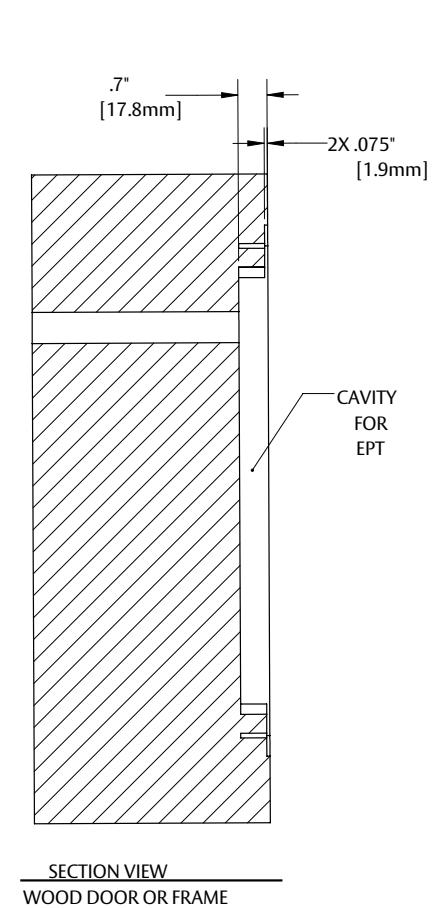
Diagram 3
2 of 4 3 of 4