Securitron DR100 Installation Instructions
Open the original PDF document
View PDFDR100 Aperio® Wireless Card Reader with Relay (BASIC MODE)
Installation & Operating Instructions
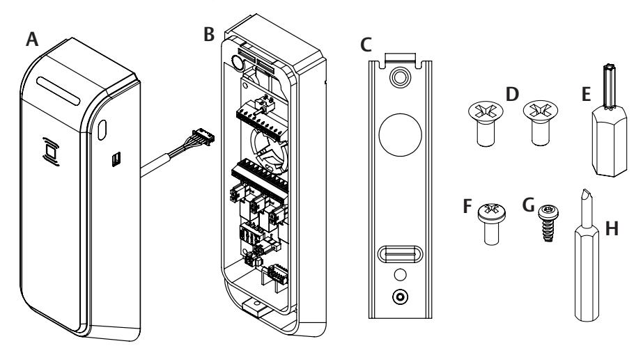
Product Components Standard Installation
- A Reader
- B Relay Housing
- C Mounting Bracket
- D (2X) 6-32 x 1/2" Type F Self Tapping Screws
- E T8 Security Torx Bit
- F 4-40 Pan Head Screw
- G 4-40 Security Torx Screw
- H 2mm Slotted Bit
Diagram 1 Product Components Standard
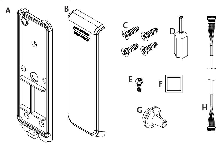
Product Contents Secure Installation Kit
- A Reader Backplate
- B Secure Side Relay Cover
- C (4X) 4-20 Self Tapping screw
- D T8 Security Torx Bit
- E 4-40 Security Torx Screw
- F Alcohol Swab
- G Wire Sealing Grommet
- H Wire Harness Extender
Diagram 2 Product Components Secure Kit
Product Specs
| Parameter | Values | |
|---|---|---|
| Power Supply | 12 – 24 VDC | |
| Operating Temperature | 14˚ to 151˚ F [-10˚ to 66˚ C] | |
|
Cold Weather Pack
Operating Temperature* |
-40˚ to 151˚ F [-40˚ to 66˚ C] | |
| Storage Temperature | -40˚ to 185˚ F [-40˚ to 85˚ C] | |
|
Max Operating
Relative Humidity |
93 % RH at 89˚ F | |
| IP Class | IP65 | |
| Network | IEEE 802.15.4 (e.g. Aperio) 2.4 GHz | |
| BLE | Bluetooth 4.0 | |
| Max Operating Current Draw | 57.4 mA | |
|
Max Current Draw with
Heater Activated* |
123 mA at 12 V | 245 mA at 24 V | |
| Inputs | |||||
|---|---|---|---|---|---|
| 2 DPS, Digital input** | |||||
| 1 REX, Digital input | Close / Open Externally Accessible | ||||
| 1 DX (Deadbolt Switch) |
REX, DX, and Privacy are not functional
at release. (Release date TBD) |
||||
| 1 Privacy | |||||
| Outputs | |||||
| # of Relays | 3 | ||||
|
Relay Switching
Capacity, Max |
2A per Relay*** | ||||
| 1 Tamper | Relay Housing Side | ||||
| 2 Tamper | Reader Side | ||||
* Requires extreme cold temperature hardware pack.
** 2 DPS can be used with device however only one DPS signal will be sent to EAC.
***6 A max operating current draw total for product when all relays are in the wetted configuration and fully loaded.
Mounting the Relay Housing
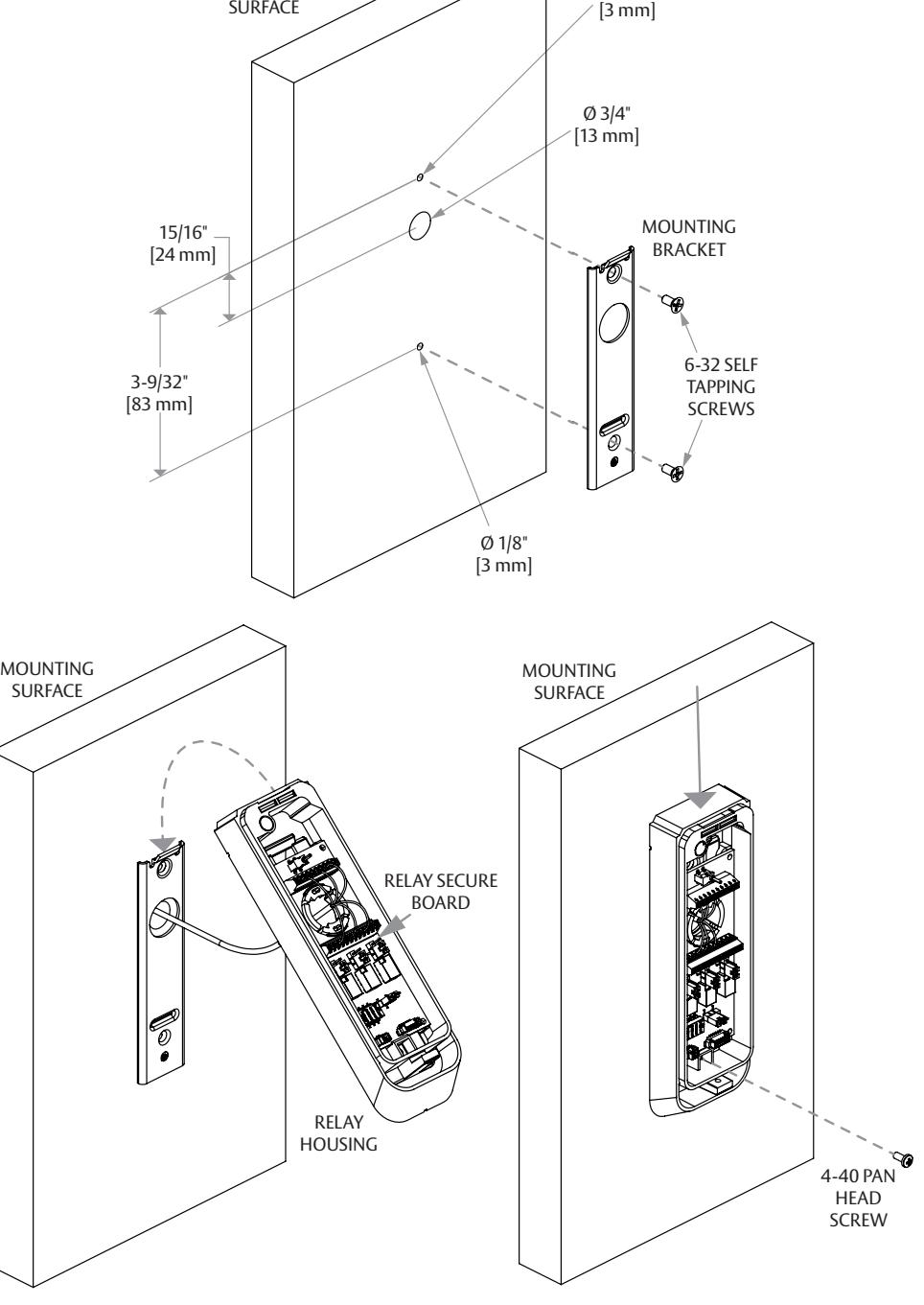
- 1 DRILL 3/4" hole in location shown for wires to pass through.
- 2 USE Mounting bracket as template to drill 2 x 1/8" holes as shown for a 6-32 self tapping screw. Ensure Mounting Bracket is level and aligned to the 3/4" hole before drilling 1/8" holes.
- 3 INSTALL mounting bracket using 2x 6-32 self tapping screws.
- 4 WIRE input/output wires into Relay Secure Board (details in next section).

Do not proceed with Relay Housing mounting until wiring is complete.
- 5 HOOK Relay Housing onto mounting bracket and rotate until Relay Housing is fully seated onto bracket and Relay Housing Gasket is fully seated against mounting surface. Downward pressure may be needed in order to compress gasket and fully seat Relay Housing to Bracket.
- 6 INSTALL provided 4-40 Pan Head Screw to secure Relay Housing to bracket.
NOTE: In the standard configuration the Relay Housing is to be mounted on the unsecure side of the door. If the Secure Side Installation Kit is being used, the Relay Housing is to be mounted on the Secure side of the door.
Ø 1/8"
Wiring the DR100 – I/O's
J1*
| Terminal# | Name | Type | Voltage Level | ||
|---|---|---|---|---|---|
| 1 | V EXT | Input | 12 – 24 VDC | ||
| 2 | RELAY COM 1 | Output | 12 – 24 VAC/VDC** | ||
| 3 | RELAY NO 1 | Output | 12 – 24 VAC/VDC** | ||
| 4 | RELAY NC 1 | Output | 12 – 24 VAC/VDC** | ||
| 5 | RELAY COM 2 | Output | 12 – 24 VAC/VDC** | ||
| 6 | RELAY NO 2 | Output | 12 – 24 VAC/VDC** | ||
| 7 | RELAY NC 2 | Output | 12 – 24 VAC/VDC** | ||
| 8 | RELAY COM 3 | Output | 12 – 24 VAC/VDC** | ||
| 9 | RELAY NO 3 | Output | 12 – 24 VAC/VDC** | ||
| 10 | RELAY NC 3 | Output | 12 – 24 VAC/VDC** | ||
| 11 | GND | Input | Power Ground / Return | ||
| 12 | GND | Input | Power Ground / Return | *Terminal blocks accept 18 – 30 AWG wire. |
J2*
Diagram 3 Mounting
MOUNTING
| Terminal# | Name | Type | Voltage Level |
|---|---|---|---|
| 1 | PRIVACY NO*** | Not Used — Do Not Connect | |
| 2 | PRIVACY COM*** | Not Used — Do Not Connect | |
| 3 | DX NO*** | Not Used — Do Not Connect | |
| 4 | DX COM*** | Not Used — Do Not Connect | |
| 5 | REX NO*** | Not Used — Do Not Connect | |
| 6 | REX COM*** | Not Used — Do Not Connect | |
| 7 | DPS 2 NO | Input | 3.3 VDC |
| 8 | DPS 2 COM | Input | 3.3 VDC |
| 9 | DPS 1 NO | Input | 3.3 VDC |
| 10 | DPS 1 COM | Input | 3.3 VDC |
**12-24 VAC is only applicabe when relays are set to the dry configuration.
*** Privacy, DX, and Rex to become functional at later date.
Wiring the DR100 – Terminal Blocks
]1 Output/Power Terminals
- 1 12-24 VDC
- 2 Relay COM 1
- 3 Relay NO 1
- 4 Relay NC 1
- 5 Relay COM 2
- 6 Relay NO 2
- 7 Relay NC 2
- 8 Relay COM 3
- 9 Relay NO 3
- 10 Relay NC 3
- 11 GND
- 12 GND
Make wire connections at the appropriate wire terminal with Relay Secure Board seated in housing. Removal of the Relay Secure Board from housing is not recommended.
Wet/Dry Jumper Settings
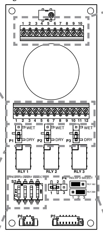
Wet/Dry jumper settings can be configured to set each individual relay to be a wet or dry contact.
- When set as a WET CONTACT, the relay will provide direct power to the device connected to the relay from the power source connected to the Relay Secure Board.
- When set as a DRY CONTACT, the relay will not provide direct power to the device. Use this setting if the device is powered externally.
- The voltage supplied to an external device through a wetted relay will be equivalent to the voltage supplied to the relay board.
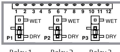
Relay 1 Relay 2 Relay 3 WET/DRY WET/DRY WET/DRY Jumper Jumper Jumper
Diagram 4
Delay Settings
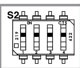
The Delay setting is used to delay the actuation between RELAY 1 and 3.
- The Delay will only apply to RELAY 3 if the RELAY 2 Select jumper is in the left position. The delay will apply to both RELAY 2 and 3 if the RELAY 2 Select jumper is in the right position.
- The delay time is configurable via the dip switch settings on the Relay Secure Board.
Dip Switches
Relay 2 Sect Jumper Delay Timing
| П 2 П | Delay only applies to RELAY 3 |
|---|---|
| П П П П П П П П П П П П П П П П П | (factory default) |
| 1 1 3 |
Delay applies to both
RELAY 2 and RELAY 3 |
J2 Input Terminals
- 1 Privacy NO (Not Used)
- 2 Privacy COM (Not Used)
- 3 DX NO (Not Used)
- 4 DX COM (Not Used)
- 5 REX NO (Not Used)
- 6 REX COM (Not Used)
- 7 DPS 2 NO**
- 8 DPS 2 COM**
- 9 DPS 1 NO**
- 10 DPS 1 COM**
**NOTE: Both DPS 1 and DPS 2 need to be closed in order for the EAC to see a DPS secure signal. The unit comes with a jumper pre-installed to close DPS 1. If using only one DPS, install into DPS 2. If using two DPS, remove the jumper in DPS 1 and install each DPS individually to DPS 1 and DPS 2. Wireless communication of DPS 1 and DPS 2 have not been evaluated to UL294.
Relay 2 Jumper Settings
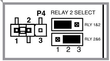
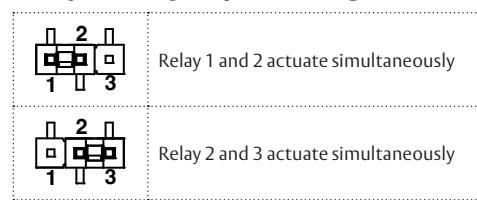
The Relay 2 will always actuate simultaneously with either Relay 1 or Relay 3.
- To configure RELAY 2 to actuate simultaneously with RELAY 1 move the jumper to left position so it is covering pins 1 and 2 (default configuration).
- To configure RELAY 2 to actuate simultaneously with RELAY 3 move the jumper to right position so it is covering pins 2 and 3.
Relay 2 Select Jumper
Relay 2 Sect Jumper Timing
Wiring the DR100 Delay Dip Switch Settings
| DR100 DIP-SWITCHES# | POSITION | SELECTION | FUNCTION DESCRIPTION | FACTORY DEFAULT | |||
|---|---|---|---|---|---|---|---|
| ON Position | SW1 | SW2 | SW3 | SW4 | DELAY (S) | ||
| ON | ON | ON | ON | 0 | |||
| OFF | ON | ON | ON | 0.5 | |||
| ON | OFF | ON | ON | 1 | |||
| OFF | OFF | ON | ON | 1.5 | |||
| ON | ON | OFF | ON | 2 | Activates a time delay | ||
| OFF | ON | OFF | ON | 2.5 |
between the actuation
of RELAY 1 and RELAY 3. RELAY 2 will also see the delay if the RELAY 2 Select Jumper is configured |
||
| ON | OFF | OFF | ON | 3 | 0 Seconds | ||
| OFF Position | OFF | OFF | OFF | ON | 3.5 | ||
| ON | ON | ON | OFF | 4 | |||
| OFF | ON | ON | OFF | 4.5 |
such that RELAY 2
actuates simultaneously |
||
| ON | OFF | ON | OFF | 5 | with RELAY 3. | ||
| OFF | OFF | ON | OFF | 5.5 | |||
| ON | ON | OFF | OFF | 10 | |||
| OFF | ON | OFF | OFF | 15 | |||
| ON | OFF | OFF | OFF | 20 | |||
| OFF | OFF | OFF | OFF | 30 | |||
Common Modes of Operation
Diagram 5 Typical door system with FAIL-SECURE electric lock.
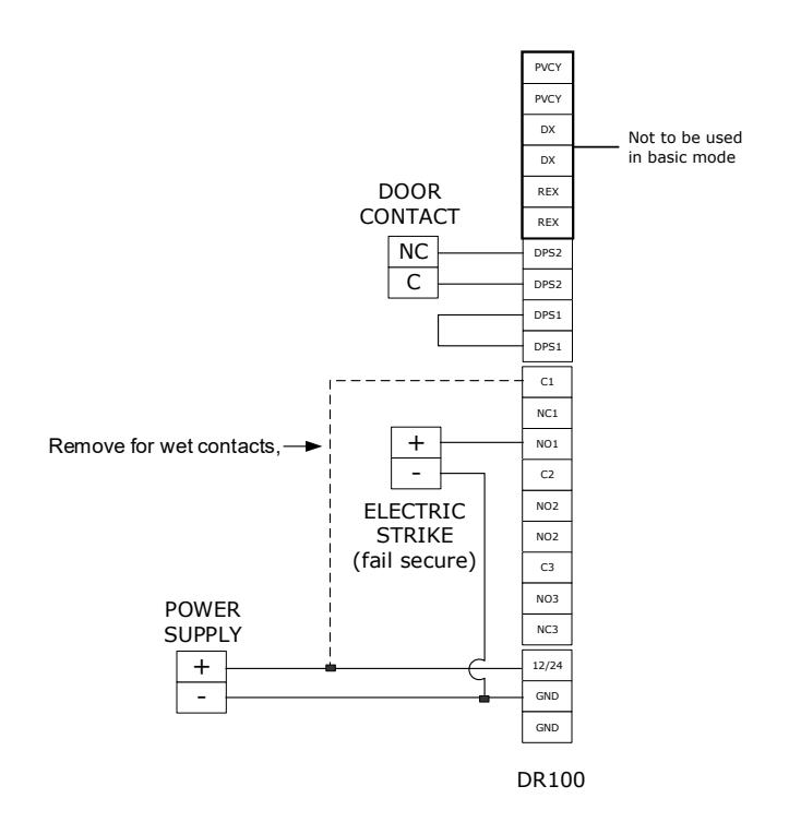
Diagram 6 Typical door system with FAIL-SAFE electric lock.
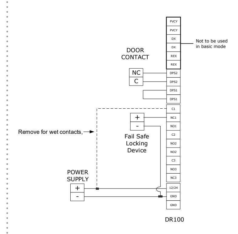
Diagram 7 Typical door system with electronically activated rollup door.
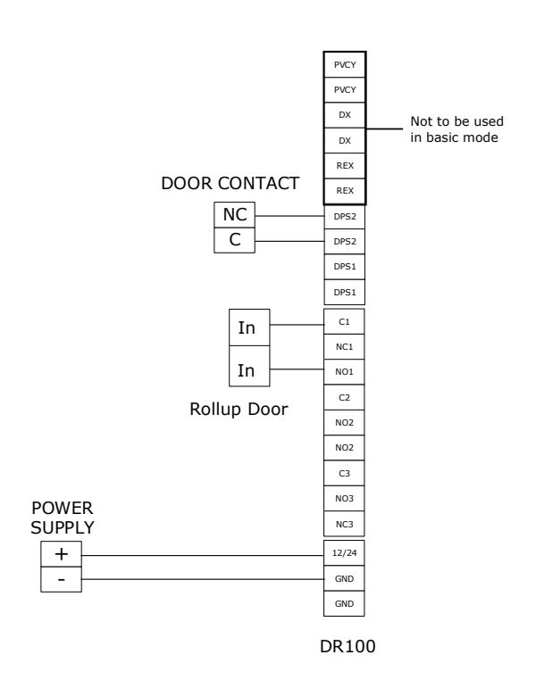
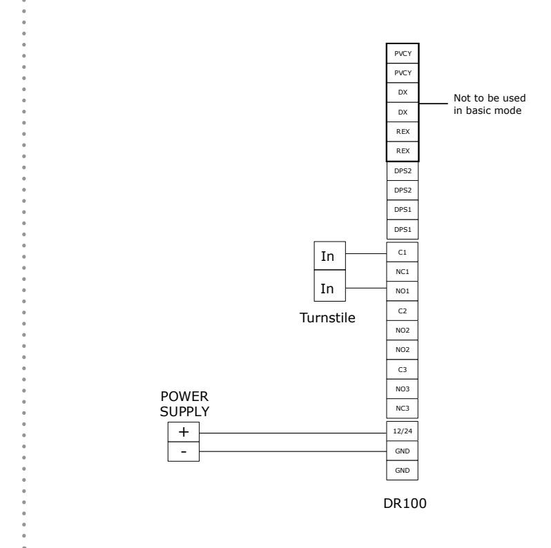
Diagram 8 Typical door system with electronically activated turnstile.
Standard Configuration Reader Installation
1 CONNECT Reader Wire Harness from the Reader to the Relay Secure Board as shown. If using the optional heater, connect this wire as well, Diagram 9.
NOTE: The Heater allows the device to function below -14˚ F [-10˚ C] and only activates below this temperature. The heater will come pre-installed on the Reader if the DR100E model is ordered. If the Heater was purchased separately, please refer to the Heater installation instructions provided in the Cold Weather Pack.
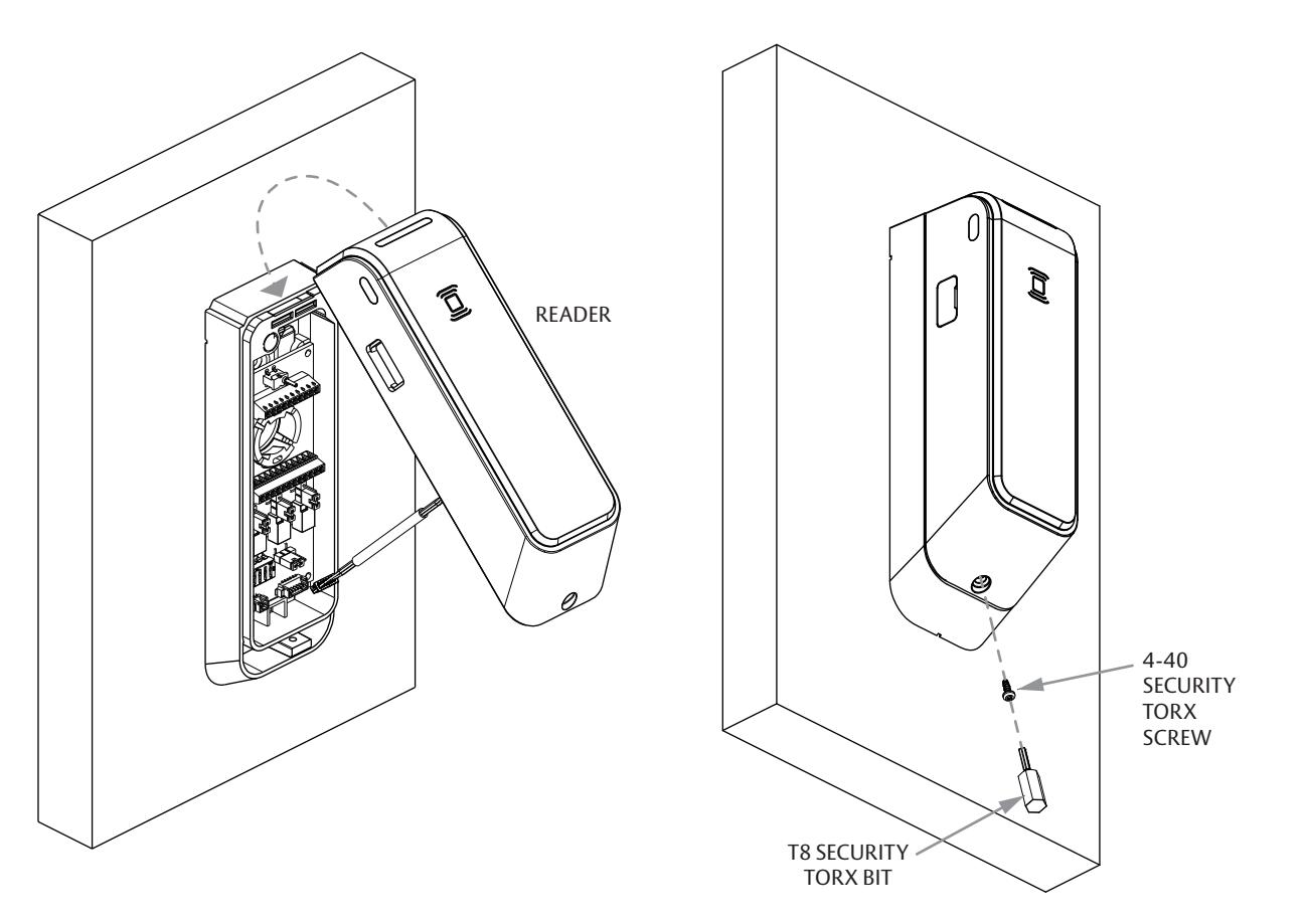
- 2 HOOK Reader onto the top of the Relay Housing and rotate closed, Diagram 10 .
- 3 INSTALL 4-40 Security Torx Screw to secure reader to Relay Housing using provided T8 Security Torx Bit.
- 4 VERIFY proper installation/wiring and ensure that all connected devices are operating as intended. Note: All steps must be complete for device to exit tamper state and for device to function properly.
Diagram 9 Connect Reader.
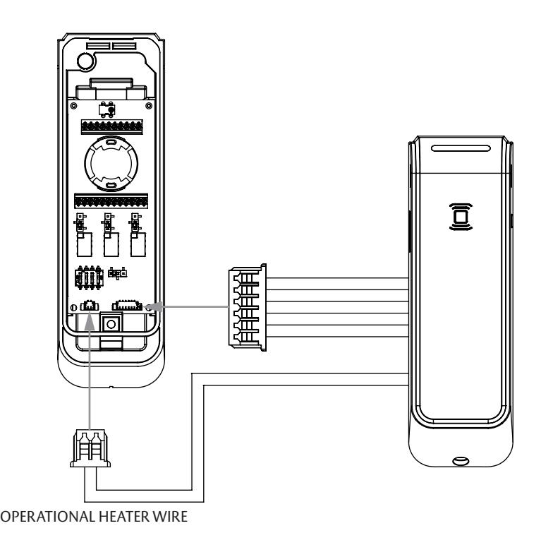
Diagram 10 Hook Reader and install Torx Screw.
Secure Installation Kit Reader Installation
Although the DR100 has several mechanisms to detect tamper situations when mounted in the standard configuration, there may be a desire to mount the Relay Housing in a secure area apart from the Reader. The secure side installation kit provides the hardware needed to mount the Relay Housing on the secure side of the opening and mount the Reader on the opposite side.
NOTE: The DR100 is designed to remain securely affixed to a smooth mounting surface using only the mounting tape installed on the Reader Backplate. Additional optional fasteners are provided if the mounting surface is rough. The optional Wire Sealing Grommet is also provided to prevent moisture intrusion when mounting on an rough surface.
-
1
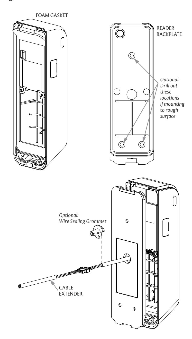
REMOVE foam gasket on back of Reader, by peeling gasket back towards the top of the reader and slowing peeling off.
- • Optional DRILL 3 x 1/8" DIA. holes in the Reader Backplate as indicated (deburr the holes after drilling).
-
2
INSERT reader cable thru exit hole on Reader Backplate.
- • Optional WRAP Wire Sealing Grommet on Reader wire harness by opening slit in grommet and pressing onto the Reader wire harness.
- 3 CONNECT Wire Harness Extender to Reader wire harness.
NOTE: Only use provided Wire Harness Extender. No other extender should be used.
Diagram 11 Reader Installation.
Mounting Reader to Surface
NOTE: When installing with the Secure Installation Kit the Reader is to be mounted on the unsecure side of the door, opposite to the Relay Housing.
-
4
DRILL 1/2" hole in mounting surface as indicated in
Diagram 12
.
- • Optional Use Reader Backplate as a template to drill 3 x 3/32" holes in mounting surface. (deburr the holes after drilling). Ensure back plate is level and aligned to 1/2" hole before drilling 3/32" holes.
- 5 CLEAN Reader mounting surface using provided alcohol swab.
- 6 ROUTE Reader wire harness and Wire Harness Extender through the 1/2" hole to the opening in the Relay Housing. This harness will go through the same opening as the input, output, and power wires. Diagram 13 .
3-11/32" [85 mm] Ø 1/2" [13 mm] Optional 3X Ø 3/32" [2 mm] 1-7/16" [37 mm]
3/4" [19 mm]
Diagram 12 Drill holes. Diagram 13 Route wires.
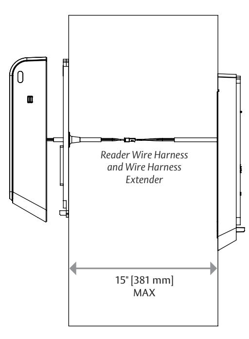
NOTE: The length allowable between reader and relay housing is 15".
Wiring Distance from reader to secure board can not be extended further than provided cables.
-
7
MOUNT Reader by removing the adhesive tape backing on Reader Backplate and adhering to desired location. Apply pressure for at least 1 minute to properly activate the adhesive tape.
Diagram 14
.
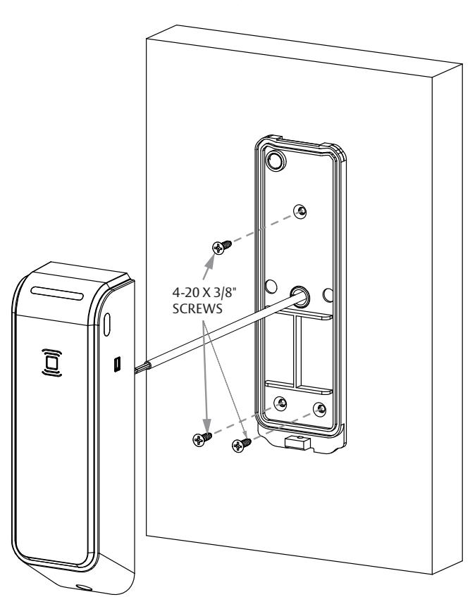
- • Optional Secure Reader Backplate to door with the provided 3 x 4-20 Self-Tapping Screws. Diagram 15 .
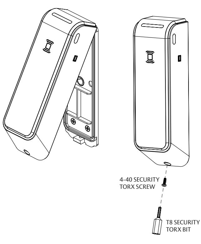
- ADHESIVE 8 HOOK Reader onto top of Reader Backplate and rotate until reader is fully seated. Diagram 16 .
- TAPE 9 SECURE reader to Reader Backplate with the provided 4-40 Security Torx Screw, fasten with T8 Security Torx Bit. Diagram 17 .
NOTE: Ensure reader is fully seated on Reader Backplate.
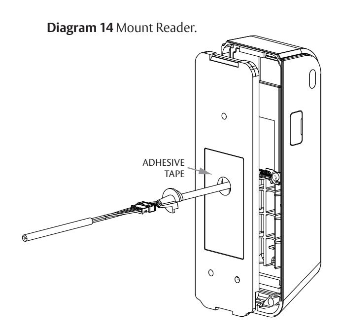
Diagram 15 Secure Reader Backplate. Diagram 16 Hook Reader. Diagram 17 Secure Reader.
Secure Side Relay Cover Installation
NOTE: The following steps are performed on the secure side of the opening.
- 1 ROUTE the Wire Harness Extender to the side of the terminal blocks as shown and tuck excess cable back into the wire opening.
- 2 CONNECT the Wire Harness Extender to location shown below on relay board. Diagram 18 .
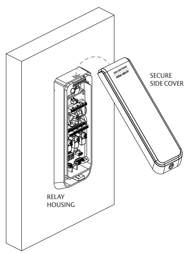
- 3 HOOK Secure Side Relay Cover onto top of Relay Housing and rotate until Secure Side Relay Cover is fully seated. Diagram 19 .
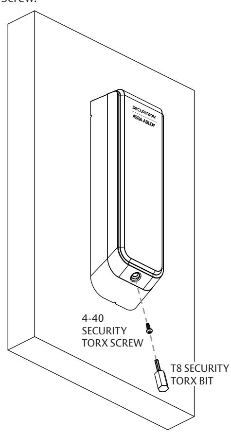
- 4 INSTALL 4-40 Security Torx Screw to secure the Secure Side Relay Cover to Relay Housing using provided T8 Security Torx Bit. Diagram 20 .
- 5 VERIFY proper installation/wiring and ensure that all connected devices are operating as intended.
NOTE: All steps must be complete for device to exit tamper state and for device to function properly.
Diagram 18 Connect Wire.
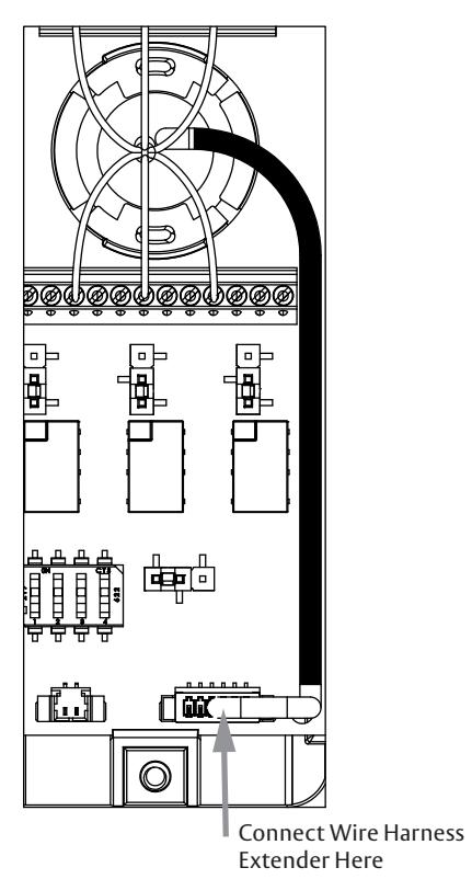
Diagram 19 Secure Side Cover. Diagram 20 Install Screw.
Aperio Hub Specifications
- Approvals ETL, FCC, IC, C-Tick
- Safety & Emissions FCC 47CFR Part 15 subpart B and subpart C; IC RSS-210 EN ETSI 301 489-17 v2.1.1; ENETSI 300 328 v1.7.1; EN 60950-1 ed.2 2007
- Dimensions 82mm x 82mm x 37mm
- Power Supply 8-24 VDC
- Current 250 mA minimum
- Internal Antenna 2 cross polarized dipoles
- External Antenna (Part No. EXT-10-ANT) One reverse polarity SMA external antenna connector. Optional antenna type dipole with max antenna gain of 3.9 dBi.
- Radio Standard IEEE 802.15.4(2.4GHz) 15 channels (11-25)
- Encryption (RadioCommunications) AES 128 bits
- Wireless Operating Range Up to 50 ft
- Receiver Sensitivity -100dBm 20% PER
- Wireless Transmit Power 10 dBm/MHz
- Class of Protection IP 20
- Operating temperature 41°F to 95°F [5°C to 35°C]
- Humidity < 95% non-condensing
- Status LED (red/green/yellow) NOTE: This bub has not been evaluated.
NOTE: This hub has not been evaluated by UL.
LED Codes
| Aperio LED LOCK Codes | |||||
|---|---|---|---|---|---|
| (1) ONE Yellow Flash | Card read | ||||
| (1) ONE Green Flash | Access Granted | ||||
| (5) FIVE Yellow (1) ONE Red | Force Closed (in open mode) | ||||
| Continuous Yellow Flashes (.25 sec every second) | 1 1 1 1 | Comhub busy | |||
| (1) ONE Red Flash |
Access Denied
(AC Online) |
||||
| (3) THREE Red Flash | III |
Access Denied
(AC Offline) |
|||
|
Continuous Red Flashes
(.125 sec every second) |
1111 | Lock is Blocked (when closing) | |||
| (10) TEN Red Flashes | Error in Lock | ||||
| Continuous Yellow Flashes (.25 sec every 5 seconds) | Low Battery | ||||
| Continuous Red Flashes (.25 sec every 5 seconds) | ı | Dead Battery | |||
| Aperio LED HUB Codes | |||||
|---|---|---|---|---|---|
| Steady Green | Online | ||||
|
Steady Green
+(1) ONE Red Flash |
Lock Offline | ||||
|
Steady Green
+(2) TWO Red Flashes |
Access Control
Offline |
||||
|
Steady Green
+(3) Three Red Flashes |
Access Control
& Lock Offline |
||||
| Flashing Yellow | UHF Communication | ||||
Connecting the Hub
The following applies only to Aperio factory paired kits with AH20 Hubs.
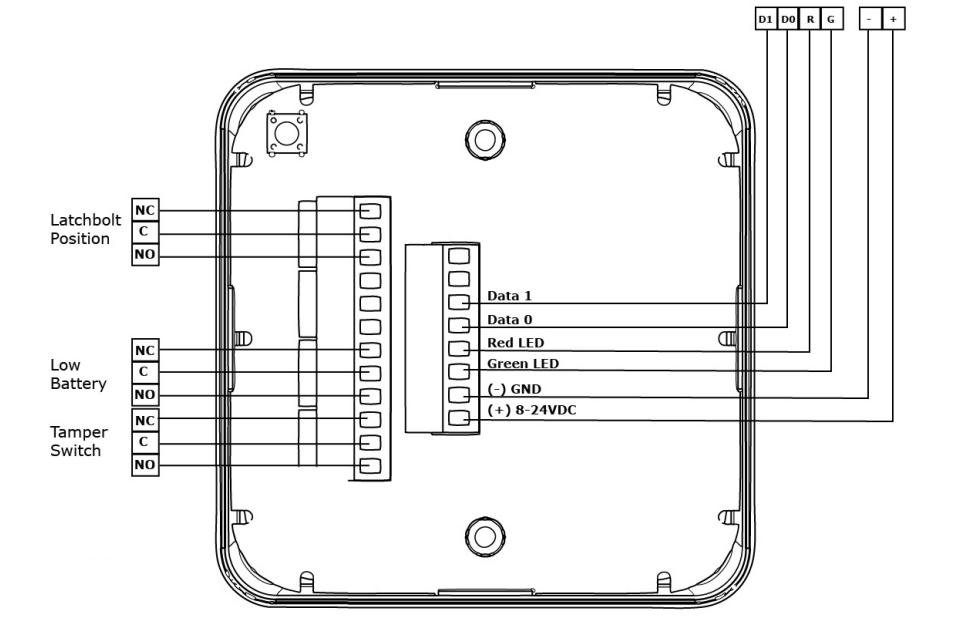
1. Connect the Wiegand D1, D0, red, and green LED signals.
NOTE: The Green LED input is used to grant access to the connected device. If the Green LED signal is not available to indicate approved access, the approval input can be activated by a relay with "NO" attached to Green LED and "C" to GND. The Red LED input is used to indicate access denied. If the RED LED signal is not connected, the reader will flash RED three times when a non-approved card is presented indicating loss of connection to the hub rather than access denied. Any other codes may be reference on the LED reference card above.
For questions regarding installation of the hubs such as hub placement, coverage area, or materials that may interfere or reduce range, please review the hub installation instructions:

Product Specifications (continued)
- • Approvals FCC, IC
- • Wireless Frequency 2.4GHz, IEEE 802.15.4, using AES 128-bit encryption
-
• HID® multiCLASS SE® technology Credentials Supported
-
• High Frequency (13.56 MHz)
- » HID iCLASS®
- » HID iCLASS SE® (SIO-enabled)
- » HID iCLASS® Seos™
- » HID MIFARE® SE
- » HID DESfire® EV1 SE
- » MIFARE CLASSIC
- » DESfire® EV1
- » DESfire® EV2 (Legacy Mode)
- • Low Frequency (125 kHz) HID Prox®, AWID, EM4102
- • Mobile Access Credentials NFC HID BLE Mobile Access SEOS iOS Apple Wallet
-
• High Frequency (13.56 MHz)
Certifications
- UL 294 listed Indoor & Outdoor Rated
- FCC Part 15 & Industry Canada Compliant
- RoHS compliant
Safety and Emissions
- • FCC 47CFR Part 15, subpart C
- • IC RSS-102
- • RSS-210
- • RSS-247
- • RE Directive 2014/53/EU EN 301 489-1, EN 301 489-3, EN 300 440, EN 300 330, EN 300 328, EN 62368-1, EN 62479
NOTE: The effective operational range/distance (RF performance) of any wireless device is dependent on a variety of factors including but not limited to metalized reflective surfaces, absorbing materials, building materials, coexistence with nearby transmitters, adjacent band harmonics, etc. For example, if the application requires the Aperio ES100 Reader to communicate though glass with metalized (solar) film applied to reach the hub, the maximum distance may be reduced to as much as 50 feet (15 meters) depending on these factors. Please perform an RF site survey before installation.
WARNING
FCC Statement
This equipment has been tested and found to comply with the limits for a class B digital device, pursuant to part 15 of the FCC Rules. These limits are designed to provide reasonable protection against harmful interference in a residential installation. This equipment generates, uses, and can radiate radio frequency energy and if not installed and used in accordance with the instructions, may cause harmful interference to radio communications. However, there is no guarantee that interference will not occur in a particular installation. If this equipment does cause harmful interference to radio or television reception, which can be determined by turning the equipment off and on, the user is encouraged to try to correct the interference by one or more of the following measures:
- 1. Reorient or relocate the receiving antenna.
- 2. Increase the separation between the equipment and receiver.
- 3. Connect the equipment into an outlet on a circuit different from that to which the receiver is connected.
- 4. Consult the dealer or an experienced radio/TV technician for help.
Operation with non-approved equipment is likely to result in interference to radio and TV reception. The user is cautioned that changes and modifications made to the equipment without the approval of manufacturer could void the user's authority to operate this equipment. To comply with FCC and Industry Canada RF radiation exposure limits for general population, the module must be installed to provide a separation distance of at least 20cm from all persons and must not be colocated or operating in conjunction with any other antenna or transmitter.
This module is labeled with its own FCC ID and IC Certification Number. If the FCC ID and IC Certification Number are not visible when the module is installed inside another device, then the outside of the device into which the module is installed must also display a label referring to the enclosed module. In that case, the final end product must be labeled in a visible area with the following:
Contains FCC ID: VC3-DR100V3 Contains FCC ID: Y88-MBM1CC2640 Contains IC ID: 7160A-DR100V3 Contains IC ID: 9504A-MBM1CC2640
IC Statement
This device complies with Industry Canada license-exempt RSS standards(s). Operation is subject to the following two conditions:
- (1) this device may not cause interference, and
- (2) this device must accept any interference, including interference that may cause undesired operation.
Conformité aux normes IC
Cet appareil est confrome avec Industrie Canada exempt de license RSS standard(s). Son fonctionnement est souimes aux deux conditions suivantes:
- (1) cet appareil ne peut causer d'interférences, et
- (2) cet appareil doit accepter toute interference, y compris des interférences qui peuvent provoquer un fonctionnement indésirable du périphérique.
Warranty
For information on warranty coverage and replacement options, please visit securitron.com/warranty

Printed in the U.S.A. Patent pending and/or patent www.assaabloydss.com/patents