Securitron DEM680E Maglock Installation Instructions
Open the original PDF document
View PDFDEM680E Series Delayed Egress Magnalock® with EcoMag™ Technology
Installation & Operating Instructions
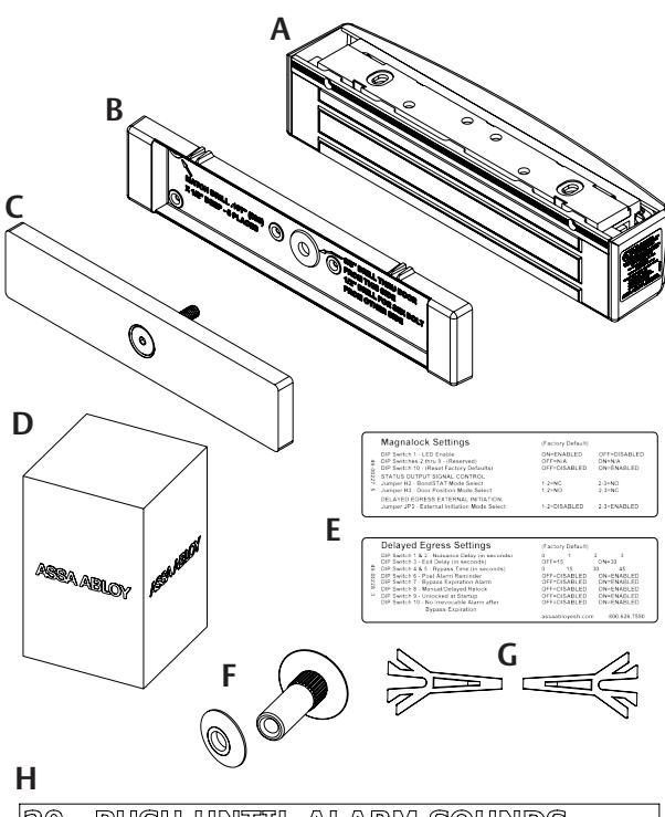
Product Components
A Magnalock & Mounting Bracket
B Strike Housing
C Strike Plate Assembly
D Wall Mounted Key Switch
E Settings Labels
F Sex Bolt & Tapered Washer
G Template Pins
H NFPA Door Label
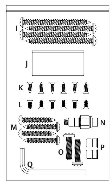
Installation Hardware Pack Contents
I #14 X 3" Type A Phillips Pan Head Screw (4)
J Threadlocker Packet
K WOOD DOORS: #6 X 1/2" Phillips Flat Head Type A Steel Screw (6)
L METAL DOORS: 6-32 X 3/8" Phillips Flat Head Type F Steel Screw (6)
M #12 X 1-1/2" Type A Phillips Pan Head Screw (4)
N Rivet Nut Install Tool
O 1/4-20 X 1" Phillips Pan Head Screw (2)
P 1/4-20 Rivet Nut (2)
Q 3/16" Hex Key
NOTE: Hardware is provided for various installations. There will be leftover parts depending on the type of installation.
Specifications
Dimensions
- Height: 2.50" [64 mm]
- Depth: 2.56" [65 mm]
- Length: 11.50" [292 mm]
Certifications
- UL 10C Fire Rated, 1 Hour
- CAN/ULC-S104 Fire Door Conformant
- UL 294
- UL Tested Ratings: Endurance: 100,000 cycles
- ANSI/BHMA A156.23, Grade 2; E18501 Compliant
- California State Fire Marshal Listed
- NFPA 101
Electrical
• Magnalock Minimum Current Draw (±10%)
95 mA at 12 VDC 65 mA at 24 VDC
• Magnalock Maximum Current Draw (±10%)
575 mA at 12 VDC 315 mA at 24 VDC
Static Holding Force
• 1,200 lbs [544kg]
Operating Temperature
- 32˚ to 120˚F [0˚ to 49˚C]
- Indoor use only
IMPORTANT This Magnalock requires calibration upon installation.
Diagram 1 Product Components
IMPORTANT: UL 294 compliance requires that the locking device be powered by a UL 294 (ALVY) or UL 603 (APHV) listed power supply and shall be installed in accordance with the following UL and National Standards: NFPA 70 – National Electrical Code.
Performing a pre-installation survey
-
1
Before installing the Magnalock, determine and assess the mounting location for the following:
- • Physical strength of the frame should be strong enough to meet or exceed the holding force of the Magnalock.
- • Frame and vicinity should offer protection for the wiring to prevent vandalism, and provide adequate protection from rain exposure.
- • Doorinspection inspect for any obstacles that may interfere when mounting the strike plate and ensure that there is minimum door movement when the door is latched.
- • Proper mounting —The Magnalock comes with factory default mounting hardware for use with an out-swing door.
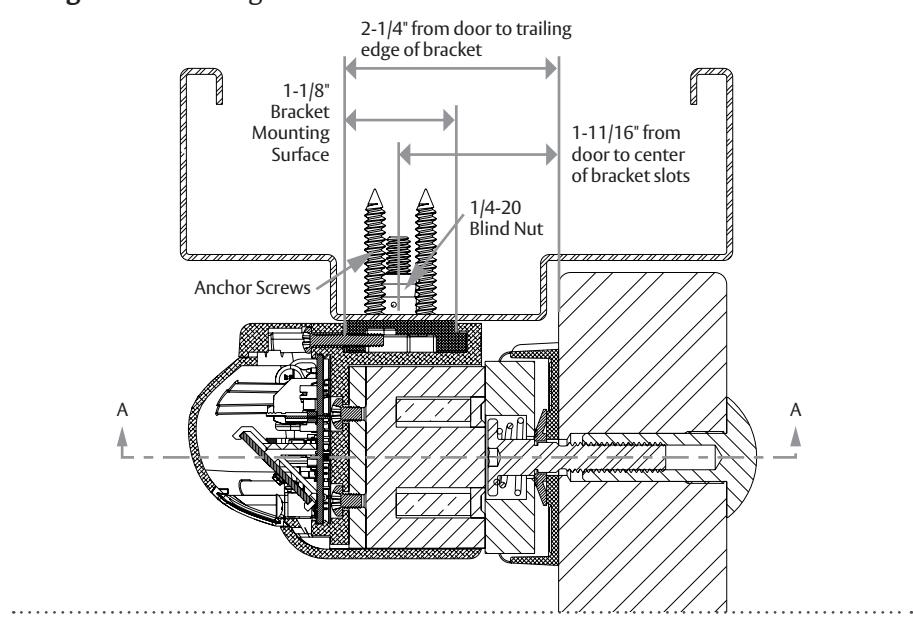
Diagram 2 Assessing the installation site
Preparing the Magnalock
1 Ensure that there is at least 2-1/4" between the closed door and the edge of the header. If not, a header bracket (sold separately) may be required (see Diagram 2) .
Removing the cover and mounting bracket
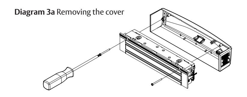
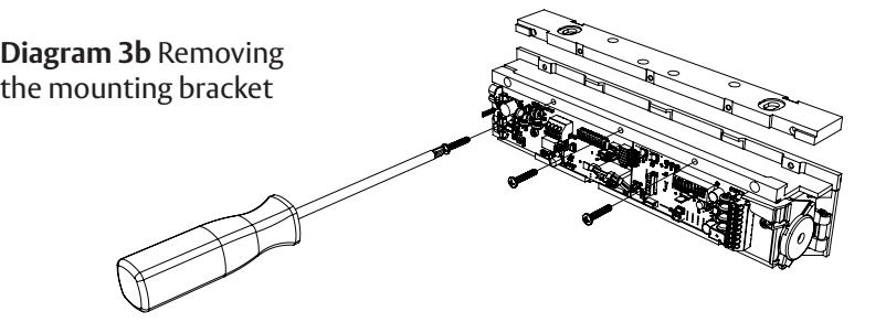
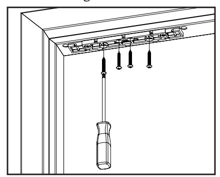
- 1 Using a Phillips screwdriver, REMOVE the two (2) screws that secure the cover, as shown in Diagram 3a , and the (3) screws that secure the mounting bracket to the top of the lock chassis as shown in Diagram 3b .
- 2 SET the cover and screws aside to re-attach later.
- 3 SLIDE the bracket to disengage from the top of the lock chassis.
Marking the frame
- 1 PINCH and insert the template pins flush into the dovetail slots of the mounting bracket (see Diagram 4) .
- 2 APPLY MASKING TAPE to the door and frame surfaces to protect from any possible damage during marking and drilling.
- 3 PLACE the mounting bracket against the frame stop on the secure side of the door and on the side of the door that does not have hinges. Ensure that there is a minimum a clearance of 1" from the frame.
- 4 CLOSE the door and adjust the bracket so that the template pins rest against the door.
Diagram 4 Inserting the template pins
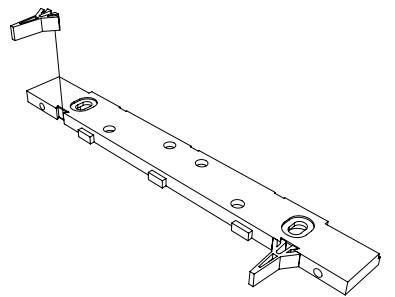
Diagram 5 Marking the frame
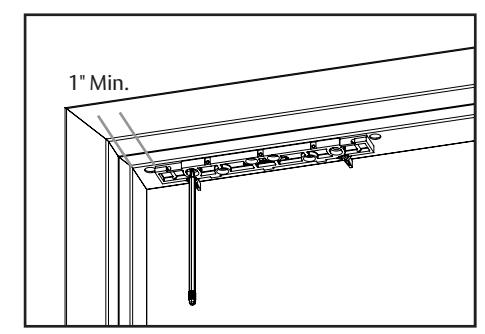
- 5 MARK the frame through the two (2) oblong (slotted) bracket mounting holes (see Diagram 5) .
- 6 MARK the frame for a wire feed-through hole at the end closest to where the wire run will be accessed and ensure the hole marking is centered at least 5/16" from the end and aligned with the rear edge of the bracket (see Diagram 6) .
- 7 REMOVE the mounting bracket from the frame.
Installing the Magnalock on a METAL DOOR frame
NOTE: Drilling a pilot hole first or using a step bit will ensure a snug fit for the blind nuts.
1 DRILL two (2) 3/8" diameter holes in the frame at the bracket mounting hole marks (see Diagram 7) . DO NOT oversize.
NOTE 1: Blind nuts provide a highly secure and tamperresistant system for mounting and are provided for this unit.
NOTE 2: A blind nut installation tool (Securitron BPT-2, Blind Nut Placement Tool, or similar) can be used instead of using a box end wrench and hex wrench.
-
2
INSTALL a blind nut into each 3/8" diameter hole using the provided tool (see
Diagram 8)
.
- Hold the collapsing nut with a 1/2" open or box end wrench.
- Maintain pressure against the mounting surface while tightening the cap screw using a 3/16" hex wrench to collapse the blind nut.
- 3 DRILL 1/2" diameter wire access holes as needed, on one or both sides of the bracket (see Diagram 9) .
- 4 REMOVE the protective tape from the frame.
- 5 Temporarily INSTALL the mounting bracket with template pins against the closed door using a Phillips screwdriver and two (2) 1/4-20 x 1" Phillips pan-head screws (see Diagram 10 ).
Installing the Magnalock on a WOOD DOOR frame
- 1 DRILL two (2) 3/16" diameter mounting holes by 1-1/4" deep at the bracketmounting hole marks (see Diagram 7) .
- 2 DRILL 1/2" diameter wire access holes as needed, on one or both sides of the bracket (see Diagram 9) .
- 3 REMOVE the protective tape from the frame.
- 4 Temporarily INSTALL the mounting bracket with the template pins against the closed door using a Phillips screwdriver and two (2) #12 x 1-1/2" Type A, Phillips pan-head screws (see Diagram 10 ).
Diagram 6 Marking the wire feed-through hole
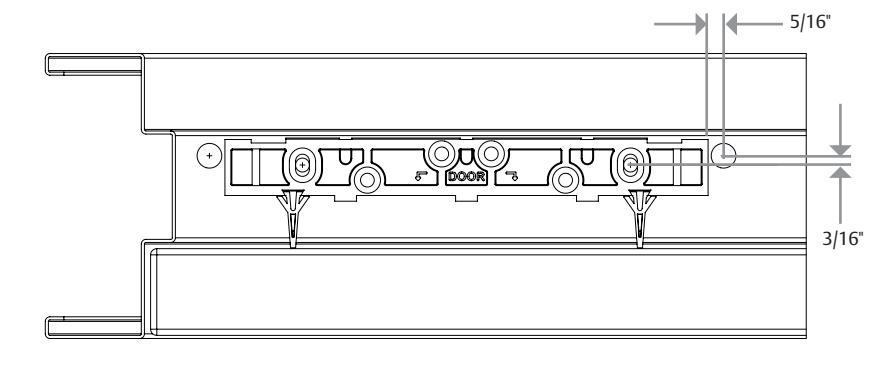
Diagram 7 Drilling the bracket mounting holes
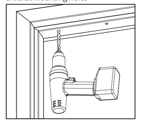
Diagram 8 Installing the blind nuts
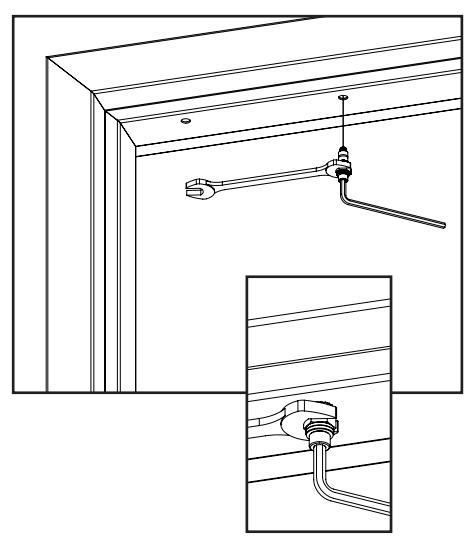
Diagram 9 Drilling the wire access holes
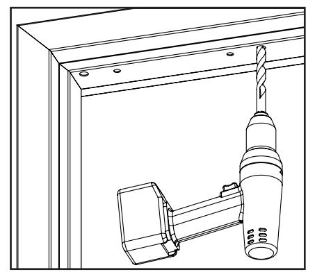
Diagram 10 Installing the bracket
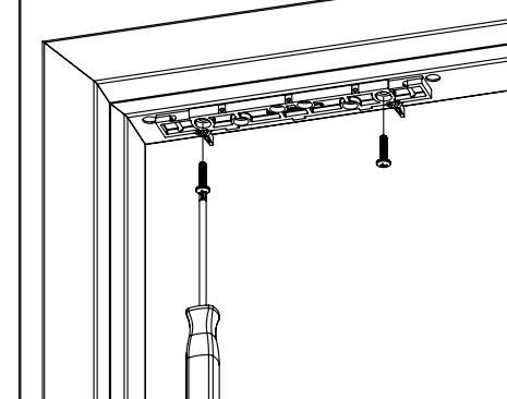
Installing the strike on the door
- 1 With the door closed, ALIGN the strike housing with the template pins as indicated on the strike housing. Ensure the strike housing is pushed up snug against the template pins.
- 2 MARK seven strike housing mounting hole locations (see Diagram 11 ).
- 3 REMOVE the strike housing from the door and the template pins from the lock mounting bracket.
From the INSIDE
- 4 DRILL a level 3/8" diameter hole for the sex bolt all the way through the door at the strike mounting center mark.
- 5 FOR A HOLLOW METAL DOOR: DRILL six (6) #36 (0.107") holes through the inside skin of the door for the strike housing mounting screws. FOR A WOOD DOOR: DRILL six (6) #36 (0.107)" x 1/2" deep holes for the strike housing mounting screws.
From the OUTSIDE
6 FOR A HOLLOW METAL DOOR: DRILL out the 3/8" diameter sex bolt hole to 1/2" diameter in the outside skin of the door (see Diagram 12 ). FOR A WOOD DOOR: DRILL out the 3/8" diameter sex bolt hole to 1/2" diameter completely through door.
Secure the strike plate assembly to the door
- 7 INSERT the sex bolt into the hole from the outside of the door (see Diagram 13 ).
- 8 ATTACH the strike plate housing using six (6) 6-32 x 3/8" Phillips flat-head screws for METAL –OR– six (6) #6 x 1/2" Phillips flat-head screws for WOOD door.
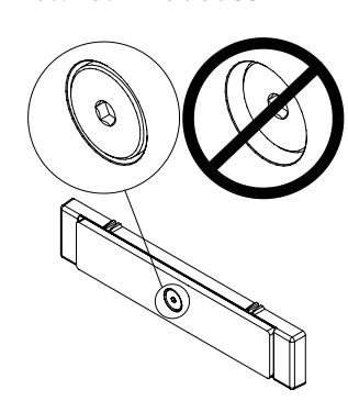
- 9 CRITICAL STEP: PLACE the tapered washer on the strike assembly screw with the smaller diameter surface of the washer facing against the back of the strike plate, as shown in Diagram 14 .
- 10 APPLY thread-lock compound (included) to the strike assembly screw.
- 11 INSERT the strike assembly screw through the strike housing and door and into the sex bolt.
- 12 CRITICAL STEP: TIGHTEN the screw into the sex bolt using the 3/16" hex wrench. While tightening, gently tap the head of the sex bolt using a rubber mallet until the head sits flush with the door.
NOTE: To provide maximum door movement after installation, the head of the strike assembly screw should be approximately 0.025" (about the thickness of a paperclip) below the surface of the strike as shown in Diagram 15 .
NOTE: DEM680E detects door movement through a concealed 'patent pending' strike assembly. OVERTIGHTENING the strike assembly screw will reduce door movement range and may cause false alarms. DO NOT OVERTIGHTEN the strike assembly screw.
Diagram 11 Marking the strike housing mounting hole locations from the inside
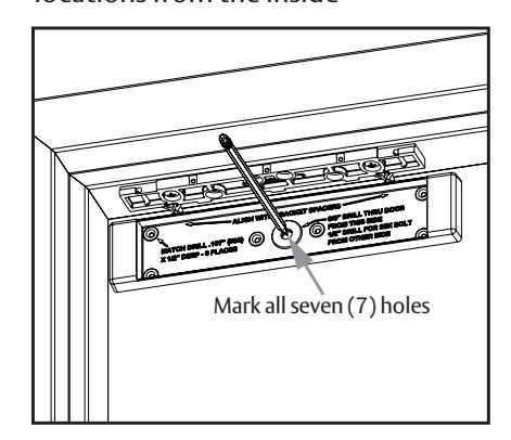
Diagram 12 Drilling the sex bolt hole from the outside
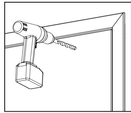
Diagram 13 Securing the plate assembly to the door
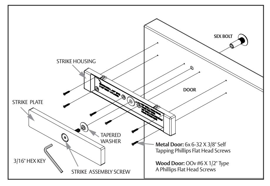
Diagram 14 Strike assembly installed – section view
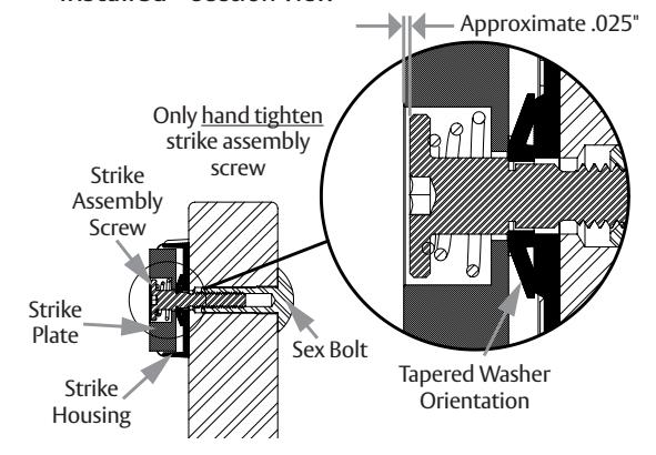
Diagram 15 Strike assembly installed – inside door
Mounting the Magnalock and aligning to the strike plate
- 1 SLIDE the Magnalock assembly to fully engage the lock chassis to the mounting bracket. Install one of the three screws through one of the top chassis holes and into the mounting bracket to temporarily secure the Magnalock (see Diagram 16 ).
- 2 SLIDE the lock forward or backward so that the entire face makes contact with the strike plate on the closed door.
- 3 MARK the back edge of the mounting bracket at each end and remove the Magnalock from the bracket (see Diagram 17 ).
- 4 ENSURE that the mounting bracket aligns with the marks and TIGHTEN the mounting screws (see Diagram 18 ).
holes and use #14 x 3" screws.
5 USING THE BRACKET AS A TEMPLATE, DRILL pilot holes as necessary, then install and tighten the four (4) final mounting screws (see Diagram 19 ). FOR HOLLOW METAL DOORS : DRILL 3/16" holes and use #12 x 1-1/2" screws. FOR WOOD DOORS: DRILL 7/32"
6 RETURN the Magnalock to the bracket and secure the chassis to the bracket with three (3) screws.
Diagram 16 Mounting the Magnalock to the bracket
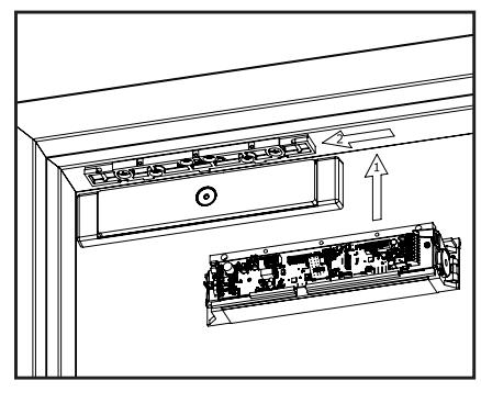
Diagram 18 Tightening the mounting screws
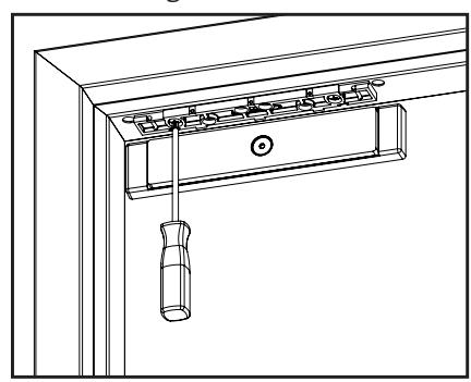
Diagram 17 Marking the back edge of the mounting bracket
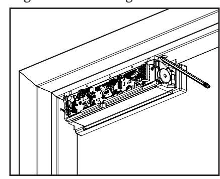
Diagram 19 Installing the final mounting screws
Installing the wall-mounted switch
- 1 ASSEMBLE the cylinder and switch to the wallmounted key switch plate (see Diagram 20 ).
- 2 MARK the corners for the mounting device at the desired locations on the wall and create a cut-out (see Diagram 21 ).
- 3 INSERT the mounting device into the cutout and fasten it in place with a Phillips screwdriver (see Diagram 22 ).
- 4 MAKE the wire connections and install the key switch plate using a flat-tip screwdriver and two 6-32 screws (see Diagram 23 ).
Diagram 20 Assembling the key switch plate
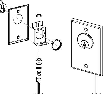
Diagram 22 Installing
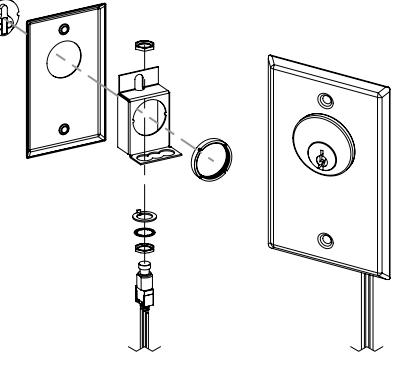
Diagram 23 Installing the key switch
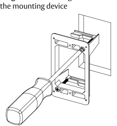
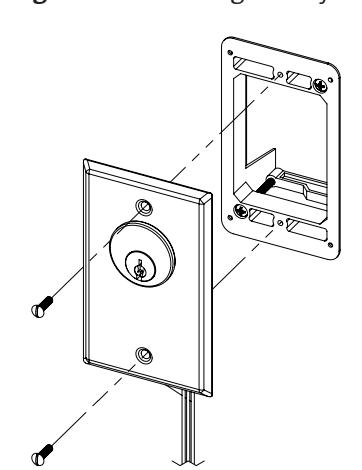
Diagram 21 Marking the wall cut-out
MAGNALOCK ELECTRICAL INSTALLATION
Pulling the wiring
NOTE: End-user and installer must comply with fire and building codes.
- 1 PULL wires/cables through the wire feedthrough hole(s) drilled in the frame.
- 2 INSTALL the provided wallmounted switch if necessary.
Connecting the final wiring
1 CONNECT the wires using Diagrams 24 through 28 as guides and as applicable.
NOTE: The positive terminal (+) and reference voltage (VREF) are internally bussed to provide a reference voltage for external control.
- 2 LOCATE the jumpers as shown in Diagram 29 .
- 3 SET the jumpers for the desired function using Table 1 .
- 4 LOCATE the DIP-switches as indicated in Diagram 30 .
- 5 Select the desired Magnalock functions using Table 2 and the desired delayegress functions using Table 3 .
Diagram 24 Location of J1 and J4 terminals
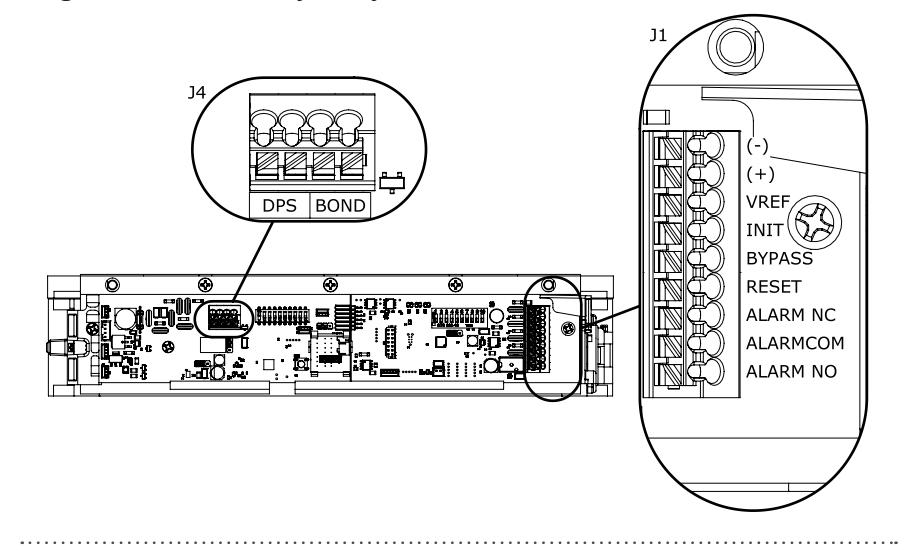
Diagram 25 Terminal pin-out diagram
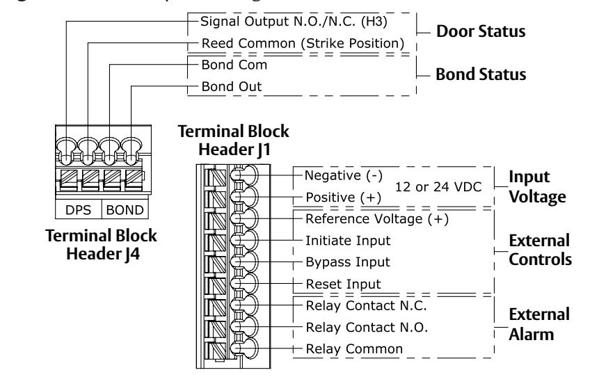
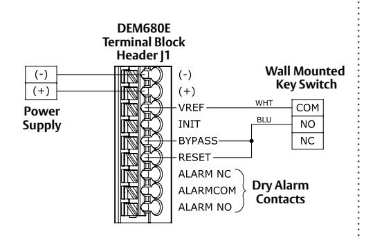
Diagram 26 Typical system wiring Diagram 27 Typical system wiring with external initiate device
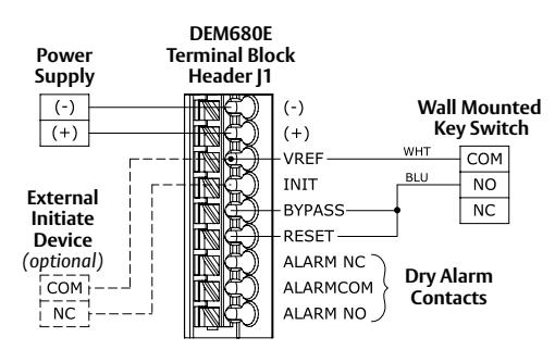
Diagram 28 Typical system wiring with external controls
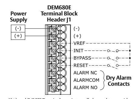
"(+) and "VREF" Terminals are internally bussed to provide reference (+) voltage external control use.
Diagram 29 Jumper Locations
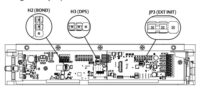
Table 1 Jumper Settings
| Jumpers | Posi | tion | Selection | Function/Description | Factory Default | |
|---|---|---|---|---|---|---|
| H2 (BOND) |
1
2 3 |
1-2 |
Normally
closed (NC) |
Normally closed circuit – opens when BOND registers secure. | Normally doesd | |
|
1
2 3 |
2-3 |
Normally
open (NO) |
Normally open circuit – closes when BOND registers secure. | Normally closed | ||
| H3 (DPS) | 123 | 1-2 |
Normally
open (NO) |
Normally open circuit
– closes when door opens. |
Normallyonon | |
| 123 | 2-3 |
Normally
closed (NC) |
Normally closed circuit
– opens when door opens. |
Normally open | ||
| JP3 (EXT INIT) | 123 | 1-2 | Disabled | When enabled, allows unit to | Disabled | |
| 123 | 2-3 | Enabled | be initiated from an external source. (J1, Terminal 4) | |||
Diagram 30 DIP-switch Locations
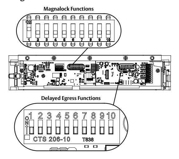
Table 2 Magnalock DIP-switch selection and function
| Magnalock function DIP-switches | Position | Selection | Function/Description | Factory Default |
|---|---|---|---|---|
| LED enable | SW 1 ON |
LED
enabled |
When enabled, LEDs
display lock status. |
ON |
| SW 1 OFF |
LED
disabled |
|||
| (Reserved) | SW 2 – SW 9 | N/A | Not used. | OFF |
| Reset to Factory Defaults | SW 10 OFF |
Reset
disabled |
When enabled, restores | |
| SW 10 ON |
Reset
enabled |
Magnalock firmware to factory settings. | OFF |
Table 3 Delayed Egress DIP-switch selection and function
| Delayed Egress Function Dip-Switches | Position | Selection | Function/Description | Factory Default | ||
|---|---|---|---|---|---|---|
| 1 2 3 4 5 6 7 8 9 10 | SW 1 OFF / SW 2 OFF | 0 seconds | 0 seconds | |||
| 5.1 | 1 2 3 4 5 6 7 8 9 10 NO NO NO NO NO NO NO NO NO NO NO NO NO | SW 1 ON / SW 2 OFF | 1 seconds | Time that the door must be pushed before | ||
| Nuisance Delay | SW 1 OFF / SW 2 ON | 2 seconds | triggering the irrevocable alarm cycle. Set the desired nuisance delay in seconds. | |||
| ☐ CTS 206-10 T838 | SW 1 ON / SW 2 ON | 3 seconds | , | |||
| Fuit Dolou | 1 2 3 4 5 6 7 8 9 10 | SW 3 OFF | 15 seconds | Set the desired irrevocable alarm interval in seconds. | 15 accorde | |
| Exit Delay | | | SW 3 ON | 30 seconds | WARNING: a 30 second delay must be approved by local code enforcement. | 15 seconds | |
| 1 2 3 4 5 6 7 8 9 10 | SW 4 OFF / SW 5 OFF | 0 seconds | The expected time for a door closure | |||
| Dumasa Tima | SW4ON/SW5OFF | 15 seconds | after manually bypassing (unlocking) | 0 seconds | ||
| Bypass Time | SW4OFF/SW5ON | 30 seconds | the system to exit or enter. | |||
| ☐ CTS 206-10 T838 | SW4ON/SW5ON | 45 seconds | Set the desired bypass time in seconds. | |||
| Post Alarm Reminder |
1 2 3 4 5 6 7 8 9 10
NO 0 0 0 0 0 0 0 0 |
SW 6 OFF | Disabled | When enabled, provides audible | Disabled | |
| POST AIdHII REIIIIIdei | ☐ ☐ ☐ ☐ ☐ ☐ ☐ ☐ ☐ ☐ ☐ ☐ ☐ ☐ ☐ ☐ ☐ ☐ ☐ | SW 6 ON | Enabled | indication after an alarm event. | ||
| Bypass Expiration | 1 2 3 4 5 6 7 8 9 10 | SW 7 OFF | Disabled | When enabled, provides audible indication | Disabled | |
| Alarm | ☐ ☐ ☐ ☐ ☐ ☐ ☐ ☐ ☐ ☐ ☐ ☐ ☐ ☐ ☐ ☐ ☐ ☐ ☐ | SW 7 ON | Enabled | when the bypass time has been exceeded. | ||
| Manual/Delayed | 1 2 3 4 5 6 7 8 9 10 | SW 8 OFF | Disabled | When enabled, the system automatically relocks 30 seconds | Disablad | |
| Relock | ☐ ☐ ☐ ☐ ☐ ☐ ☐ ☐ ☐ ☐ ☐ ☐ ☐ ☐ ☐ ☐ ☐ ☐ ☐ | SW 8 ON | Enabled | after an irrevocable alarm cycle. | Disabled | |
| 1 2 3 4 5 6 7 8 9 10 | SW 9 OFF | Disabled | When enabled, system starts | Disabled | ||
| Unlocked at Startup | T□ □ □ □ □ □ □ □ □ □ □ □ □ □ □ □ □ □ □ | SW 9 ON | Enabled | in the unlocked state. | ||
|
No Irrevocable
Alarm After Bypass |
1 2 3 4 5 6 7 8 9 10
NO 0 0 0 0 0 0 0 0 |
SW 10 OFF | Disabled | When enabled, prevents irrevocable alarm after bypass expiration. If SW7 | Disabled | |
| Expiration | | | SW 10 ON | Enabled |
is on, bypass expiration alarm repeats.
If SW7 is off, LED strobe flashes. |
Disabled | |
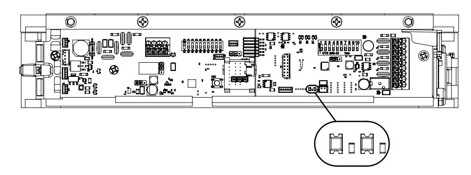
Delayed Egress status LEDs
The two LEDs shown display the following Delayed Egress states.
| RED | GREEN | STATE |
|---|---|---|
| OFF | OFF | Unlocked |
| OFF | ON | Bypass |
| ON | OFF | Egress Alarm |
| ON | ON | Locked |
Diagram 31 LED location
Documenting the configuration settings
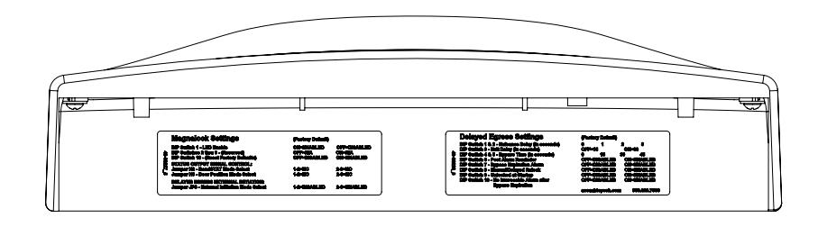
- 1 Indicate the settings on the adhesive-backed labels included with the Magnalock (see Diagram 32 ).
- 2 Complete the labels and affix them to the inside of the Magnalock cover (see Diagram 33 ).
Diagram 32 System settings
| Magnalock Settings | (Factory Default) | |||
|---|---|---|---|---|
| 49-0 | DIP Switch 1 - LED Enable DIP Switches 2 thru 9 - (Reserved) DIP Switch 10 - (Reset Factory Defaults) |
ON=ENABLED
OFF=N/A OFF=DISABLED |
OFF=DISABLED
ON=N/A ON=ENABLED |
|
| -00227_5 |
STATUS OUTPUT SIGNAL CONTROL:
Jumper H2 - BondSTAT Mode Select Jumper H3 - Door Position Mode Select |
1-2=NC
1-2=NO |
2-3=NO
2-3=NC |
|
|
DELAYED EGRESS EXTERNAL INITIATION:
Jumper JP3 - External Initiation Mode Select |
1-2=DISABLED | 2-3=ENABLED | ||
| Delayed Egress Settings | (Factor | y Default) | ||||
|---|---|---|---|---|---|---|
| 19-00220_3 | DIP Switch 1 & 2 - Nuisance Delay (in seconds) DIP Switch 3 - Exit Delay (in seconds) DIP Switch 4 & 5 - Bypass Time (in seconds) DIP Switch 6 - Post Alarm Reminder DIP Switch 7 - Bypass Expiration Alarm DIP Switch 8 - Manual/Delayed Relock |
OFF=D
OFF=D OFF=D |
15
ISABLED ISABLED ISABLED ISABLED ISABLED |
ON=
ON= ON= ON= |
45
ENABLED ENABLED ENABLED ENABLED ENABLED |
|
| assaan | loyesh.co | III ( | 300.626.7590 |
Diagram 33 Settings labels Behavior of Delayed Egress Magnalocks with regional settings
California
Upon power up, lock goes into an alarm state and requires a manual reset. Nuisance delay is settable to 0, 1, 2 or 3 seconds and the exit delay is fixed at 15 or 30 seconds. Bypass delay is settable to 0, 15, 30 or 45 seconds. A manual reset is required after a delayed egress event.
Chicago
Upon power up, lock goes into an alarm state and requires a manual reset. Nuisance delay is fixed at 1 second, the exit delay is fixed at 15 seconds, and the bypass delay is fixed at 0 seconds. A manual reset is required after a delayed egress event.
Initial calibration
NOTE 1: If calibration does not proceed according to the instructions below, please see the troubleshooting section at the end of the manual.
NOTE 2: Initial calibration can be performed with a 12-V battery for installations in facilities that do not yet have commercially-available power.
NOTE 3: Access control systems may register DPS and/or BOND error conditions during the calibration sequence.
TECH TIP: For installation on a door without a door handle, a pull handle can be made from masking or other tape to pull the door closed for calibration.
The DEM680E performs an automatic calibration when the unit is initially powered up. This process only proceeds if the door is closed and the unit has received acceptable signals from the DPS and bond sensors.
PERFORM a manual calibration immediately following installation, if necessary.
- 1 ENSURE that the door is closed.
- 2 APPLY power to the Magnalock.
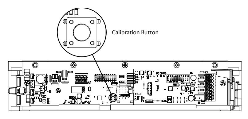
- 3 PRESS AND RELEASE the calibration button (see Diagram 34 ).
- 4 VERIFY that the LED changes from red to amber to green. The unit is now calibrated.
Diagram 34 Calibration button
Reinstalling the cover
NOTE: After wiring, settings, and calibration have been performed, and the system is functioning properly, the cover may be reinstalled on the Magnalock.
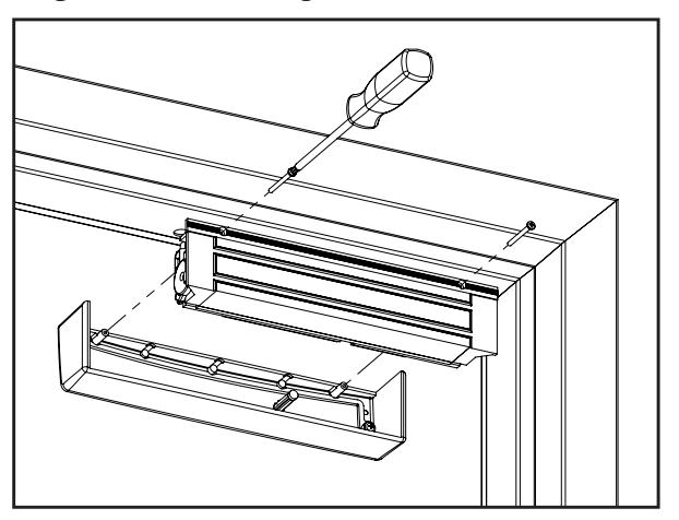
- 1 PLACE the cover over the rear of the Magnalock
- 2 INSTALL the two (2) Phillips screws to secure the cover (see Diagram 35 ).
- 3 APPLY the provided NFPA label with the appropriate (15 or 30 second) delay designation to the door.
Diagram 35 Reinstalling the cover
MAGNALOCK OPERATIONAL TESTS
Test 1 – Verifying correct startup
The DEM680E should be calibrated with a non-zero nuisance delay setting.
-
1 With the door closed
, the LED should be GREEN, indicating that it is active (see
Diagram 36
).
- If the LED is RED or AMBER, stop and consult the Troubleshooting Guide to correct.
Test 2 – Verifying door security
-
2 With the door closed
, PUSH against the face of the door WITHOUT releasing the primary locking mechanism (e.g., an exit device or cylindrical/mortise door lock). The nuisance alarm should not sound if the door is adjusted properly (see
Diagram 37
).
- • If the nuisance alarm sounds , there is too much door movement. The primary locking mechanism must be adjusted to reduce excessive door travel. Excessive movement will cause the DEM680E to go into alarm and unlock when the door is pulled from the unsecure side. Make necessary corrections and repeat Test 2.
Test 3 – Verify nuisance alarm function
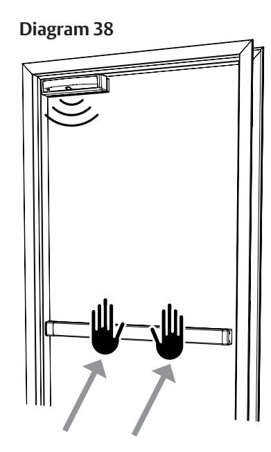
-
3
UNLOCK the primary locking mechanism (push bar or turn handle) and attempt to push the door open. The nuisance alarm should sound (see
Diagram 38
). Close the door before the nuisance interval expires to prevent the alarm state.
- • If the nuisance alarm does not sound , the strike assembly screw may have been overtightened. Overtightening prevents the door from traveling past the nuisance threshold. Refer to "No Alarm" in the Troubleshooting Guide and Diagram 14 which shows proper adjustment of the strike assembly screw.
Test 4 – Verify countdown alarm & free egress
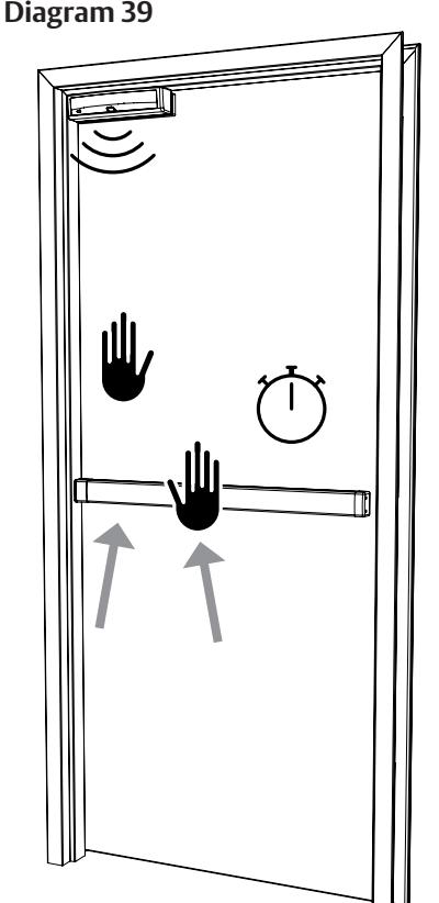
4 UNLOCK the primary locking mechanism and attempt to open the door. The nuisance alarm should sound along with a flashing strobe. Maintain pressure on the door until the alarm becomes steady; the DEM680E is now in alarm state. The door should open in 15 or 30 seconds, depending on the exit and nuisance delay settings. At the end of the alarm interval, the LED should turn red, and the door should freely open. (see Diagram 39 ).
*After testing, close the door and perform a reset. After reset, the strobe should turn off and the LED should change from red to green. VERIFICATION IS COMPLETE.
Diagram 36 Indicator light displays
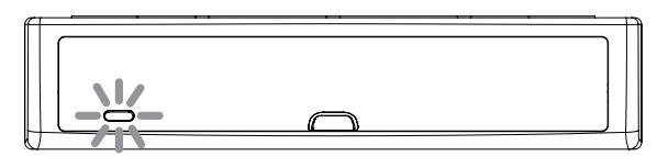
Diagram 37
Troubleshooting Guide
| TROUBLE INDICATOR | POSSIBLE CAUSES | POSSIBLE SOLUTIONS | ||
|---|---|---|---|---|
| Solid RED |
• Two bond sensor failures*
• Supply voltage < 8.5 VDC • Two bond sensor failures* |
• Ensure bond sensor connectors are properly seated
• Check power supply voltage • Ensure bond connectors are properly seated |
||
|
Solid RED with
Audible Alarm |
• Open door
• DPS failure* • Attempting to calibrate with two bond sensor failures* • Strike tray installed upside down • DPS magnet missing from strike tray |
• Close door
• Ensure DPS connector is properly seated • Ensure bond connectors are properly seated • Ensure that the strike tray is mounted with alignment tabs facing up • Check strike tray for damage, replace if needed |
||
| Solid AMBER |
• Door sag
• Obstructed strike/magnet face • Supply voltage < 10.8 VDC • Single bond sensor failure* • Magnet disconnected or magnet cable wire broken • Verify that the strike label has been removed |
• Recalibrate
• Check for obstructions between strike and magnet • Clean face of strike and magnet. Recalibrate • Check power supply voltage • Ensure bond connectors are properly seated • Make sure magnet connector is properly seated or repair magnet cable wire |
||
| Flashing RED | • Factory reset | • Ensure SW10 is in the OFF position | ||
| LED off |
• LED disabled by SW1
• Supply voltage < 5 VDC |
• Turn SW1 to the ON position
• Check power supply |
||
| Intermittent alarm | • Unscrew strike screw 1/2 turn at a time | |||
| No alarm | • Over-tightened strike screw |
until alarm sound is constant when door
is pushed (Recalibrate lock after each adjustment and repeat Install Verification) |
||
* Failure means that the circut cannot detect a signal from the sensor. Check that the sensor connectors are properly seated and inspect sensor wires for damage. Call Technical Support if replacement is needed.
Installing the NFPA label
NOTE: Each DEM680E comes with an NFPA exit delay door label as required by fire code.
1 FOLLOW the included application instructions to apply the lettering to a door.
Restoring factory default settings
- 1 DISCONNECT power from the Magnalock.
- 2 REMOVE the cover using a Phillips screwdriver.
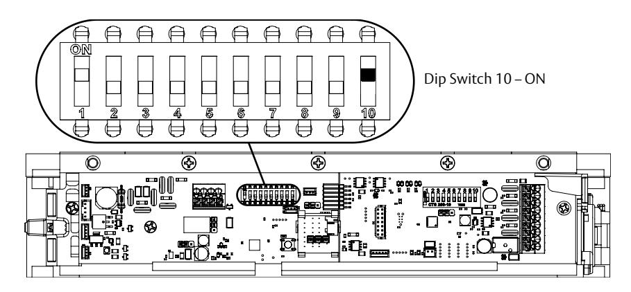
- 3 SET DIP-switch 10 (SW 10) to "ON" (see Diagram 40 ).
NOTE: When power is applied with SW 10 in the ON position, previous calibration settings are erased. The LED will continue to flash red until SW 10 is switched OFF.
- 4 APPLY power to the Magnalock and verify that the LED flashes red.
- 5 SET SW 10 to OFF. The unit should auto-calibrate. If the unit fails to calibrate see Troubleshooting Guide , or contact technical support.
Diagram 40 Setting DIP-switch 10 to ON
Warranty
For information on warranty coverage and replacement options, please visit securitron.com/warranty