Securakey Securelay Instructions
Open the original PDF document
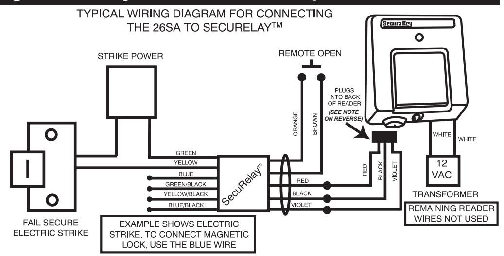
View PDFConnecting SecuRelay™ to an Entracomp® 26SA
- Splice the Red, Black and Violet wires to the enclosed Com Port Adapter which terminates in a snap-in plug. (You may splice in additional wire if the leads are too short.) Insert this plug into the 3-pin header on the 26SA. (SEE NOTE BELOW).
- Connect your electric locking device or gate operator to the SecuRelay™ using appropriate Common, Normally Open or Normally Closed circuits (see chart below).
- Connect the Orange and Brown wires to a normally open switch for Remote Open, if required.
Connecting SecuRelay<sup>™</sup> to a Radio Key<sup>®</sup> RK-65K or RK-65KS
TYPICAL WIRING DIAGRAM FOR CONNECTING THE RK65K OR RK100M TO THE SECURELAY
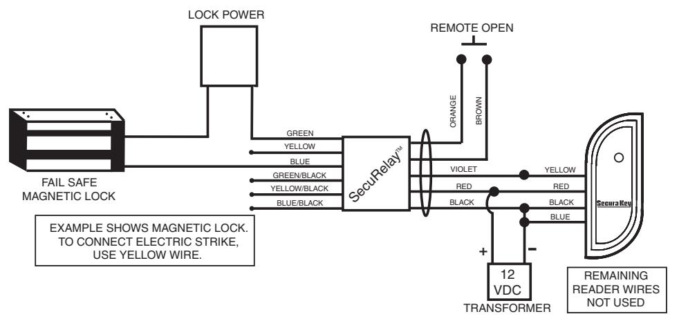
- Connect the Violet wire to the Yellow wire on the reader. Connect the Red wire to the Red wire on the reader and to positive DC power. Connect the Black wire to BOTH the Black and the Blue wires on the reader, and to negative DC power.
- Connect your electric locking device or gate operator to the SecuRelay™ using appropriate Common, Normally Open or Normally Closed circuits (see chart below).
- Connect the Orange and Brown wires to a normally open switch for Remote Open, if required.
Connecting SecuRelay™ to a Smart Reader (RKDT-SR / ET8-SR - use with NOVA.16)
READER POWER

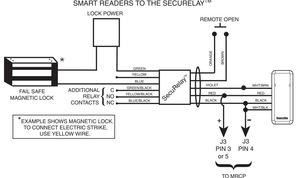
- . Connect SecuRelay Red to Reader Red (Power), connect SecuRelay Black to both Reader Black (Ground) and to Reader White/Black (Solid State Relay Ground), and connect SecuRelay Violet to Reader White/ Brown (Solid State Relay Signal).
- 2. Connect your electric locking device or gate operator to the SecuRelay, using appropriate Common, Normally Open or Normally Closed circuits (see wiring chart).
- Connect the Orange and Brown Wires to a normally open switch for Remote Open if required.
SecuRelay™ Installation Instructions
| SecuRelay™ WIRING CHART | |
|---|---|
| RED | +5-12 VDC |
| BLACK | - GROUND |
| VIOLET | SIGNAL |
| ORANGE | REMOTE OPEN |
| BROWN | REMOTE OPEN |
| GREEN | COMMON #1 |
| YELLOW | NORMALLY OPEN #1 |
| BLUE | NORMALLY CLOSED #1 |
| GREEN/BLACK | COMMON #2 |
| YELLOW/BLACK | NORMALLY OPEN #2 |
| BLUE/BLACK | NORMALLY CLOSED #2 |
Connects to Reader (26SA Uses Plug with Pigtail) *
NOTE: If your 26SA does not have a 3-pin header, see the wiring instructions below and consult the reader manuals for instruction on placing the unit in SecuRelay™ mode.
| SecuRelay™ | ENTRACOMP® 26SA |
|---|---|
| RED WIRE | RED WIRE (PIN 7) |
| VIOLET WIRE | YELLOW WIRE (PIN 3) |
| BLACK WIRE | BROWN WIRE (PIN 10) |
| N/A |
CONNECT GREEN WIRE (PIN 5)
TO BROWN WIRE (PIN 10) |
The SecuRelay<sup>™</sup> enhances the security of standalone access control products by removing the lock control relay from the access control unit and allowing the installer to locate it in a protected place. SecuRelay<sup>™</sup> learns the unique ID of a single access control unit and operates the DPDT dry contact relay only when a valid card causes that signal to be sent. Without a valid card there is nothing that an attacker can do at the access control unit that will activate the SecuRelay<sup>™</sup>.
Remote Open
The SecuRelay™ includes a Remote Open input which you may wish to utilize. (NOTE: This is the only option for Remote Open with the RK65K/KS and RKDT-SA access control units because the reader's Remote Open input is disabled when the SecuRelay mode is activated.) The SecuRelay Remote Open input will operate the relay for the time that the button is held, plus an additional 3 seconds. When The SecuRelay Remote Open input is used with Smart Readers and SK-NET, the Remote Open transaction will not be recorded in Transaction History and it will not be controlled by the latch timer value configured in SK-NET. (You may prefer to define an input on the Smart Reader as a remote open input.)
With the Smart Readers and 26SA, the reader's remote open input can be used, and the SecuRelay™ will operate for the time the button is held plus the access time configured in the connected access control unit.
Physical Installation
Install the SecuRelay™ in such a way that an intruder cannot reach it. If it is located in the wall or doorframe near the access control unit, take precautions so that it cannot be pulled out by the attached wires. We recommend that the body of the SecuRelay™ be physically attached to something, perhaps with nylon ties. You may want to locate the SecuRelay™ in a junction box with access only from inside the protected area. Keeping the amount of slack wire to a minimum will also prevent unauthorized access to the SecuRelay™. Also be sure that the Remote Open switch, if used, and the Orange and Brown wires are not accessible to any would-be intruder.
SecuRelay™ is well sealed but it should not be located in a wet location.
Initialize the SecuRelay™
- 1. Disconnect SecuRelay Red from Reader Power.
- 2. Temporarily short SecuRelay Orange and Brown wires
- 3. Reconnect SecuRelay Red to Reader (Power). SecuRelay is now in "learn mode."
- 4. Disconnect short between Orange and Brown wires.
- 5. For Smart Readers only, use SK-NET software to configure Smart Reader for SecuRelay operation (right-click Reader name, select Properties, Configuration Tab)
- 6. For all readers, activate by presenting a valid card to reader, or by activating a Remote Open input at the reader. Reader sends serial number to SecuRelay, where it is retained in non-volatile memory.
FCC Warning: This device complies with Part 15 of the Class B FCC rules. Operation is subject to the following two conditions: (1) This device may not cause harmful interference and (2) this device must accept any interference received, including interference that may cause undesired operation.