Securakey SKACP User Installation Manual
Open the original PDF document
View PDFSK-ACP User/Installation Manual

COPYRIGHT© 2009 SECURA KEY a division of SOUNDCRAFT INC.
SK-ACP TABLE OF CONTENTS
| 1. |
INTRODUCTION
1 |
|---|---|
|
Introduction to SK-ACP
Card ID Numbers and Facility Codes |
|
| 2. |
INSTALLATION
4 Physical Installation Wiring Power and Batteries Readers Inputs Outputs RS-232 Connections RS-485 Connections |
| 3. |
PROGRAMMING THE SK-ACP WITH SK-NET™
11 |
| 4. |
FACTORY SETTINGS
12 |
| 5. |
READERS AND CARDS
13 Secura Key Readers and Cards Ordering Additional Cards Setting Facility Codes |
| APPENDIX A – Wiring and System ConfigurationsA-1 | |
|
APPENDIX B – SK-NETTM Equipment Components and Specifications
B-1 |
|
| APPENDIX C – Connecting a Modem to SK-ACPC-1 | |
| APPENDIX D – Connecting an SK-ACP to a Local Area NetworkD-1 | |
|
APPENDIX E – SK-ACP Troubleshooting Guide
E-1 |
|
| APPENDIX F – Preventing Lightning DamageF-1 | |
|
V0102009 3321436
(7354) |
INTRODUCTION
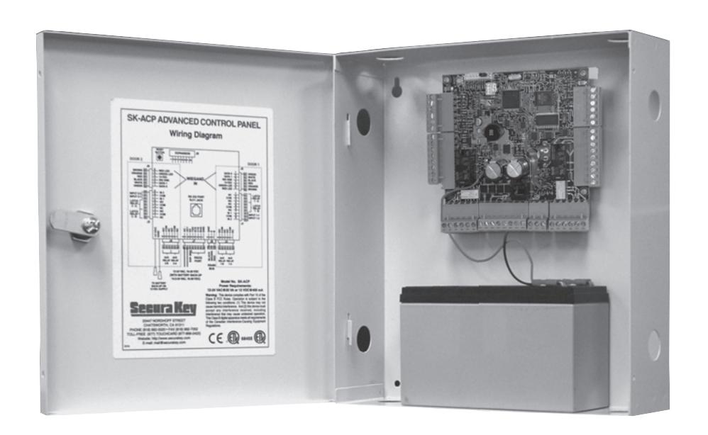
The SK-ACP Advanced Control Panel is a highly sophisticated, yet simple to use, two door access control unit. The unit accepts readers of almost any technology, with a Wiegand output up to 40 bits, including Proximity, Touch Card, Wiegand, Magnetic Stripe, Bar Code, Optical, and Biometric. Each of the two passageways controlled by the unit is completely independent of the other and is configured, programmed and viewed separately.
Up to 100 SK-ACP Panels may be linked together on a twisted pair (plus signal ground) RS-485 bus. When used with SK-NET™ software, a highly featured, easy to use, distributed intelligence access control system can be created.
Each of the two passageways controlled by the SK-ACP has two programmable inputs which may be programmed by the user to function as a Door Monitor, Tamper Monitor, Remote Open, Remote Inactive, Bell, Arming Circuit, or User Defined Input.
Each of the two passageways controlled by the SK-ACP has two outputs. One output is the Relay that operates the door operating device. The other output is programmable by the user to activate under one of several possible alarm or special conditions.
SK-ACP will control access for up to 65,535 individuals in 15 weekly time schedules (Time Zones) independently for each of the two passageways. Time Zones include a holiday schedule that is followed when one of the 32 user programmable holidays occur.
Certain Access Cards may be designated as "Limited Use" cards, and their use may be restricted to allow access for a given number of days or weeks or for a given number of times.
The SK-ACP may be programmed with a terminal or PC. Transaction information is stored by the unit and may be downloaded to a terminal, PC, or serial printer. Up to 4,864 transactions are stored.
Since the SK-ACP has nonvolatile memory, reprogramming after a power loss is unnecessary.
CARD ID NUMBERS AND FACILITY CODES
Access cards used with the SK-ACP have two encoded numbers: the ID number which is different on each card, and the Facility Code, (also called a system or site code) which is normally the same for all cards at a given site. When a card is read, the system first verifies the Facility Code, then it checks the ID Number against its internal "card list" in memory to see if the card is void or valid. It also checks the Time Zone, the card's Antipassback status, and the Limited Use count.
SETTING THE FACILITY (SYSTEM) CODE
IMPORTANT
Before programming or using a new unit, the correct Facility Code must be set.
When power is first applied, or when the reset button is pushed (see Figure 3) the LED on each of the two readers will flash red and green alternately. While the LED is flashing, present an Access Card with the proper facility code to one of the readers and remove it (note LED turns solid green for about 1 second and the beeper beeps to indicate that the card has been read). The SK-ACP will "remember" the facility code and retain it until reprogrammed. It is not necessary to present the access card to the second reader since it is automatically set for both passageways. After setting the facility code, wait for the LED to stop flashing before attempting to use the reader.
To change a facility code (or to set the facility code if the LED is not flashing red/green), momentarily depress the reset button. The LED indicator will flash red and green alternately. If the reset button is pushed, but no card is presented to the reader before the LED indicator times out, the system code will be unchanged.
In some cases it may be necessary for the unit to recognize more than one facility code. Typical instances are when it is necessary to read cards that work in two independent locations that already have different facility codes or when two different reader technologies are used in the same system, each of which has a different facility codes.
The SK-ACP can be set to recognize up to sixteen different facility codes. To program multiple facility codes, follow the procedure above for programming a single facility code, but present a card with the second facility code (and additional facility codes if necessary) to the reader before the red/green LED indicator times out.
Note that it is not generally recommended to combine sets of cards with different facility codes, because the unit cannot distinguish between access cards having different facility codes and the same ID number.
For example, if you have two sets of cards numbered 1-100, with facility codes 12345 and 23456, and you delete cards 1 - 10 from the reader's internal "card list," then cards 1 - 10 with either facility code will be denied entry at the reader.
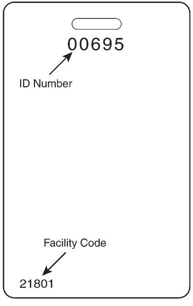
FIGURE 1
INSTALLATION
CAUTION SHOULD BE TAKEN NOT TO TOUCH CIRCUIT BOARD OR ELECTRONIC COMPONENTS PRIOR TO AND DURING INSTALLATION TO AVOID ELECTRO-STATIC DISCHARGE (ESD) DAMAGE.
INSTALLING THE SK-ACP
- 1. Select a location for the SK-ACP unit that is secure and sheltered from weather and extreme humidity. Choose a location that facilitates access to power and is reasonably close to the doors that are to be controlled (no further than 500 feet).
- 2. Using the unit as a template, mark on the mounting surface the location of the four mounting holes.
- 3. Install appropriate mounting hardware (anchors, retainers, etc.) to the mounting surface if necessary.
- 4. Screw #6 or #8 mounting screws into the top 2 mounting holes of the mounting surface, leaving about 1/4" clearance.
- 5. Place panel top key-way mounting holes over installed mounting screws and slide panel down.
- 6. Tighten top mounting screws.
- 7. Install two bottom mounting screws (see figure 2).
- 8. Route cables into the enclosure through knockouts in sides or back of box, being careful not to nick or scrape insulation on any rough edges.
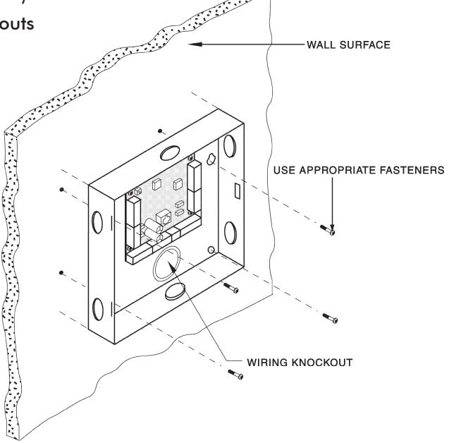
FIGURE 2
WIRING
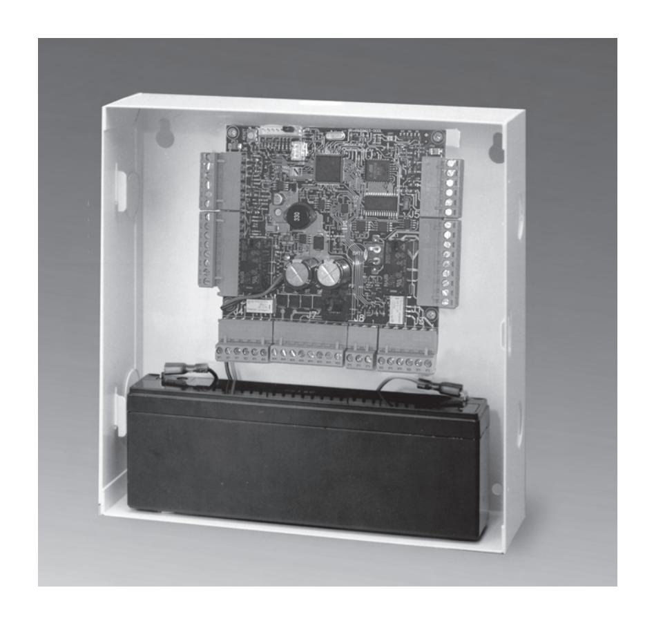
The SK-ACP unit is organized so that the wiring for door #1 is on the right side of the panel and the wiring for door #2 is on the left side of the panel (see figure 3).
For ease of installation and servicing, plug-in terminal blocks are provided.
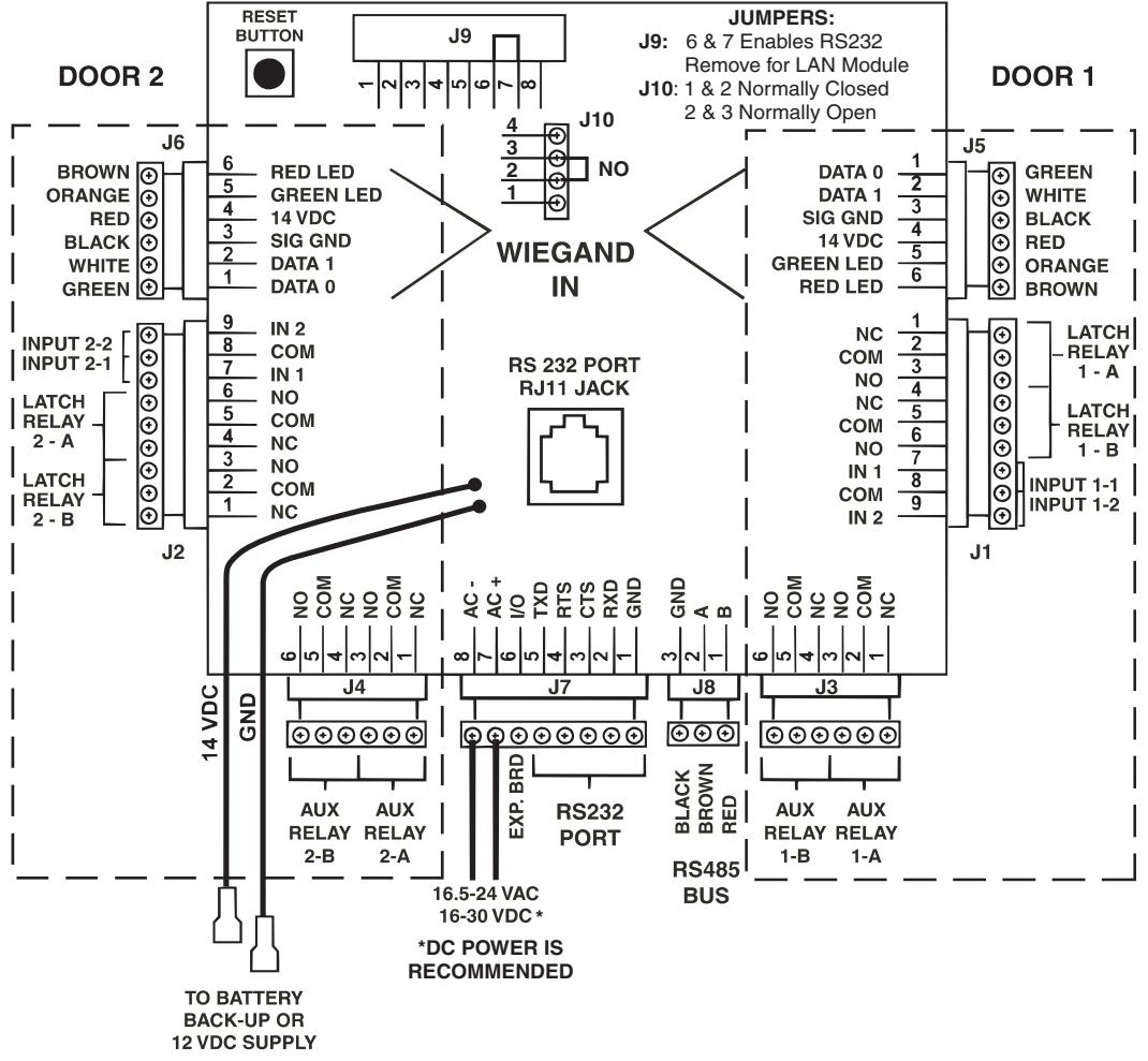
FIGURE 3
POWER & BATTERIES
The SK-ACP unit must be connected to a source of low voltage power. The SK-ACP should NOT be connected to the same power supply that is providing power to an electric lock or strike. To power the SK-ACP, you must use a power supply, which is properly rated for the panel, plus any connected equipment:
SK-ACP with RK-WM / RK-WS readers 24VDC, 500 mA SK-ACP with SK-LAN-MOD or SK-WLS-MOD 24VDC, 1 Amp Add RK-WL readers to either of the above 24VDC, 1.5 Amp
The basic configuration can be powered by the SK-ACP-PS, which includes a 24VDC 500 mA supply and a 1.9AH backup battery.
Terminals 7 & 8 on plug "J7" must be connected to 16.5 to 24 volts, AC or DC. DC power is recommended. AC power can be used but reader performance can be affected in areas where local power is not "clean". You may also connect the SK-ACP to 12 VDC, but in this case you must connect your power supply to the red (+) and black (-) wire leads on the lower left corner of the panel instead of the "J7" plug. If you use 12 VDC you cannot install a standby battery in the SK-ACP.
When 16.5 – 24 volts is used to power the SK-ACP, you may connect the red and black wires to a 12 volt standby battery. Polarity (+/-) must be observed. The standard SK-ACP has space for a small (1.9AH) battery, while the 10" X 11" SK-ACP-LE can accommodate larger batteries. A battery up to 4.5 Amp-hours can be connected to each SK-ACP.
Do not energize the SK-ACP until all other connections are made.
READERS
SK-ACP is designed to accept any reader or keypad with a standard Wiegand interface. The reader for door #1 is connected to plug "J5", the reader for door #2 is connected to plug "J6". (See figure 3) SUGGESTED CABLE IS Alpha 1296C. The SK-ACP will provide up to 150mA to power each reader. If the readers you use require more current, an external power supply must be used.
INPUTS
Each reader may be associated with up to two auxiliary inputs. Inputs might include remote switches, door contact sensors, vehicle presence detectors, etc. If you connect inputs to the SK-ACP you must define those inputs using SK-NET™ software (see SK-NET™ manual, section 5.31). Note that input 1 (#7) and input 2 (#9) share a common terminal (#8) on plugs "J1" and "J2". All inputs are configured as normally open circuits. However, in many cases a "Door Monitor" input should be a normally closed circuit. To convert any input defined as "Door Monitor" to normally closed, disconnect power from the panel, remove the jumper from pins 2 and 3 on connector J10 and place the jumper on pins 1 and 2. Restore power to the panel and test the door monitor input.
OUTPUTS
Each door controlled by the SK-ACP has two double pole, double throw relays associated with it. The "latch relays" are located on "J1" and "J2", terminals 1-6. The "auxiliary relays" are located on "J3" and "J4". One pole of the latch relay is typically used to open or close a circuit to unlock a door or activate a gate operator. The other pole of the latch relay operates simultaneously and may be used to shunt an alarm contact, start a video recorder, etc. The auxiliary relay may operate according to a variety of user-defined conditions. These must be programmed using SK-NET™ software (see SK-NET™ manual, section 5.33) NOTE: Two MOVs (metal-oxide varistors) are provided with each SK-ACP. These must be installed between the "Common" and either the "Normally Open" or the "Normally Closed" terminals where power to the electric lock or strike is being switched (See Figures 6 and 7). For testing and troubleshooting purposes, an LED indicator is located on the circuit board adjacent to each relay. The LED lights when the relay is activated.
COMMUNICATIONS JUMPER
The jumper on pins 6 and 7 of expansion connector J9 must be installed to enable RS232 communications at the RJ11 Jack, PJ1. If either the SK-LAN-MOD Network Module, or the SK-WLS-MOD Wireless Network Module is installed at J9, the jumper must first be removed from Pins 6 and 7. When installed, the network module will connect pins 6 and 7 internally, enabling the RJ11 Jack.
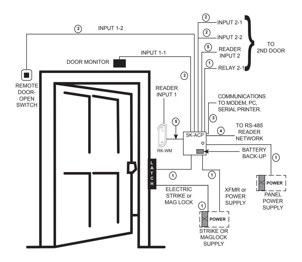
CABLE TYPES: 1
- 2 COND, UNSHIELDED 16-18 AWG
- 2 COND, UNSHIELDED 18-24 AWG 2
- 6 COND, SHIELDED 18-24 AWG 3
- RS-485 CAT 5 NETWORK CABLE OR TWO TWISTED PAIR 4
- 6 CONDUCTOR SHIELDED, WITH NO TWISTED PAIRS
FIGURE 4
| PIN NUMBER CONNECTIONS | ||||||
|---|---|---|---|---|---|---|
| SK-ACP ADVANCED CONTROL PANEL | PC OR TERMINAL |
SK-LAN OR
MODEM |
MODEM | |||
| J7 |
DB-25S
(FEMALE) PIN # |
DB-9S
(FEMALE) PIN # |
DB-25P
(MALE) PIN # |
DB-25P
(MALE) PIN # |
DB-9P
(MALE) PIN# |
|
| 1 | 1 & 7 | 5 | 1 & 7 | 7 | 5 | |
| 2* | 2 | 3 | N/C * | 3 | 2 | |
| 3 | 4 | 7 | 20 | 8 | 1 | |
| 4* | 5 | 8 | 6 & 8 | 4 | 7 | |
| 5 | 3 | 2 | 3 | 2 | 3 | |
| PRINTER | ||||||
FIGURE 5
RS-232
You may connect RS-232 communications to the SK-ACP either by using plug "J7", terminals 1-5, or by plugging into the RJ11 jack in the center of the circuit board. (See figure 3) RS-232 requires at least 5-conductor cable. SUGGESTED CABLE IS Belden 9535. RS-232 is used to connect the COM port of a PC to a single SK-ACP, or as a gateway to a network of SK-ACPs. (COM ports are typically DB9 male or DB25 male jacks on the back of a personal computer.) When connecting a PC via RS-232 the distance from the panel to the computer should not exceed 100'. (For longer distances, see "RS-485" below.) A serial printer may also be connected to the RS-232 port of any SK-ACP. This will allow all system transactions to be printed as they occur. (A printer may be connected to one SK-ACP even if a computer is connected to another SK-ACP in the same network.) An external modem might also be connected to the RS-232 port of an SK-ACP for dial-up applications using SK-NET-MLD software. While any Hayes compatible 56K modem may be used, we highly recommend that you use the Secura Key SK-MDM. The SK-ACP contains the configuration data, or "setup string" which allows this modem to be configured in the field without the use of a computer and without setting DIP switches. (See Appendix C for modem instructions.) Figure 5 shows the RS-232 pin connections for a PC, printer, or modem. WARNING: Never connect a telephone line directly to the RJ11 jack on an SK-ACP!
Installation of Metal Oxide Varistor with Electric Strike
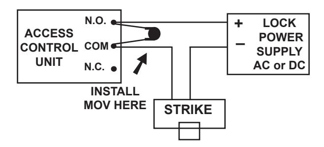
Install the enclosed 40-volt MOV (Metal Oxide Varistor) across the relay contacts in the access control unit, as shown. The Access Control Unit must have its own power supply.
FIGURE 6
Installation of Metal Oxide Varistor with Magnetic Lock
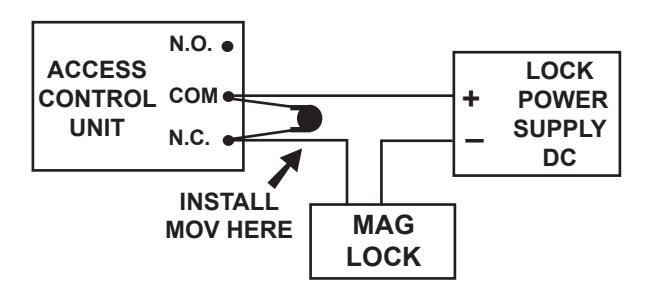
Install the enclosed 40-volt MOV (Metal Oxide Varistor) across the relay contacts in the access control unit, as shown. The Access Control Unit must have its own power supply.
FIGURE 7
RS-485
The RS-485 bus is used to link multiple SK-ACP units into a network. Where two or more SK-ACPs are linked, you must run cable between the "J8" plugs on each panel. Terminals 1 & 2 must be a twisted pair of wires. SUGGESTED CABLE is Belden 1585A (CAT-5e). Terminal 3 is a "signal ground". Normally, it does not need to be connected. However, if terminal 3 is used, it may be connected to one conductor of another twisted pair. This must be an insulated conductor and it should NOT be connected to earth ground.
Where the distance from the PC to any one of the SK-ACP units is greater than 100', you may install an RS-232 to RS-485 converter (Secura Key p/n NET-CONV-P) to the COM port of the computer. From the converter you then run RS-485 cable and connect it anywhere along the RS-485 bus. The total RS-485 cable distance, including the distance between all SK-ACPs, may be up to 4000'.
Figure 8 shows how each SK-ACP is connected to the RS-485 bus.
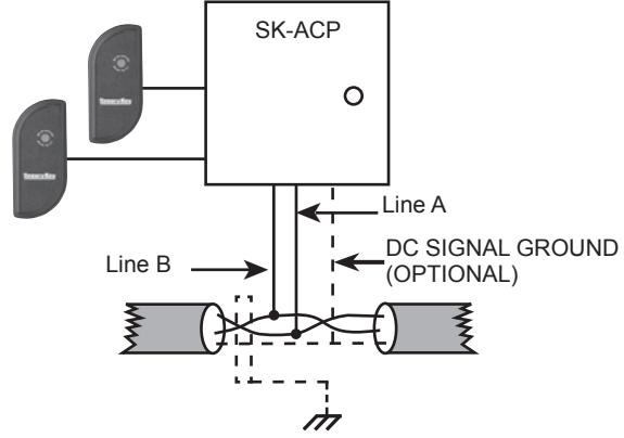
Earth Grounded Shield is highly recommended in environments subject to high voltage electrical discharge (i.e. lightning). Shield should be connected to earth ground only at one end of the cable. DC Signal ground may be necessary in networks with very long wire runs. DC Ground wire is NOT to be connected to earth ground.
FIGURE 8
PROGRAMMING THE SK-ACP WITH SK-NET™
The SK-ACP must be programmed with SK-NET™ software. Please refer to the SK-NET™ manual for programming instructions. (The SK-NET™ manual is available at www.securakey.com)
FACTORY SETTINGS
When shipped from the factory, the SK-ACP has the following settings:
Facility Code None*
All Cards Time Zone 0 (void)
No Limited Use Cards
Settings Latch timer = 1 Second
APB Timer = 0 Minutes (off)
Baud Rate = 38,400* Reader ID = (none) Password = 12345* Date = Undetermined* Time = Undetermined*
Time Zones APB = Timed Hard*
Date Restrictions = None
0 = Always Void
1 = Always Valid (no restriction) 2 = Mon - Fri, 8am - 5:30pm 3 = Mon - Fri, 6am - 6pm 4 = Sat & Sun, 24 hours 5 = Sat & Sun, 6am - 6pm
6 = Always Valid (Timed Antipassback)
7 & Up = Mon-Sun, 6am - 6pm
Door Zone Off For All Time Segments
Holidays None Set
Daylight Savings
Correction Automatic* Inputs 1 Door Monitor 2 Disabled Auxiliary Output Disabled
Anti-Passback Parameters
Reader (In/Out) None Daily APB Forgive Hour 00
* Common to Panel, all other settings are per reader (2 readers per panel)
READERS AND CARDS
USING SK-ACP WITH SECURA KEY PROXIMITY READERS AND CARDS
Secura Key offers proximity and contactless smart card readers in a variety of sizes for use with the SK-ACP panel. Secura Key readers read Secura Key cards only. Secura Key cards have two encoded numbers: the ID Number which is different on each card, and the Facility Code (also called a system or site code) which is normally the same for all cards at a given site. When a card is read, the system first verifies the Facility Code, then it checks the ID Number against its internal "card list" to see if the card is void or valid. It also checks the card's Antipassback Status, Time Zone and Limited Use count.
ORDERING ADDITIONAL CARDS FOR YOUR SYSTEM
The SK-ACP can learn up to 16 different facility codes, but it is not generally recommended that you combine sets of cards with different Facility Codes in the same system. The SK-ACP cannot distinguish between cards which have different Facility Codes and the same ID Number. For example, if you have a card with Facility Code A1 and ID Number 15 and you have a card with Facility Code B2 and ID Number 15, and the SK-ACP has been programmed to accept both Facility Codes, it will see these as the same card.
When ordering additional cards it is recommended that you place a factory order specifying the existing Facility Code and beginning with the ID Number which is one higher than the highest card already in use.
SETTING THE FACILITY CODE
When power is first applied to the SK-ACP the LED on each of the connected readers will flash alternately Red and Green. While the LED is flashing, hold an Access Card with the correct Facility Code near a reader for about one second. The LED should show a long Green flash and the reader will beep. If an additional Facility Code is to be entered, present an Access Card with that Facility Code in the same manner. Repeat
for each Facility Code to be entered. Let the LED stop flashing Red/ Green before attempting to use an Access Card.
To change a Facility Code (or to set a Facility Code if the LED is not flashing Red/Green) momentarily depress the reset button on the SK-ACP. Depressing the reset button will NOT erase memory or disrupt other programming.
To add an additional Facility Code to a system, while retaining the existing Facility Code, you must depress the reset button and then present a card with each Facility Code to the readers while the Red/ Green flashing is occurring. If you only present a card with the "new" Facility Code the system will "forget" the old Facility Code.
It is only necessary to present an Access Card to one of the two readers connected to each SK-ACP in the system.
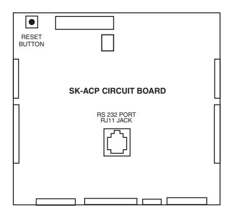
FIGURE 14
APPENDIX A
WIRING AND SYSTEM CONFIGURATIONS
MULTI-PANEL SYSTEM USING SK-NET™ SOFTWARE- SINGLE LOCATION RS-232 CONNECTION
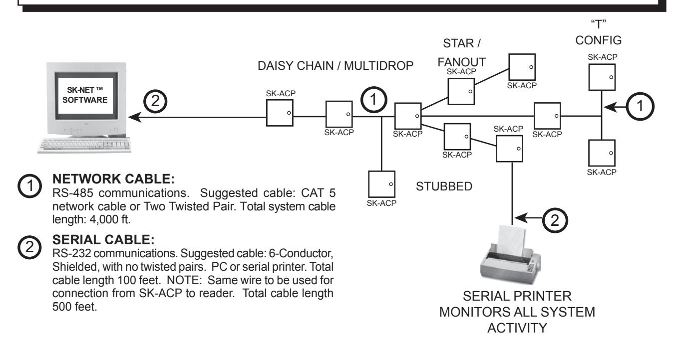
NOTE: Each SK-ACP above can support 2 Wiegand output card readers.
MULTI-PANEL SYSTEM USING SK-NET™ SOFTWARE- SINGLE LOCATION RS-485 with CONVERTER
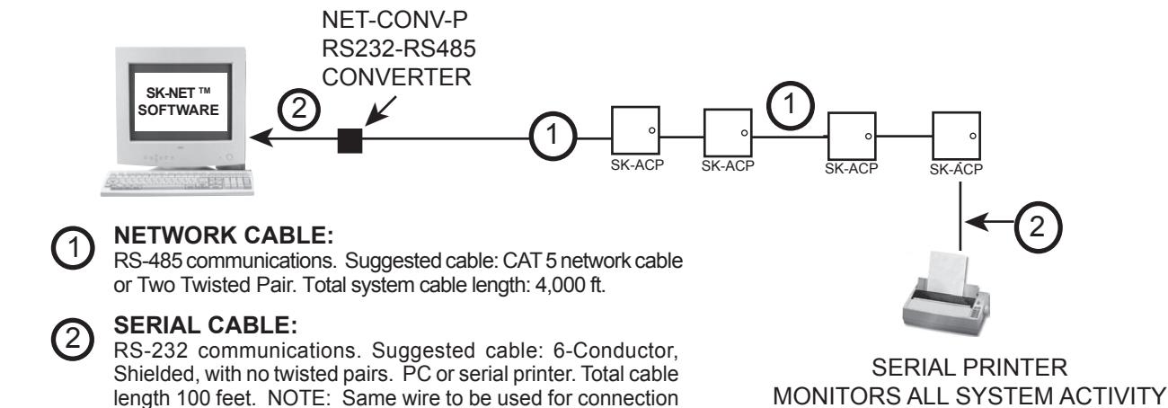
Note: When using the RS-232 to RS-485 converter, you cannot use the stubbed, star fanout or "T" configuration. All network connections from SK-ACP to the next SK-ACP must be in parallel with each other. The J8 connector, Pins 1 and 2 must be a twisted pair. Pin 3 (Ground) is not connected.
from SK-ACP to reader. Total cable length 500 feet.
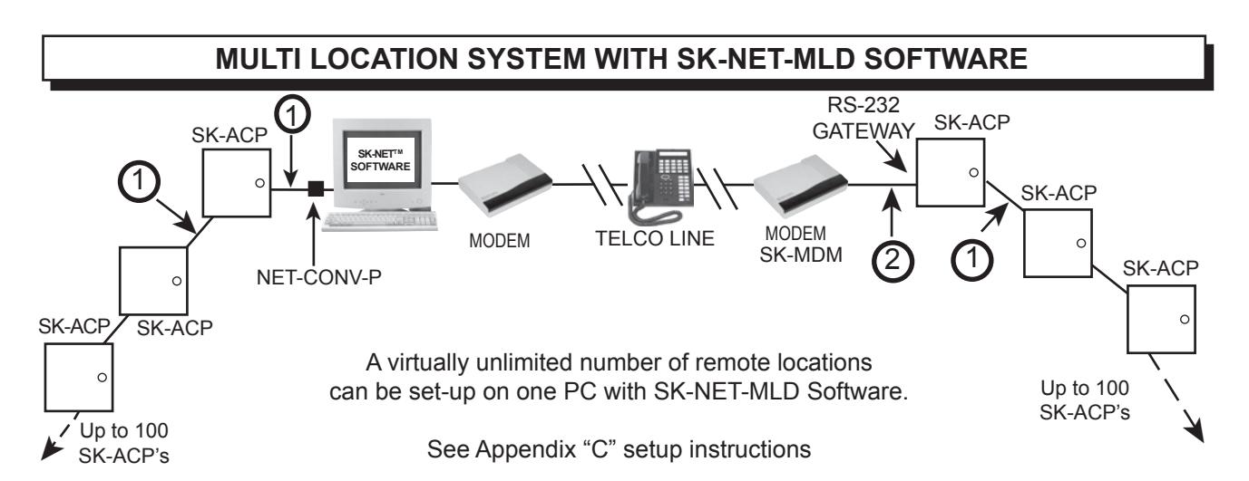
MULTI-PANEL SYSTEM USING SK-NET™ SOFTWARE- SINGLE LOCATION WITH SK-LAN
NOTE: SK-NET-MLD software must be used when connecting the SK-LAN External Device Server.
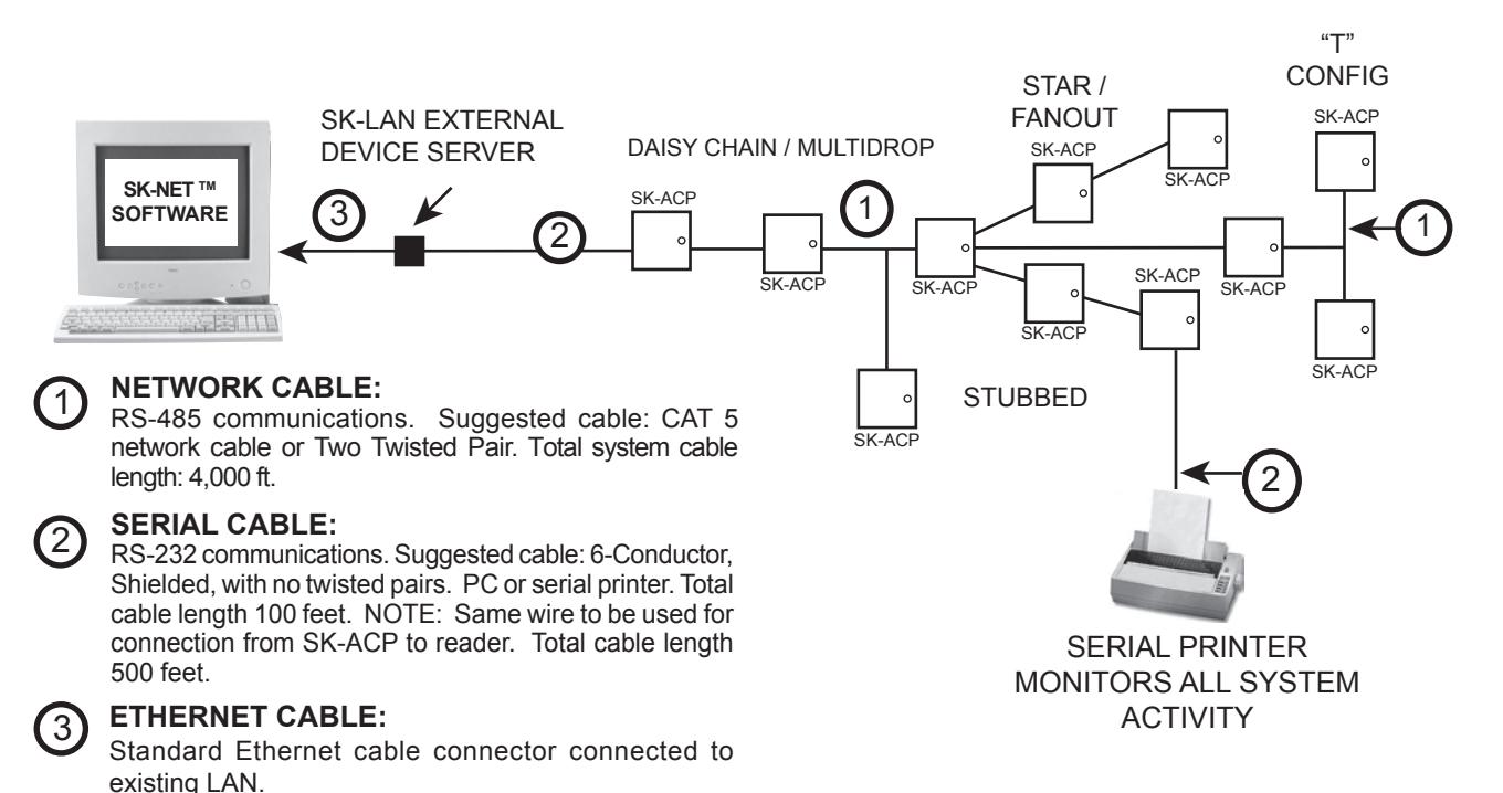
NOTE: Each SK-ACP above can support 2 Wiegand output card readers.
APPENDIX B
SK-NETTM EQUIPMENT COMPONENTS & SPECIFICATIONS
SK-ACP:
Two Door Access Control Unit
RK-WM: or RK-WS or RK-WL
Proximity Reader (2 per SK-ACP)
RKCM-02 Molded Proximity Cards Specify Quantity
or RKKT-02 Key Tags or RKCI-02 ISO Image-able cards
ET4-WXM, ET4-WXS, ET8-RO-W-D, or ET8-RO-W-M
Contactless Smart Card Reader (2 per SK-ACP)
ET-CI ISO Image-able Contactless Smart Cards Specify Quantity
or ETST Key Tags
SOFTWARE
SK-NET™ — Basic Software SK-NET™ -MLD — Multi-Location Dial-Up Software SK-NET™ -MLD — C/S 2, 5,10,15 Client/Server Software for Multiple Workstations
ACCESSORIES:
NET-CONV-P — RS-232 to RS-485 Converter with Power Supply - one required per system (unless using a gateway connection)
CBLSA — Demo Cable & Connectors For Bench Testing or field connection with a laptop
SK-MDM — Modem - 56K Baud External Modem for dial-up connection to any SK-ACP with MLD software
SK-Plug 9 — Computer connector (DB9) with wire pigtail.
SK-ACP-PS — Transformer and stand by battery for SK-ACP.
SK-LAN — External Device Server for TCP/IP connection using SK-NET-MLD Software
SPECIFICATIONS
| PHYSICAL | Depth 3.0" Width 10.0" Height 11.0" Weight 68.8 c |
(7.62 cm)
(25.40 cm) (27.94 cm) oz. (1.95 kg) g Material is All Steel; Color is Beige |
|||
|---|---|---|---|---|---|
| POWER REQUIREMENTS Power Supply Sold Separately | 16.5-24 VAC, 20 VA or 16-30 VDC, 500 mA (DC POWER IS RECOMMENDED). If SK-LAN-MOD or SK-WLS-MOD network modules are used a 24 VDC 1Amp supply is required. If RK-WL readers are used, recommend a 24 VDC 1.5 Amp supply. A 12 VDC Power Supply may be used if connected to Battery Back-Up Leads. | ||||
| BACK-UP BATTERY | 12 V, 1.2 - 6 Ah (Optional, Sold Separately) | ||||
| CARD READERS | Connect two card readers with two-line Wiegand output, up to 40 bits. Provides 14 VDC, 400 mA max. power for each card reader. | ||||
| SOFTWARE | SK-NET™ Software Version | 2.0 or greater | |||
| OUTPUTS - 2 Per Door (Total of 4) |
Latch & Alarm Shunt
Auxiliary |
DPDT contact, 5A, up to 250 VAC or 30 VDC
DPDT contact, 2A, up to 220 VAC or 30 VDC |
|||
|
INPUTS - 2 Per Door (Total of 4)
Auxiliary 2 |
Auxiliary 1 |
Requires SPST contact closure
Requires SPST contact closure |
|||
| COMMUNICATION |
RS-232
RS-485 Wiegand Input (2) Modem Printer |
5-Wire Shielded Cable, up to 38.4K baud, full duplex, (8N1) Single Twisted Pair, shielded cable with a signal ground Programmable up to 40 bits 14 VDC @ 400 mA supplied to each reader, Requires Hayes compatible - 1.2 to 38.4k baud Serial Printer (or Parallel printer with serial converter) | |||
|
ENVIRONMENT
Humidity |
Ambient Temperature |
-40° F to 158° F (-40° C to 70° C)
0% to 95% relative humidity (non-condensing) |
|||
| OPERATIONAL |
Card Capacity
Time Zones |
65,535/Door (Highest card number = 65,535) 15 for card access, one door unlock; full week plus holiday in one-half hour segments; 32 programmable holidays; selectable automatic daylight saving time. | |||
| Per Door |
Facility Code
Latch/Alarm Shunt Timer Antipassback Auxiliary Inputs (2) |
Up to 16 different codes simultaneously (max. # of cards 65,535) Programmable from 1/4 to 30 seconds Real or Timed (1 to 30 minutes); hard or soft Programmable for door monitor, tamper monitor, remote open, remote inactive, bell, arming circuit or user defined | |||
| ( | Auxiliary Output (1) Limited Use Cards | Output is programmable to activate under one of many possible alarm conditions, time zone or card violations. 4,000 (in a block within 65,535) programmable from 1-500 uses, days, weeks or number of days after first use. | |||
|
Transaction Storage
Memory |
4,864 events
Non-volatile |
||||
This product complies with UL 294 Standards, CE (European Standards), and with Part 15 of Class B FCC Rules.
APPENDIX C
CONNECTING A MODEM TO SK-ACP
The SK-MDM (U.S. Robotics) has been preconfigured to work with Secura Key access control systems and SK-NET-MLD software. (NOTE: SK-NET-DM and the free download version of SK-NET™ do not support modem connections.) NOTE: This modem requires version 3.0 or later of SK-NET-MLD software.
- 1. Plug the telephone cable provided into the SK-MDM and into the jack for a dedicated phone line.
- 2. Plug the serial cable (provided) into the DB25 outlet on the SK-MDM.
- 3. Connect the serial cable wires to the J-7 connector on the SK-ACP.
| PANEL |
WIRE
COLOR |
DB25 |
|---|---|---|
| 1 | BLACK | 7 |
| 2 | WHITE | 3 |
| 3 | RED | 8 |
| 4 | GREEN | 4 |
| 5 | ORANGE | 2 |
- 4. Connect the modem power supply to the SK-MDM and plug into a 110VAC wall outlet.
- 5. For added protection, the modem power lines, the phone line connection and the serial connection may be connected to suitable surge suppressors.
- 6. Establish connection from the computer to the access control system using SK-NET-MLD software. (Follow instructions in the SK-NET™ manual.)
REMOTE SITE MODEM CONFIGURATION WITH SK-ACP
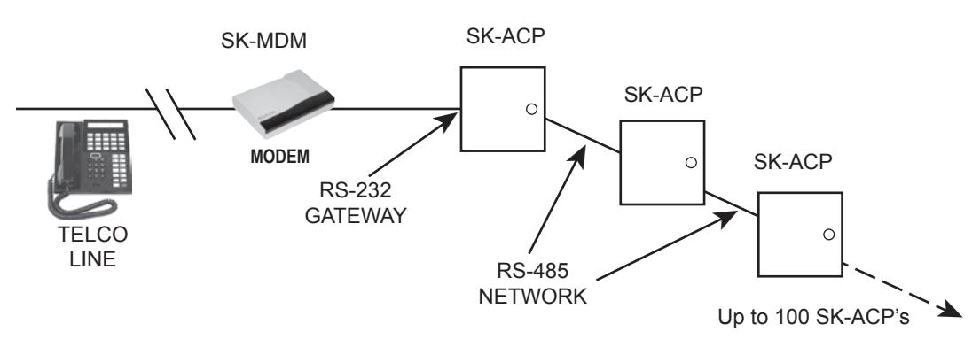
Warranty: While Secura Key will be happy to help with modem-related problems, for best results contact a U.S. Robotics Service Center. To locate a convenient Service Center, go to www.usr.com. U.S. Robotics warrants this product for two years (detailed warranty is enclosed with the modem).
APPENDIX D
CONNECTING AN SK-ACP TO A LOCAL AREA NETWORK
The SK-LAN External Device Server can be used with the Secura Key SK-ACP to connect to a local area network.
Alternately, you can use either the SK-LAN-MOD Network Module (which connects to a network jack), or the SK-WLS-MOD Wireless Network Module (which connects with an 802.11 wireless network.) These units plug into connector J9 on the SK-ACP, and they receive their power from the panel. You must remove the 2-pin jumper from J9 before installing either module.
Refer to the Install/Setup documentation provided with the SK-LAN, SK-LAN-MOD or the SK-WLS-MOD for details on connections, IP addressing, setup and testing your network connection.
To configure your system using SK-NET-MLD software, see SK-NET™ Manual Section 2 for instructions.
NOTES:
- 1) Always close SK-NET™ before closing WINDOWS® to avoid LAN communications failures.
- 2) The manufacturer's instruction manual is included with the SK-LAN. Keep this document for additional troubleshooting and setup information.
| PANEL |
WIRE
COLOR |
DB 25 |
|---|---|---|
| 1 | BLACK | 7 |
| 2 | WHITE | 3 |
| 3 | RED | 8 |
| 4 | GREEN | 4 |
| 5 | ORANGE | 2 |
APPENDIX E
SK-ACP TROUBLESHOOTING GUIDE
1.1 Cards do not work when creating a new Access Group
- 1. Did you drag-and-drop readers into the new Access Group?
- a. From the Explorer screen, click on All Readers.
- b. Drag-and-drop readers from the right side of the screen into the new Access Group.
- c. Click on the "+" sign next to the new Access Group to view the readers in the new group.
- d. Perform a Card Send, as described below.
- 2. Did you send the cards to the Location?
- a. Click on "Send Users Full".
1.2 New Transactions are not appearing in the Transaction Screen
-
1. Are transactions being filtered?
- a. From the Transaction screen, click on the Filter icon.
- b. Click on Defaults. Click OK.
-
2. Are you logged in to the Location?
- a. From the Explorer screen, open the All Readers folder to display reader icon(s). Are there Green check marks by each reader icon?
- b. If readers do not have Green check marks (or have red lines through them), is there a Red arrow next to the Location icon?
- c. If there is a Red arrow, but readers are not logged in, click on the Log-In icon on the toolbar.
- d. If there is not a Red arrow or a Green check mark, click on the location name, click on the Connect icon on the toolbar.
- 3. Have you excluded any transactions?
-
a. Right click on All Readers.
- b. Click on the Transactions tab.
- c. View Transaction Types. If there is a check mark in the box located next to a Transaction Type, it will not be sent to your Transaction database in SK-NET™.
1.3 "Invalid Facility Code" message when using newly-added cards
-
1. Do the new cards have a different Facility Code than the previous ones?
- a. Go to one of the SK-ACP panels. Take a sample card with each different facility code. Press the reset button.
- b. Present a sample card with each Facility Code to one of the readers attached to the SK-ACP while the LED is flashing Red and Green.
- c. Repeat this process for each SK-ACP. You can also send Facility codes to all panels through SK-NET™, like this:
- d. From the Explorer screen, right click on the name of the reader that has the new Facility Code.
- e. Select Properties.
- f. Click on the Service tab. You should see the quantity of Facility Codes active in that panel.
- g. Under Facility Codes (Panel) click Edit.
- h. Click Close.
- i. Click Send To All.
- j. Click Close.
- k. After all cards are working, right click on All Readers.
- l. Select Backup. Select All Readers.
1.4 Reader does not read-LED is Flashing Red or Green
A slowly flashing Red LED indicates that the reader is in the Inactive mode. A slowly flashing Green LED indicates that the reader is in the Unlocked mode. These conditions exist when someone has activated a Door Control, from SK-NET,™ or when an input is shorted and programmed Remote Inactive or Remote Open. A flashing green LED also indicates the door has been unlocked by the Door Schedule. To check the door status:
- 1. From the Explorer screen, right-click on the name of the reader.
- 2. Select Properties.
- 3. Click on the Door Controls tab.
- 4. What is the Current Door State? This will help identify why the reader is in the Inactive or Unlocked mode.
- 5. Click on Normal if the reader shows Inactive Lock or Inactive Unlocked. This will change the Current Door State to Active Normal.
- 6. Unlock via Door Schedule indicates the door is unlocked by the schedule. To disable the schedule click on Edit, click in the Disabled box and Send.
1.5 Lost Communications between PC and Readers
-
1. Check Com Settings
- a. From the Explorer screen, right click on the Location Name.
- b. Select Properties.
- c. Click on the Connection Tab.
- d. Run the Connection Wizard.
-
e. If the Wizard finds the connection, click OK and then Connect. If not, select your connection below.
- 1. RS-232 direct connect, computer COM port to the SK-ACP COM port. (See Section 1.6.)
- 2. RS-232 to RS485 converter, computer to converter to the SK-ACP. (See Section 1.7.)
- 3. TCP/IP connection via LAN, WAN. Contact the IT department.
- 4. Modem connection, must have Local Connect unchecked and modem phone number provided. Try to repower the modem and SK-ACP.
2. Login Failure
- a. In the Explorer screen, look for a red arrow next to the Location icon. This indicates you are connected to the Location.
- b. Click on the "+" next to All Readers. If the reader shows a green check mark indicates the reader is logged in. An icon with a red "X" indicates lost communications with that reader. If this occurs, perform a Power Reset. (See Section 1.8)
1.6 Using RS-232 Voltage Measurements to Check Communication Problems
If you cannot connect, it will be necessary to take voltage measurements to identify whether the problem is with the SK-ACP or with the computer.
RS-232 Direct Connection
- 1. From the Explorer screen, right-click on the Location.
- 2. Select Properties.
- 3. Click on the Connection tab.
- 4. Uncheck the box next to "Gateway (RS-232)"
- 5. Click on the Connect button.
The system will fail to connect, but in the process it will open the computer COM port, making a voltage test possible.
1. Voltages: Measure voltages at the gateway reader's terminal block, communications pins 1 to 5.
Connect the ground lead to pin 1 (logic ground) for all measurements.
- a) Pin 2 (Receive Data, RXD). The voltage should read between -5 VDC to -12 VDC. This voltage comes from the PC. If the voltage is wrong or missing, disconnect the reader from the PC, and measure the voltages at the reader (should be 0.0 VDC) and at the PC (should be between -5 VDC to -12 VDC).
- b) Pin 3 (Clear to Send, CTS). The voltage should read between +5 VDC to +12 VDC. This voltage comes from the PC. If the voltage is wrong or missing, disconnect the reader from the PC, and measure the voltages at the reader (should be 0.0 VDC) and at the PC (should be between +5 VDC to +12 VDC).
- c) Pin 4 (Request to Send, RTS). The voltage should read between -5 VDC to -12 VDC. This voltage comes from the Card Reader. If the voltage is wrong or missing, disconnect the reader from the PC, and measure the voltages at the reader (should be -9.5 VDC) and at the PC (should be 0.0 VDC).
- d) Pin 5 (Transmit Data, TXD). The voltage should read between -5 VDC to -12 VDC. This voltage comes from the Card Reader. If the voltage is wrong or missing, disconnect the reader from the PC, and measure the voltages at the reader (should be -9.5 VDC) and at the PC (should be 0.0 VDC).
After testing voltages, return to the Location/Properties/Connection box and re-check the box next to "Gateway (RS-232)".
1.7 NET-CONV Converter Connection
If you cannot connect and you are connected using the NET-CONV converter, test voltages as follows:
- 1. Measure input voltage from the converter power supply. It should be between 9 VDC and 16 VDC.
- 2. Measure voltage between Ground (minus side of power supply) and TD (A). It should be 0 VDC.
- 3. Measure voltage between Ground (minus side of power supply) and TD (B). It should be between 2.5 VDC and 5 VDC.
If these voltages are incorrect, contact Secura Key Technical Support.
1.8 Power Reset
Occasionally it may become necessary to perform a power reset on a 28SA-PLUS or SK-ACP panel. (For example, after a power surge.) This procedure will reset the node address, requiring a recovery procedure in SK-NET™.
To perform a Power Reset:
- 1. Disconnect power from the reader or panel (including any backup battery)
- 2. Hold down the reset button.
- 3. While holding the reset button, restore power. Continue holding the button for two seconds.
To clone the readers:
- 1. From the Explorer screen, right click on the Location Name.
- 2. Select New.
- 3. Select Readers.
- 4. Select Quick Find ( with less than 20 readers), or Search if (with more than 20 readers).
- 5. SK-NET™ will find the original reader(s) as new ones.
- 6. Click OK to bring them into the system. Do not log in at this time.
- 7. Look under All Readers and you will notice that you now have duplicate reader(s) names. The old one will still have the red X through the icon, and the new one will not.
- 8. Drag and drop the New reader(s) on to the old reader(s) with the same name. You will be asked to Replace the reader, click Yes. This will clone the original reader settings in to the New reader.
- 9. Right click on All Readers and select Login. Now all the readers should have a green check next to each reader.
1.9 Replacing an SK-ACP
NOTE: There are no changes required in SK-NET™ when replacing a card reader connected to the SK-ACP
While replacing the SK-ACP it is recommended that you note the serial number of the board being replaced along with the new board being used for the replacement. This will simplify the following steps used in this procedure.
Note: DO NOT delete any readers from the Explorer screen!
After completing the replacement of the board you need to start SK-NET™, connect and login. Click on the + next to All Readers and you will notice a red X through the reader(s) icon(s) which have been replaced.
- 1. Left click on All Readers, now it will be highlighted.
- 2. At the top of the Explorer screen click on Explorer.
- 3. Select View.
- 4. Select Details. Notice that on the right hand side of the Explorer screen all of the readers are listed along with the Node ID, Logged In, Serial Number, Version, and Type.
- 5. Right click on All Readers.
- 6. Select New, Readers, Quick Find (for less than 20 readers) or Search (for more than 20 readers).
- 7. After SK-NET™ finds the new readers, click OK to add them to the system (note that under All Readers the new readers found show the serial number as the name of the reader). Do not login.
- 8. Look at the serial number or name of the new reader(s) and drag and drop the new one over the old one with the red X through the icon (be sure to include the "–1" or "–2" as part of the serial number).
- 9. When asked 'Do you wish to replace the reader?' Answer YES. SK-NET™ now will use the data files from the old reader and program them in to the new reader including sending cards.
- 10. Repeat steps 8 and 9 for all readers being replaced.
- 11. Test a card or two, the replacement is now complete.
Windows® 95/98/XP Hyper Terminal Setup*
In order to connect to an SK-ACP access control panel using only Windows®, follow these steps:
- 1. Click on the start button on the lower left corner of the screen.
- 2. Select Programs.
- 3. Select Accessories. (For XP select Communications next)
- 4. Select Hyper Terminal.
- 5. Double click on Hyperterm.
- 6. Type Secura Key in the name field. (For XP select an icon)
- 7. Click OK.
- 8. The next window will have a selection at the bottom of "Connect Using". Be sure it is set to "Direct to Com1", or whatever com port is available. (For XP - click OK)
- 9. Click the settings tab at the top of the box.
- 10. Under Emulation, select VT100. (For XP skip to Step 12).
- 11. Click OK.
-
12. Verify the following setting in the next properties box:
- Bits per second: 38,400 •
- Data bits: 8 •
- Parity : None (XP only) •
- Stop bits: 1 •
- Flow control: None •
- 13. Click OK.
- 14. The next box should display the greeting and the "Enter Password" prompt. Enter 12345, or the appropriate password.
- 15. If this greeting does not appear, press the Enter or Return key once.
- 16. If the greeting still does not appear, check the wiring between the unit and the PC and test the com port.
- 17. To exit, click the (X) box on the upper right. Be sure to answer Yes to save the session.
Obtain the technical bulletin "Programming an SK-ACP Using a Terminal Program" from www.securakey.com.
* Hyper Terminal is not available on Windows® Vista. Third party equivalent programs are available on the internet.
System Architecture:
MULTI-READER SYSTEMS:
- Network is twisted-pair, shielded cable
- Maximum total system cable length, 4000 feet (1219.2 m)
- PC connects to Network using RS-232/485 converter, Model NET-CONV-P; Direct Connect by using the RS-232 port on any reader or panel, or via TCP/IP using SK-LAN.
- PC also can connect to remote locations with multiple reader, via modem
- See Diagram for System Configurations
Software upgrades can be downloaded from www.securakey.com
SINGLE READER SYSTEM:
PC connects directly to reader or panel via RS-232 or remotely via modem
SK-NET™ REQUIREMENTS
- CD-ROM Drive (unless software is downloaded)
- High-speed RS-232 COM Port (38.4k baud rate) or TCP/IP
- Modem if you use dial-up
- 16 bit color video card or better
- Printer for reports
| DECOM | MENDED | FOR LARGER | CVCTEMC |
|---|---|---|---|
| RECUM | MENDED | FUK LAKUEN | STOLEMO |
CD-R or equivalent for system backup
| MINIMUM REQUIREMENTS* | |||||
|---|---|---|---|---|---|
| OPERATING SYSTEM |
PROCESSOR
SPEED |
RAM |
AVAILABLE
DISK SPACE |
||
| WINDOWS® XP (32 bit) | 1 GHz | 1 GB | 1 GB | ||
| WINDOWS® VISTA (32 bit) | 1 GHz | 1 GB | 1 GB | ||
| * For larger installation more disk space may be required. | |||||
| RECOMMENDED SYSTEM | |||||
| WINDOWS® XP | 2 GHz | 2 GB | 10 GB | ||
| WINDOWS® VISTA | 2 GHz | 2 GB | 10 GB | ||
| If using Vista, Aero-capable discrete graphics card with 128 MB Graphics Memory. | |||||
| SERVER REQUIREMENT** | |||||
|
WINDOWS® 2000
OR GREATER |
2 GHz | 1 GB | 1 GB | ||
| ** For SK-NET-MLD-C/S version, a server is required. | |||||
APPENDIX F
PREVENTING LIGHTNING DAMAGE
SURGE PROTECTION FOR ACCESS CONTROL SYSTEMS
Access Control equipment is susceptible to damage from lightning, especially when installed outdoors. Voltage spikes which travel through buried data cables, telephone lines or AC power lines can damage Access Control equipment indoors, as well.
While nothing can protect equipment from a direct lightning hit, surge protectors can help to minimize the damage caused by nearby lightning strikes. Surge protectors operate by connecting Transorbs or Varistors from data lines to ground. Surge protectors have no effect on normal circuit voltages, but can act quickly to divert large voltage spikes to ground and away from sensitive components.
All Secura Key equipment includes on-board surge suppresion, but properly grounded off-board devices will provide the best protection.
Where to Install Surge Protection
- On the AC line voltage input to the PC. (A UPS with surge protection is recommended).
- On the AC line voltage input to any transformer or DC Power Supply connected to an SK-ACP or Modem.
- On RS-485 data lines connecting an SK-ACP to a PC, Printer or Modem, using a NET-CONV-P converter.
- On RS-232 data lines from SK-ACPs to PCs, Printers or Modems.
- On Telephone lines connected to Modems.
- On Data lines connecting card readers or keypads to the SK-ACPs.
Protect Both Ends of Data Lines
Surge Protectors should be installed at both ends of all Data Lines.
Wire Distance from the Surge Protector
You must locate the protector at least three wire feet away from the device being protected. The additional wire resistance will dissipate the energy from leading edge of the spike. The wire can be coiled; a three-foot physical distance is not required.
Grounding the Surge Protector
Surge protectors must be connected to a verified good, nearby earth ground. This can be AC Power Ground, a 10' Copper Ground Stake, or Building Ground. Run 16 AWG or heavier wire as short a distance as possible, and avoid any bends in the wire.
Self-grounding Surge Protectors
Do not use surge protectors unless they are equipped with a separate ground wire or ground screw. Self-grounding Surge Protectors use the connector shell or Pin 1 as a ground path; however, the shell and Pin 1 are not always grounded.
AC Power Surge Protectors
AC Power Surge Protectors must be plugged into a properly grounded 3-wire socket. If a 3-wire socket is not available, have one installed by an electrician; do not use a 2-prong socket by cutting off the 3rd prong on the plug, or by using a 3/2 converter, or the surge protector will be rendered useless.
Terminating Cable Shields
Connect cable shields on data cables at one end only. You may terminate the cable shield to the same ground as the surge protector. Leave the cable shield unconnected at the opposite end.
Surge Protectors
There are many manufacturers of surge protectors. Some are designed to protect a single type of circuit such as high voltage AC, low voltage DC or telephone lines. Secura Key offers two multifunction surge suppressors that are well-suited to protecting access control equipment. The DTK-XR is a good choice for protecting an SK-ACP panel from power, data and telephone line surges. If the card readers or keypads attached to the SK-ACP are located outdoors you may also wish to install DTK-CR protectors on each reader circuit. Wiring instructions for these surge protectors appears on the following pages.
More Information
For more information on lightning, including additional lightning protection methods and a US lightning density map, see Secura Key Applications Bulletin #28 on our website. (www.securakey.com)
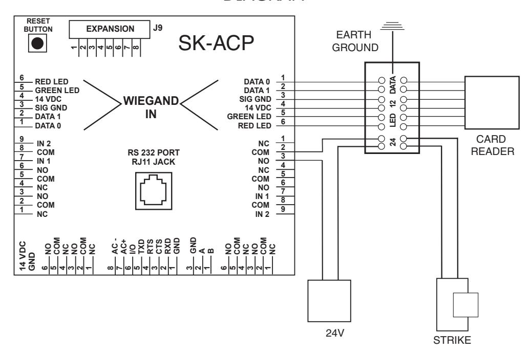
CONNECTING THE DTK-CR (READER PROTECTION)
The DTK-CR is a multi-line surge suppressor that can protect card readers and keypads from damaging power surges. It can be used between an SK-ACP panel and any wiegand-output reader/keypad. This is especially useful where readers are located on gates and parking control equipment. It may also be used to protect standalone access control units.
Locate the DTK-CR at least three (3) feet of wire from the unit to be protected.
Connect the green ground wire to a dependable earth ground, using a heavy gauge cable (12 or 14 AWG recommended). Keep the wire run to the grounding location as short as possible.
Wiegand-output Card Readers and Keypads
Connect the wiegand "0" and wiegand "1" wires from the control panel to DATA IN. Connect the wiegand "0" and "1" wires from the reader to DATA OUT.
Connect the reader power lines from the control panel to 5-12V IN. Connect the power wires from the reader to 5-12V OUT.
Connect the "red" LED and "green" LED lines from the control panel to LED IN. Connect the "red" and "green" LED lines from the reader to LED OUT.
If you are operating a 24 volt electric lock or strike, you can protect it also by connecting the lock power lines to 24V IN and OUT.
DTK-CR DIAGRAM
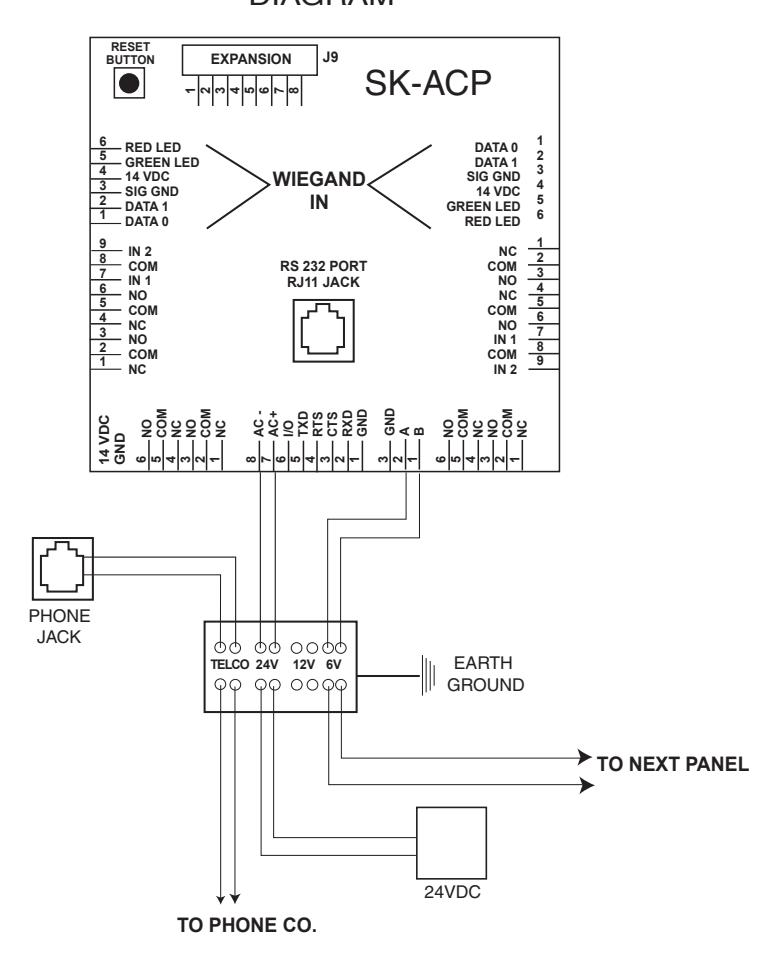
CONNECTING THE DTK-XR (DATA LINE PROTECTION)
The DTK-XR is a multi-line surge suppressor that can protect an SK-ACP control panel, 28SA-PLUS or other access control unit from damaging power surges.
Locate the DTK-XR with at least three (3) feet of wire from the unit to be protected.
Connect the green ground wire to a dependable earth ground, using a heavy gauge cable (12 or 14 AWG recommended). Keep the wire run to the grounding location as short as possible.
If you are using 24 volts to power the access control unit (recommended) connect the power supply to 24V IN and connect the access control unit to 24V OUT. If you are using 12 volts to power the access control unit, connect the power supply to 12V IN and connect the access control unit to 12V OUT.
If the access control unit is connected to other units via RS-485 (i.e. 28SA-PLUS or SK-ACP) you may connect the "A" and "B" lines of the RS-485 twisted pair to 6V IN and 6V OUT.
If you are using a dial-up modem, you may protect the modem by running the "Tip" (usually green) and "Ring" (usually red) phone lines to TELCO IN and connect the phone jack to TELCO OUT.
DTK-XR DIAGRAM
WARRANTY (U.S. and Canadian)
"This product is warranted against defects in materials and workmanship for a period of 2 years from the date of purchase.. Secura Key shall, at its option, either replace or repair this product, if returned to us freight prepaid within the warranty period. This warranty does not include freight, taxes, duties, or installation expenses. THE WARRANTY SET FORTH ABOVE IS EXCLUSIVE AND NO OTHER WARRANTY, WHETHER WRITTEN OR ORAL, IS EXPRESSED OR IMPLIED. SECURA KEY SPECIFICALLY DISCLAIMS ANY IMPLIED WARRANTIES OR MERCHANTABILITY AND FITNESS FOR A PARTICULAR PURPOSE. The remedies provided herein are the buyers' sole and exclusive remedies. In no event shall Secura Key be liable for direct, indirect, special, incidental or consequential damages (including loss of profits), whether based on contract, tort or any other legal theory." Contact Secura Key for Card/Tag and Export Warranty Policies.
WARNING:
INSTRUCTION TO THE USER
This equipment has been tested and found to comply with the limits for a class B digital device, pursuant to part 15 of the FCC Rules. These limits are designed to provide reasonable protection against harmful interference in a residential installation. This equipment generates, uses and can radiate radio frequency energy and if not installed and used in accordance with the instructions, may cause harmful interference to radio communications. However, there is no guarantee that interference will not occur in a particular installation. If this equipment does cause harmful interference to radio or television reception, which can be determined by turning the equipment off and on, the use is encouraged to try to correct the interference by one or more or the following measures:
- Reorient or relocate the receiving antenna.
- Increase the separation between the equipment and receiver.
- Connect the equipment into an outlet of a circuit different from that to which the receiver is connected.
- Consult the dealer or an experienced radio/TV technician for help.
This equipment has been certified to comply with the limits for a class B computing device, pursuant to FCC Rules. In order to maintain compliance with FCC regulations, shielded cables must be used with this equipment. Operation with non-approved equipment or unshielded cables is likely to result in interference to radio and TV reception. The user is cautioned that changes and modifications made to the equipment without the approval of the manufacturer could void the user's authority to operate this equipment.

20301 Nordhoff Street • Chatsworth, CA 91311 Phone: 818-882-0020 • Fax: 818-882-7052
TOLL FREE: 800-891-0020
E-mail: mail@securakey.com • Web site: www.securakey.com