Securakey RKDT-SA-M SA-S Manual
Open the original PDF document
View PDFRadio Key®
RKDT-SA-M and RKDT-SA-S
Stand Alone • Dual Technology Proximity Access Control System
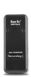
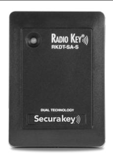
Operating Guide
COPYRIGHT © 2010 SOUNDCRAFT, INC. 3322246 7469
Radio Key® RKDT-SA-M / RKDT-SA-S Operating Guide
Table of Contents
| Introduction1 | |
|---|---|
|
Ordering Cards or Key Tags
4 |
|
| Programming Radio Key® RKDT-SA-M/SA-S6 | |
| Handheld Programmer (RK-HHP)7 | |
|
Programming Steps
8 |
|
| Basic Operation23 | |
|
Warranty
24 |
|
|
Specifications
25 |
|
| Illustrations | |
| Figure 1, Radio Key® RKDT-SA-M/SA-S Units2 | |
| Figure 2, Hand-Held Programmer3 | |
| Figure 3, Radio Key® Cards and Key Tags5 | |

INTRODUCTION
The Radio Key® RKDT-SA-M/SA-S is a programmable single-door proximity access control system which controls access for up to 65,000 users. It can control an electric strike, magnetic lock, or gate operator, and has an additional programmable input which may be set as a remote open input or as an LED control for use with the Wiegand output. A Wiegand output is also provided to allow for later upgrading to an on line system. Information on using the RKDT-SA-M/SA-S as a Wiegand reader is contained on page 21. The major components are shown in Figures 1, 2 and 3.
The Radio Key® RKDT-SA-M/SA-S Access Control Unit contains the CPU, memory, access relay, and an internal proximity reader. It has a beeper, and a bi-color LED indicator. An RK-HHP Handheld Programmer (not included), is used to add or delete cards or tags, to set the operating mode, to program the password and latch timer. The Radio Key® RKDT-SA-M/SA-S is compatible with the Secura Key SecuRelay™, an intelligent relay module used to eliminate the possibility of break-in by attacking the access control unit.
The RKDT-SA-M/SA-S is a dual-technology reader which can read Secura Key's Radio Key® proximity cards or key tags, as well as HID® 26-bit proximity cards in the standalone mode. In Wiegand mode, the RKDT-SA-M/SA-S can read most HID® proximity cards up to 37 bits. The RKDT-SA-M/SA-S does not read HID® Active Cards (1351L) or iClass® cards.
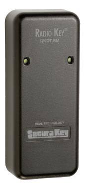
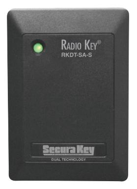
Figure 1 - Radio Key ® RKDT-SA-M/SA-S
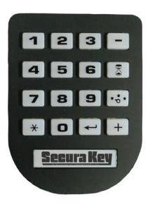
Figure 2 - Hand-Held Programmer (RK-HHP)
Ordering Cards or tags
The Radio Key® RKDT-SA-M/SA-S works with Secura Key RKCM-02 molded (clamshell) cards, RKCI-02 ISO-standard cards and RKKT-02 key tags. Card Format 303 (32-bit) and Format 201(26-bit) can be used. Radio Key® RKDT-SA-M/SA-S also works with HID® 26-bit proximity key tags and passive cards. It may also work with other HID® proximity Wiegand formats, but it is recommended to contact the factory to be sure.
When you order Format 303 cards or tags for a new project you will be assigned a new Facility Code and your cards or tags will begin with ID number 1. As you need additional cards or tags you can order the same Facility Code, specifying the starting number, which will be one digit higher than your highest existing card or tag.
The RKDT-SA-M/SA-S can learn up to 10 different Facility Codes. If it becomes necessary to mix cards or tags with more than one Facility Code in the same reader (or if you are combining Radio Key® and HID cards), be sure that the card ID numbers are not duplicated. When learning facility codes, the RKDT-SA-M/SA-S will distinguish between HID and Radio Key® proximity cards. This increases security by only allowing access to the exact card type presented. If you are combining HID and Radio Key®
cards with the same facility code, be sure to present one of each type to the reader when entering facility codes.
NOTE: RKxx-01 cards or key tags will not work for the RKDT-SA-M/SA-S. The LED will flash amber to let you know it is the wrong type of card.
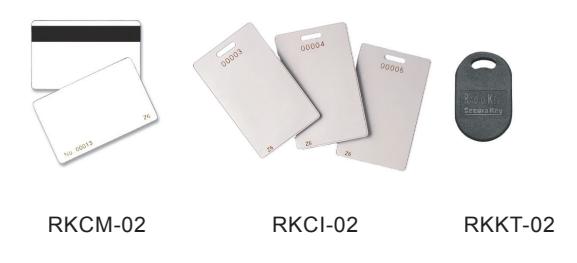
Figure 3 - Radio Key® Cards and Key Tags
PROGRAMMING RADIO KEY® RKDT-SA-M/SA-S
When the RKDT-SA-M/SA-S is first powered up, the LED will be flashing Red and Green. Present a card to the unit to set the Facility Code and the flashing will end in approximately 10 seconds.
Radio Key® cards or tags are pre-encoded and engraved at the factory with a Facility (Site) Code and an individual card ID number.
You must teach the RKDT-SA-M/SA-S which Facility Code or Codes (up to 10) it should recognize. You must also enroll the card ID numbers that will be Valid. The Radio Key® cards and tags are sequentially numbered, so you can validate a block of ID numbers.
Be sure to make a record of each person who is issued a card or tag along with the ID number of their card or tag. Use the Log Sheet supplied with the reader as a photo copy master.
Use the same procedure when teaching the RKDT-SA-M/SA-S facility codes from HID® 26-bit cards.
The RK-HHP Handheld Programmer
Note: The RK-HHP required to program the reader. One RK-HHP may be used on several readers.
The RK-HHP has 16 keys:
| ENTER | "7" | SEVEN | |
|---|---|---|---|
| "0" | ZERO | "8" | EIGHT |
| "1" | ONE | "9" | NINE |
| "2" | TWO |
"
" |
THRU |
| "3" | THREE |
"
" |
VALID |
| "4" | FOUR |
"
" |
VOID |
| "5" | FIVE | SET TIMER | |
| "6" | SIX | MODE | |
Program the unit by pressing these keys and holding the RK-HHP near the RKDT-SA-M/SA-S. As you press keys the unit will chirp to indicate that it has received the command. The next sections of this manual explain the programming sequences used to perform the various program functions.
PROGRAMMING STEPS
To program the Radio Key® RKDT-SA-M/SA-S, you must first enter the program mode as described in the next section below. Once in the program mode, the LED will blink amber as an indicator. To take the unit out of program mode you may select an operating mode (see page 17) or simply allow 15 seconds to elapse without presenting a program card to the reader.
After you have completed a proper program sequence, the unit will beep and the LED will flash green to indicate that the program instruction has been accepted. A red light and a beep at the end of a programming sequence means that you have made an error. Refer to the appropriate section, and carefully re-enter the command in the proper sequence.
NOTE: Card ID Number and other values in the following examples are for demonstration purposes only; enter the appropriate values for your system.
To Enter Program Mode:
Using your programmer, enter your password and then press "ENTER". (All new units are pre-programmed with the
password 12345.) The LED will flash amber to show that the unit is in Program Mode. The unit will "time out" and return to Active (Normal) Mode in 15 seconds if no programming follows.
(Password) (ENTER) 1 + 2 + 3 + 4 + 5 +
NOTE: If five incorrect passwords are entered, the unit will sound an alarm and display a red LED for 30 seconds, then return to normal mode.
Change your Password:
Put the unit into the Program mode, if necessary (see above). Press THRU. Then enter the desired new password (exactly 5 digits). Then press THRU again. Repeat the new password. Press ENTER. A green light and beep means that the Password was changed. Note that 12345 is the default (factory) password; use another number sequence for best security.
(New Password - 54321) (Re-type New Password - 54321) (ENTER) (THRU) (THRU) + 5 + 4 + 3 + 2 + 1 + + 5 + 4 + 3 + 2 + 1 +
Lost or forgotten Password
If the password is lost or forgotten, it can be restored to the factory default (12345). Remove the Radio Key® RKDT-SA-M/SA-S unit from the wall and disconnect power. With the Data 1 line (white wire) temporarily connected to the Remote open line (brown wire), restore power. The factory default (12345) is now in effect. The LED will flash alternately Red and Green. While this is occurring, set the Facility Code or Codes in the reader (see below). Remove power and reconnect the unit for operation, restore power and remount the unit. This procedure will NOT delete any cards or tags from reader's memory.
Restore All Default Settings
To reset all Factory Defaults and clear the reader memory of all cards, put the unit in Program Mode, then press the "THRU" key two times, press "9" two times, then press ENTER.
Setting Facility Code(s)
Before any cards are added to the RKDT-SA-M/SA-S you must set the Facility Code or Codes. When a new reader is first powered up the LED should be flashing alternately Red and Green. This indicates that the unit is in the "Learn Facility Code" mode. You can also place a reader in this mode by entering
the Program Mode (see page 9) then pressing Mode followed by "9" followed by Enter.
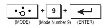
While the LED is flashing Red/Green present one User Card for each Facility Code being used to the reader, one at a time. After you are finished, allow the reader to time out and return to the Normal Mode before proceeding. NOTE : An invalid facility code will beep with no LED visible.
If it becomes necessary to mix cards or tags with more than one facility code in the same reader, and/or if you combine Radio Key® and HID® cards or tags, be sure that the Card ID numbers are not duplicated.
Setting Additional Facility Codes
It is also possible to add a new facility code to the reader without reentering all the existing facility codes, provided that the reader has less than the maximum number (10) of facility codes stored.
To enter this mode, first enter Programming Mode (page 9) then press Mode, followed by 1, then 0 followed by Enter.
(MODE) (Mode Number 10) (ENTER) + 1 + 0 +
While the LED is flashing Red/Green, present a user card for each of the facility codes(s) you want to add. After you are finished, allow the reader to time out and return to normal mode before proceeding.
ADDING AND DELETING USERS
Add A Key Tag or Card To The System
Place the unit in the Program Mode (See Page 9). Press Add, followed by the card or tag ID number. Then press Enter. For example, to add card number 12 to the reader the following sequence would be used:
(ADD) (User ID Number 12) (ENTER) + 1 + 2 +
Card number 12 is now valid.
Add A Series Of Cards or Tags To The System
Place the unit into the Program mode (see Page 9). Press Add, followed by the lowest card ID number. Then press Thru, followed by the highest card ID number. Then press Enter. For example, to add card number 1 through 10 to the system:
Card numbers 1 through 10 are now valid.
Delete A Card or Tag From The System
Place the unit in the Program Mode (see Page 9). Press Void, followed by the card ID number. Then press Enter. For example, to delete card number 12, the following sequence would be presented:
Card number 12 is now void.
Delete A Series Of Cards or Tags From The System
Place the unit in the Program Mode (see Page 9). Press Void, followed by the lowest card ID number. Then press Thru followed by the highest card ID number. Finally, press Enter. For example, to delete card numbers 1 through 10:
Card numbers 1 through 10 are now void.
Enabling / Disabling Card Types
Normally, the RKMT-SM/SS will read both Radio Key® and HID® Proximity cards. To disable either card type or to re-enable both types, select the desired command:
To read ONLY Radio Key® Cards:
To read ONLY HID® Cards:
(MODE) (Mode Number 12) (ENTER) + 1 + 2 +
To read BOTH Radio Key® and HID® Cards:
(MODE) (Mode Number 13) (ENTER) + 1 + 3 +
Set the Latch Timer:
The latch timer controls the latch relay. The factory preset latch time is 1 second but it can be changed to any value from .25 seconds to 18 hours (65,535 seconds). If the latch timer is set to 0 seconds, this pulses the latch relay for 0.25 second, sufficient for most electric turnstiles. The beeper and LED are always fixed at one second.
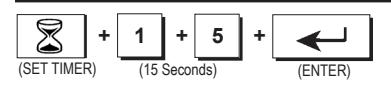
To set the latch timer, put the unit into the Program mode, (See Page 9). Press SET TIMER, then press the desired Latch Time (0 - 65,535 seconds), then press ENTER. A green light and beep means that the Latch Timer setting was changed. For example, to set the latch timer to 15 seconds, the following sequence would be used:
For longer latch times it may be easier to set the timer with hour: minute notation. Press SET TIMER; then press the number of hours (2 digits); then press the number of minutes; then press THRU; then ENTER. For example, to set the latch timer for 2 hours and 45 minutes the following sequence would be used:
(SET TIMER) (2 Hours, 45 Minutes) (THRU) (ENTER) + 0 + 2 + 4 + 5 + +
If you have set an extended latch time, but need to interrupt it, follow this procedure. Put the unit in Program Mode (see Page 9). Then press Set Timer then "1" then Enter. After the Program Mode expires, present a valid card to the reader. After one second the relay will return to its normal state. You will then have to reprogram the latch timer to the desired duration.
Set the Operating Mode:
The Radio Key® RKDT-SA-M/SA-S may be put into any of four operational modes. The Modes are as follows;
"1" - Active (Normal) -- LED is Off
"2" - Inactive (Locked) -- LED blinks Red
"3" - Door Unlocked -- LED blinks Green
"4" - Toggle Mode – LED is Off
In mode 1, a valid card or tag or closure of the remote open input will activate the relay for the time the latch timer is set.
Mode 2 deactivates the unit. No card or tag can activate the relay, but the remote open input will activate the relay.
In mode 3, the door is kept unlocked (the relay is kept latched).
In mode 4, when a valid card or tag is presented or the remote open input is activated, the relay changes its state from deactivated to activated or from activated to deactivated. The relay will stay in this state until another valid card or tag is presented or the remote input is activated and so forth.
To set the Operating Mode, put the unit into the Program mode, (See Page 9). Press MODE, then press either "1" , "2", "3", or "4". Press ENTER. The Access Control Unit will exit Programming
Mode and enter the selected Mode. For example, to set the unit to the inactive (locked) mode, the following sequence would be used:
(MODE) (Mode Number 2) (ENTER) + 2 +
To Exit Programming Mode Immediately:
Press MODE, then "1" (or 2, 3, or 4) and then press ENTER. This returns the unit to the selected mode immediately, bypassing the 15 second timeout.
(MODE) (Mode Number 1) (ENTER) + 1 +
Timed Antipassback
Timed antipassback is used to discourage card sharing. After one successful card use, the unit will treat that card as Void for a preset number of minutes. When timed antipassback is enabled, it will apply to all valid cards.
Enable Timed Antipassback
Place the unit in the Program Mode (see Page 9). Press SET TIMER, then press ADD, finally press ENTER.
(SET TIMER) (ENTER) (ADD) + +
Set Antipassback Timer
Place the unit in the Program Mode (see Page 9). Press SET TIMER then press THRU. Press the maximum number of minutes you want antipassback to apply (01 – 99). Press ENTER. (Antipassback can be set from one to ninety-nine minutes. Depending upon the clock cycle of the unit when a card is read, the actual antipassback time may be as little as one-half the time selected.) For example, to set the Antipassback Timer to 15 minutes, the following sequence would be used:
(SET TIMER) (THRU) (ENTER) + + 1 + 5 +
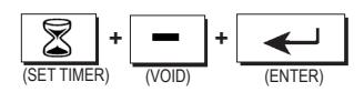
Disable Timed Antipassback.
Place the unit in the Program Mode (see Page 9). Press SET TIMER then VOID, finally press ENTER.
Configure the Relay
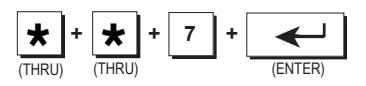
The relay is set at the factory to be normally open and to close upon presentation of a valid card or tag or upon activation of the remote open (Request to Exit) input. It may be changed to normally closed or to SecuRelay™ operation. A normally open relay is used for a "fail-secure" electric lock or door strike and to trigger a gate operator. A normally closed relay is used for "fail-safe" devices such as magnetic locks. The Secura Key SecuRelay™ (sold separately) is a remote intelligent relay used to prevent entry when the access control unit is physically attacked. (NOTE: When placed in the SecuRelay™ mode the "Remote Open" input is disabled.) To configure the relay, put the unit in the Program mode (See Page 9). Press THRU two times. Then press either the "6", "7" or "8". Press ENTER.
Selections are:
6. Normally Open (Factory default)
7. Normally Closed 8. SecuRelay™ Option.
For example, to configure the relay normally closed, the following sequence would be used:
Using the RKDT-SA-M/SA-S as a Wiegand Output Reader The RKDT-SA-M/SA-S can be connected to a multidoor access
control system (such as the Secura Key SK-ACP) using the Wiegand output. When any Radio Key® or HID® Proximity card or tag is presented to the unit, whether or not it has been programmed into the unit, the appropriate facility code and card ID and parity bits will be sent out via the white and green wires.
When outputting Wiegand formatted data from HID® cards, the bits are transmitted exactly as they are encoded on the card. The reader does not perform any internal processing, such as adding additional bits, calculating checksums, offsets, or decrypting any data.
Program the Input
The input is set at the factory as a Remote Open input. Connecting the brown and the black wire (usually with a push button switch) will activate the relay for as long as the switch is held, plus for the time set for the latch timer. This input may also be configured as an LED control. When configured as an LED control, grounding the brown wire will turn on the Red LED, grounding the orange wire will turn on the Green LED, grounding the yellow wire will turn on the beeper, and grounding the blue wire will turn on the Hold function.
To configure the input, put the unit into the Program mode, (See Page 9). Press THRU TWICE. Then press either the "1" or "2" button. Press ENTER. Selections are:
- "1" Remote Open (Factory default).
- "2" LED Control.
For example, to program the input for LED control, the following sequence would be used:
(THRU) (THRU) (Input No. 2) (ENTER) + + 2 +
BASIC OPERATION
To use the Radio Key® RKDT-SA-M/SA-S, simply hold your Radio Key® or HID® Card or tag near the Radio Key® RKDT-SA-M/SA-S Unit. The Radio Key® RKDT-SA-M/SA-S Unit generates an RF field, which causes the card or tag to transmit a unique ID Number back to the Unit.
If the card ID Number is stored in memory, the latch relay is activated, unlocking the controlled door or gate. A green light and a beep indicates that access is granted. If the card ID Number is not stored in memory, the door or gate remains locked and a red light and beep indicate that access is denied. Otherwise the LED is normally off.
Remote Open (Request to Exit) Input
When the Remote Open input is activated, the relay will activate. When the Remote Open input is deactivated, the relay will return to the inactive state after the latch timer times out. A green light and a beep indicates that access is granted.
NOTE: Remote Open Input is disabled when the unit is configured for use with SecuRelay™.
WARRANTY
"Secura Key products are warranted against defects in materials and assembly for life. In the event that any Secura Key manufactured product fails to perform as intended for any reason during the warranty period, Secura Key will replace the defective product with a new or refurbished product. Any reason includes vandalism, installation errors and "Acts of God" such as lightning, fire, flood, hurricane, etc. The warranty period begins on the date of shipment from our factory, or if sold through a Distributor, on the date of sale (original receipt or documentation is required). This warranty does not include your cost for taxes, duties, or installation expenses."
Warranty Limitations
"THE WARRANTY SET FORTH ABOVE IS EXCLUSIVE AND NO OTHER WARRANTY, WHETHER WRITTEN OR ORAL, IS EXPRESSED OR IMPLIED. SECURA KEY SPECIFICALLY DISCLAIMS ANY IMPLIED WARRANTIES OR MERCHANTABILITY AND FITNESS FOR A PARTICULAR PURPOSE. The remedies provided herein are the buyers' sole and exclusive remedies. In no event shall Secura Key be liable for damages in excess of the purchase price of the product, for direct, indirect, special, incidental or consequential damages (including loss of profits) arising out of the installation, use, or inability to use such product, or loss resulting from the operation or performance of any third party product or any systems in which a Secura Key product is incorporated, whether based on contract, tort or any other legal theory." Contact Secura Key for Card/Tag and Export Warranty Policies.
| Radio Key® RKDT-SA-M/SA-S | Operating Guide |
|---|
SPECIFICATIONS
Models RKDT-SA-M RKDT-SA-S
Physical
Depth 0.9" (2.28 cm) 0.84" (2.13 cm) Width 1.74" (4.19 cm) 3.20" (8.12 cm) Height 4.38" (11.12 cm) 4.50 (11.43 cm) Weight 3.42 oz. (97.09 gm) 6.67 oz. (189.15 gm)
Material ABS Lexan® Color Black Black
Power Requirements 5-14 VDC, 150 mA Max.
Wiegand Output Any Wiegand Format up to 40 bits Maximum Distance: 500 Ft.- 5 or 6 conductor 20 gauge
shielded cable
Outputs
SPST Solid State Relay, 1A max. @60 VAC or DC. Normally open or normally closed (field programmable). May also be used with SecuRelayTM intelligent relay module (sold separately).
Inputs
Programmable as Remote Open (requires contact closure); Bicolor (Red) LED Control.
Environment
Ambient Temperature -40° to +70° C (-40° to +158° F) Humidity 0% to 95% (non-condensing)
Operational
Reading Distance
Molded Card: Up to 6" (15.24 cm)
Key tag & ISO Card: Up to 5" (12.70 cm)
User Capacity
65,000 Radio Key® key tags or cards (26 or 32 bit),
or 26-bit HID® passive cards or key tags
10 Facility Codes
Card/Key Tag Operation Passive Transmit Frequency 125 kHz Memory Non-Volatile
Latch Timer Programmable 0.25 sec. to 18 hours or Toggle Mode
Accessories
RK-HHP Hand-held Programmer
RK-PS 9VDC, 200 mA, plug-in Power Supply,
120 VAC Input. For Access Unit Only. SK-SR SecuRelayTM - Smart relay module, DPDT.
This product complies with UL 294 Standards, with Part 15, Class B FCC Rules and (European Standards).
Secura Key 26
FCC ID: NNHDTR1 INSTRUCTION TO THE USER
"This device complies with Part 15 of the FCC rules. Operation is subject to the following two conditions: (1) this device may not cause harmful interference, and (2) this device must accept any interference received, including interference that may cause undesired operation."
This equipment has been certified to comply with the limits for a class B computing device, pursuant to FCC Rules. In order to maintain compliance with FCC regulations, shielded cables must be used with this equipment. Operation with non-approved equipment or unshielded cables is likely to result in interference to radio and TV reception. The user is cautioned that changes and modifications made to the equipment without the approval of the manufacturer could void the user's authority to operate this equipment.
Radio Key® RKDT-SA-M and RKDT-SA-S
Operating Guide
Revision A
20301 Nordhoff Street • Chatsworth, CA 91311
Phone: 818-882-0020 • Fax: 818-882-7052
TOLL FREE: 800-891-0020
mail@securakey.com • securakey.com