Securakey RKAR Auxiliary Reader Operating & Installation Guide
Open the original PDF document
View PDFRKAR Auxiliary Reader
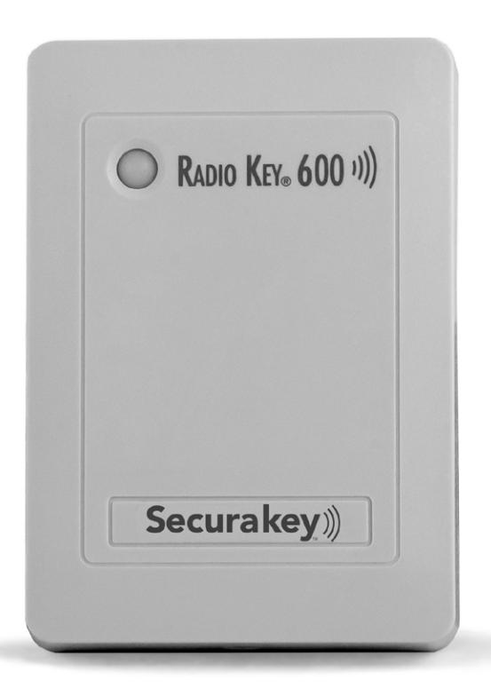
Installation & Operating Guide
RKAR AUXILIARY READER OPERATING & INSTALLATION GUIDE
INTRODUCTION
The RKAR Auxiliary Reader is an optional reader designed for use with the Radio Key® 600 single door proximity access control unit. The RKAR is recommended for extreme weather or higher security applications. It contains a bi-color LED indicator and a beeper. The reader is fully potted and sealed. A gasket is provided for exterior installation.
Parts Supplied: Auxiliary Reader
Gasket
Mounting Plate
2, 6-32 x 1/2" mounting screws
1, 4-40 x 5/16" Phillips housing screw
1, 4-40 x 5/16" Hex Socket, security housing screw
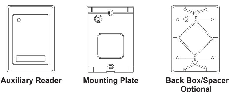
Figure 1 - RKAR Components
Installation Hints
The RKAR Auxiliary Reader consists of three parts: a mounting plate, a housing and an optional spacer (Figure 1).
When mounting the reader on metal, install the optional Back Box /Spacer RK600-BB (Figure 3) between the mounting plate and the mounting surface to minimize the loss of reading distance caused by the metal.
When mounting the RK600 Unit and Auxiliary Reader on opposite sides of a wall, offset the units by about 6" for the best reading distance.
If the Auxiliary Reader must be concealed, the RK-GM Glass Mount Kit can be used to permanently adhere the unit to the back of a glass window. Instructions are included with the kit.
Installation Procedure
-
1. Orient the mounting plate with the threaded insert at the bottom; attach it to a single-gang electrical box with two 6-32 x 1/2" screws (supplied); or attach directly to the wall surface, using anchor screws or toggle bolts (Figure 2).
- a. If using the optional spacer, insert spacer alignment pins into corresponding holes on the back of the mounting plate, then install both parts so that the spacer is closest to the wall or mounting surface (Figure 3).
- b. For exterior applications, install the thick gasket between the wall or mounting surface and the back of the mounting plate.
- c. If using the spacer with gaskets, install the thick gasket between the spacer and the mounting surface, install the mounting plate and spacer using the two 6-32 x 1-1/2" screws (supplied with the spacer), then place the thin gasket around the mounting plate (Figure 4).
-
2. Insert the cable end through the access hole in the mounting plate. Splice in additional wire, if necessary (Figure 5).
- a. Connect Plug P2 at the end of the Auxiliary Reader cable to Socket J2 at the RK600 Unit, grounding the shield at the RK600 Unit end only.
- b. Connect Plug P1 to Socket J1 on the RK600 Unit circuit board.
-
3. Attach the housing to the mounting plate:
- a. Hold the bottom end of the housing away from the mounting plate.
- b. Insert the two tabs (inside top of housing) into the two slots at the top of the mounting plate.
- c. Swing the bottom of the housing toward the mounting plate.
- d. Secure by installing the 4-40 x 5/16" Phillips screw (supplied) into the hole at the bottom. The 4-40 x 5/16" Hex Socket tamper-proof screw (supplied) can be substituted for additional security. The optional security tool (ST-2) is required in order to use the tamper-proof screw.
- 4. Apply power. The LED will flash once and the beeper will sound. Refer to the Radio Key® 600 Operating and Installation Manual for programming and operating instructions.
Do not locate the RK600 or RKAR with 2 feet of a PC monitor or CPU enclosure, or any other source of EMI (electro-magnetic interference) such as radio transmitters, elevators, large electric motors or fluorescent ballasts.
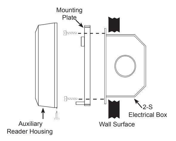
Figure 2 - Basic Installation
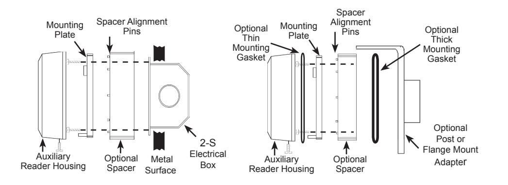
Figure 3 - Wall Mounting on Metal Surface with Optional Spacer
Figure 4 - Post/Flange Mounting
Extending the Auxiliary Reader Cable
A short cable assembly extends from the back of the Auxiliary Reader. This cable may be extended up to 30 feet . If the cable must be extended, for the best performance, use TWO SEPARATE CABLES: one unshielded, non-twisted, two-conductor wire to the antenna coil, Pins 1 & 2, plus a SEPARATE 4-conductor shielded cable to the LED and Beeper, Pins 3 - 6, (Figure 5). These cables can be run in the same conduit. Connect the cable shield from the LED/Beeper cable to the black wire (GND) on P1 at the RK600.
WARNING
Use of any Auxiliary Reader cable which combines all conductors inside one shield and/or uses twisted pair for the antenna lines will result in severely reduced reading distance. Failure to properly ground the cable shield for the LED/Beeper lines will also result in severely reduced reading distance. Route cable at least 2 feet away from any source of EMI (electromagnetic interference).
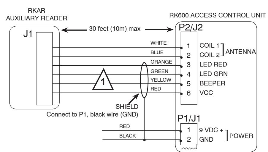

Use shielded cable for J2, pins 3 - 6, and unshielded, non-twisted separate cable for pins 1 & 2 (such as "zip cord", lamp cord or speaker wire).
Figure 5 - RKAR Wiring
Note: When power is applied to the RK600, the unit is calibrated for the current antenna configuration. Always connect the Auxiliary Reader first, before applying power to the RK600.
Surface-Mounted Wiring
For installations where it is necessary to run cable along the wall surface (such as in a wall-mounted modular raceway) small break-away knockouts are provided on the bottom of the RK600 and Auxiliary Reader housings, as well as on the Spacer. Remove the knockouts with small pliers, and butt the raceway up against the opening in the housing to conceal the cable.
WARRANTY (U.S. and Canadian)
"Secura Key products are warranted against defects in materials and workmanship for LIFE. Secura Key will replace any Secura Key manufactured product, except cards or tags, returned to us freight prepaid within the warranty period. This warranty does not include freight, taxes, duties, or installation expenses. THE WARRANTY SET FORTH ABOVE IS EXCLUSIVE AND NO OTHER WARRANTY, WHETHER WRITTEN OR ORAL, IS EXPRESSED OR IMPLIED. SECURA KEY SPECIFICALLY DISCLAIMS ANY IMPLIED WARRANTIES OR MERCHANTABILITY AND FITNESS FOR A PARTICULAR PURPOSE. The remedies provided herein are the buyers' sole and exclusive remedies. In no event shall Secura Key be liable for direct, indirect, special, incidental or consequential damages (including loss of profits), whether based on contract, tort or any other legal theory." Contact Secura Key for Export Warranty Policy.
European Community Approvals:
This is a peripheral unit to the RK600/Rk600e/RK600T access control units. Please see manuals for the RK600/RK600e for "User Information", or visit our website, www.securakey.com.


20301 Nordhoff Street • Chatsworth, CA 91311 818-882-0020 • Fax: 818-882-7052 TOLL FREE: (800) 891-0020
E-mail: mail@securakev.com • Web site: www.securakev.com
3320880 7032
RKAR Installation & Operating Guide
20301 Nordhoff Street • Chatsworth, CA 91311
Phone: 818-882-0020 • Fax: 818-882-7052
TOLL FREE: 800-891-0020
mail@securakey.com • securakey.com