Schlage D Series Knob Service Manual 106722
Open the original PDF document
View PDF


This manual contains a complete listing of parts and assemblies of "D" series locks manufactured by Schlage Lock Company, beginning in 1940. These locks are identified with the symbol MD40 stamped on the lock housing. Exploded views of each lock function are provided with an accompanying dot chart to identify parts for replacement purposes.
In addition, this manual provides lock trim ordering procedures, cylinders, latches and strikes, and all auxiliary components of "D" series MD40 locks. Orders for finished components should always show the finish designation. Orders for all Schlage products must be placed through a registered Schlage dealer or representative.
Schlage "D" series lock parts are manufactured to extremely close tolerances and are interchangeable between functions using the same parts. Conversion of functions is accomplished by identifying the parts necessary for substitution and following the assembly procedures as illustrated on the lock drawings.
For items not listed in this technical manual, contact the Schlage General Offices for availability or allowable substitutions.
The Schlage Lock Company reserves the right to make changes in designs and specifications or to make additions or improvements on its products previously manufactured. The Schlage Lock Company is not responsible for any modification, addition, or alteration to our products by others.
Index
| Function Assemblies | Description | Page |
|---|---|---|
| Passage latch | ||
| Exit lock | ||
| D12DEL - Discontinued | Electrically locked | |
| D12DEU - Discontinued | Electrically unlocked | 4 |
| D25D | Exit lock | 5 |
| Patio lock | ||
| D40S | Bath/Bedroom privacy | 7 |
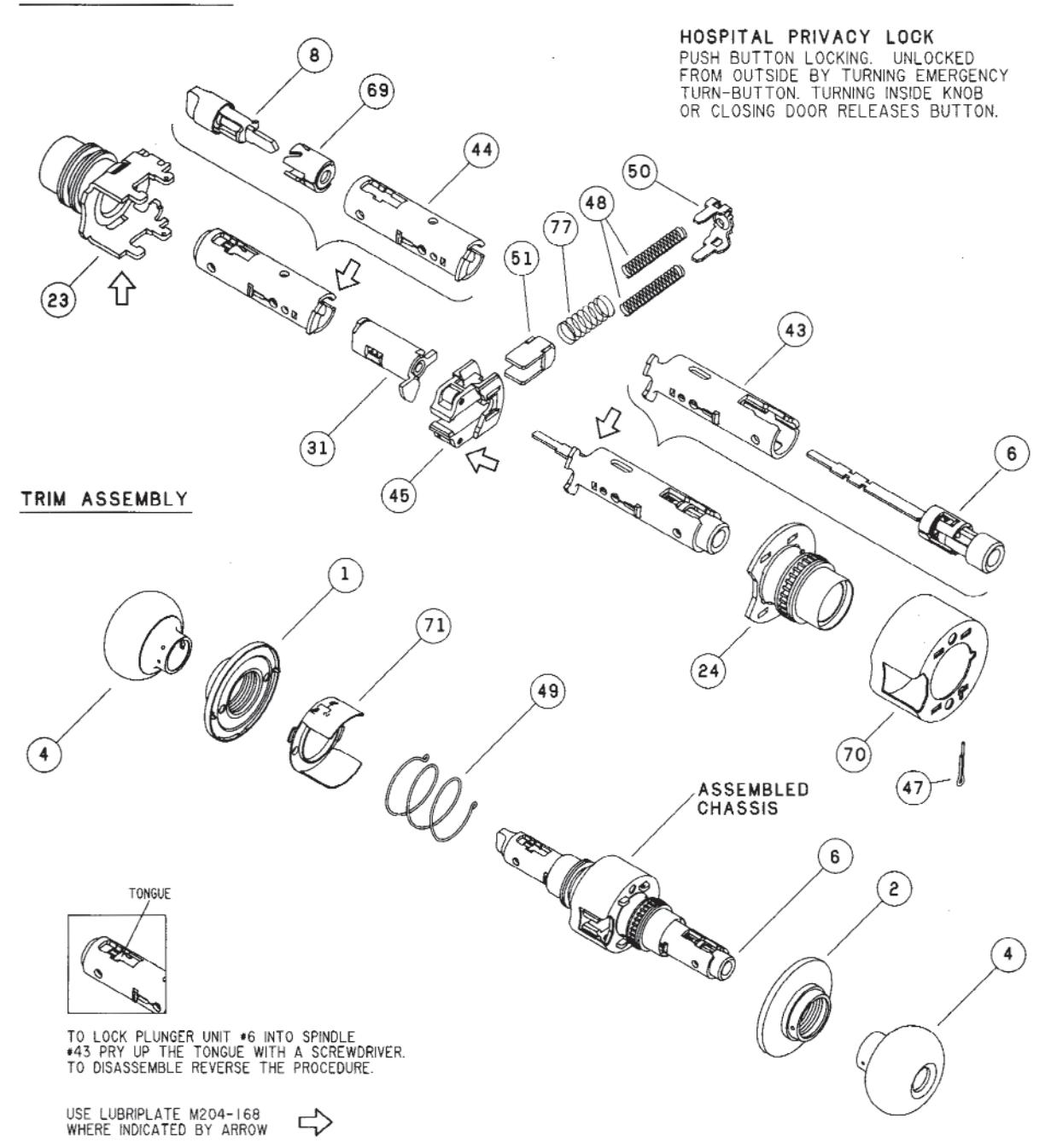
| D44S | Hospital privacy lock | 8 |
| Entrance lock | ||
| D55PD - Discontinued | Service station lock | 10 |
| D60PD | Vestibule lock | 11 |
| D66PD | Store lock | 12 |
| D70PD | Classroom lock | 13 |
| D72PD | Communicating lock | 14 |
| Corridor lock | ||
| D76PD | Classroom hold-back lock | 16 |
| D80PD | Storeroom lock | 17 |
| Electrically locked | ||
| D80PDEU | Electrically unlocked | 19 |
| D82PD | Institution lock | 20 |
| D85PD | Hotel/Motel lock | 21 |
| Dummy trim | ||
| Parts index | Dot charts | 23-25 |
| Replacement parts | 26 | |
| Cylinder units & parts | 27 | |
| Latches & strikes | 28 | |
| Electrified locks | 29 | |
| Interchangeable core | 30-31 | |
| Designs | 32 | |
| ning | ||
| or reinforcements | ||
| Installation instructions | 35-37 | |
| Keys, key array chart, key gauge, | cylinder loading tool | 38 |

D12D - DISCONTINUED
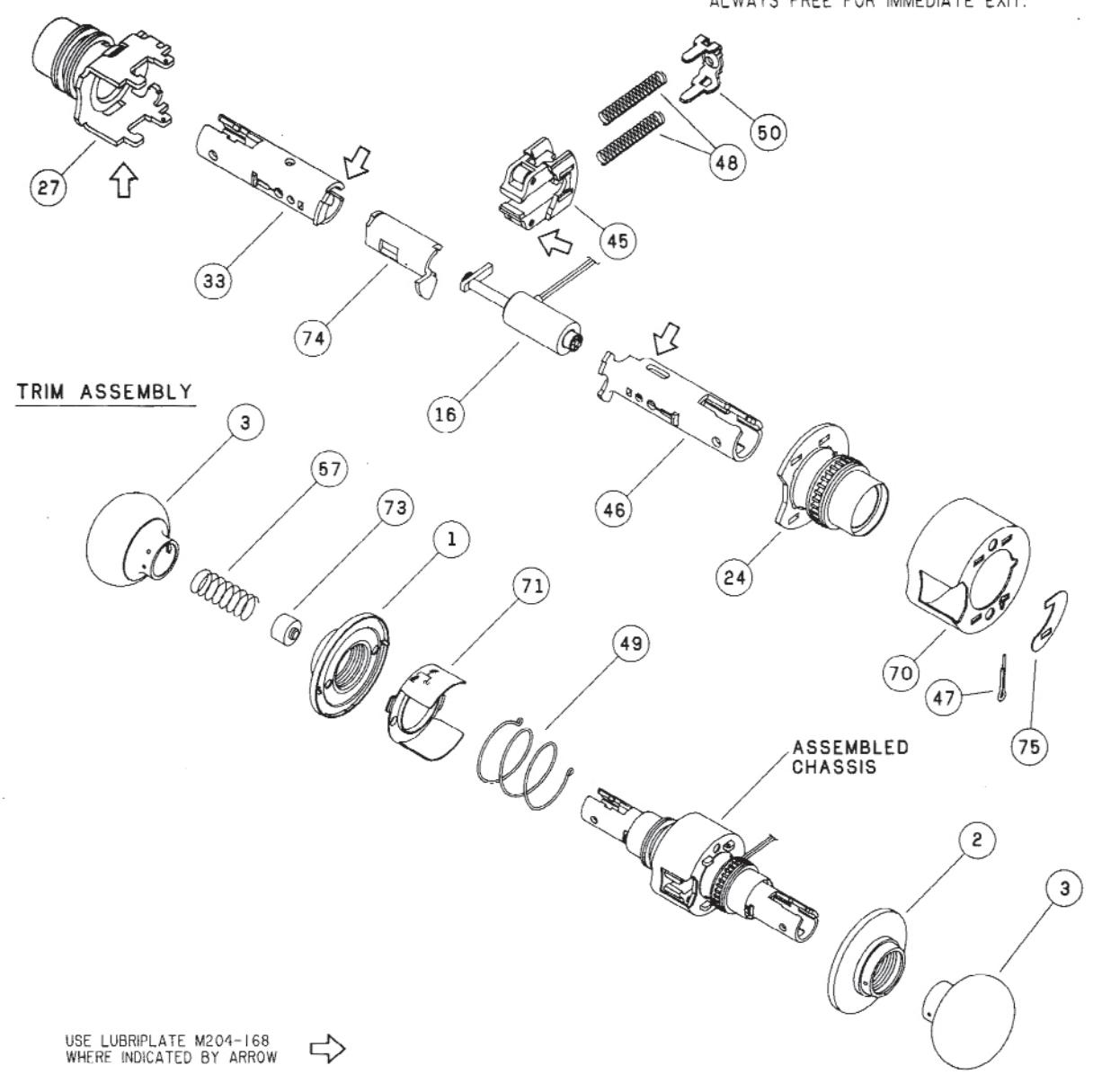
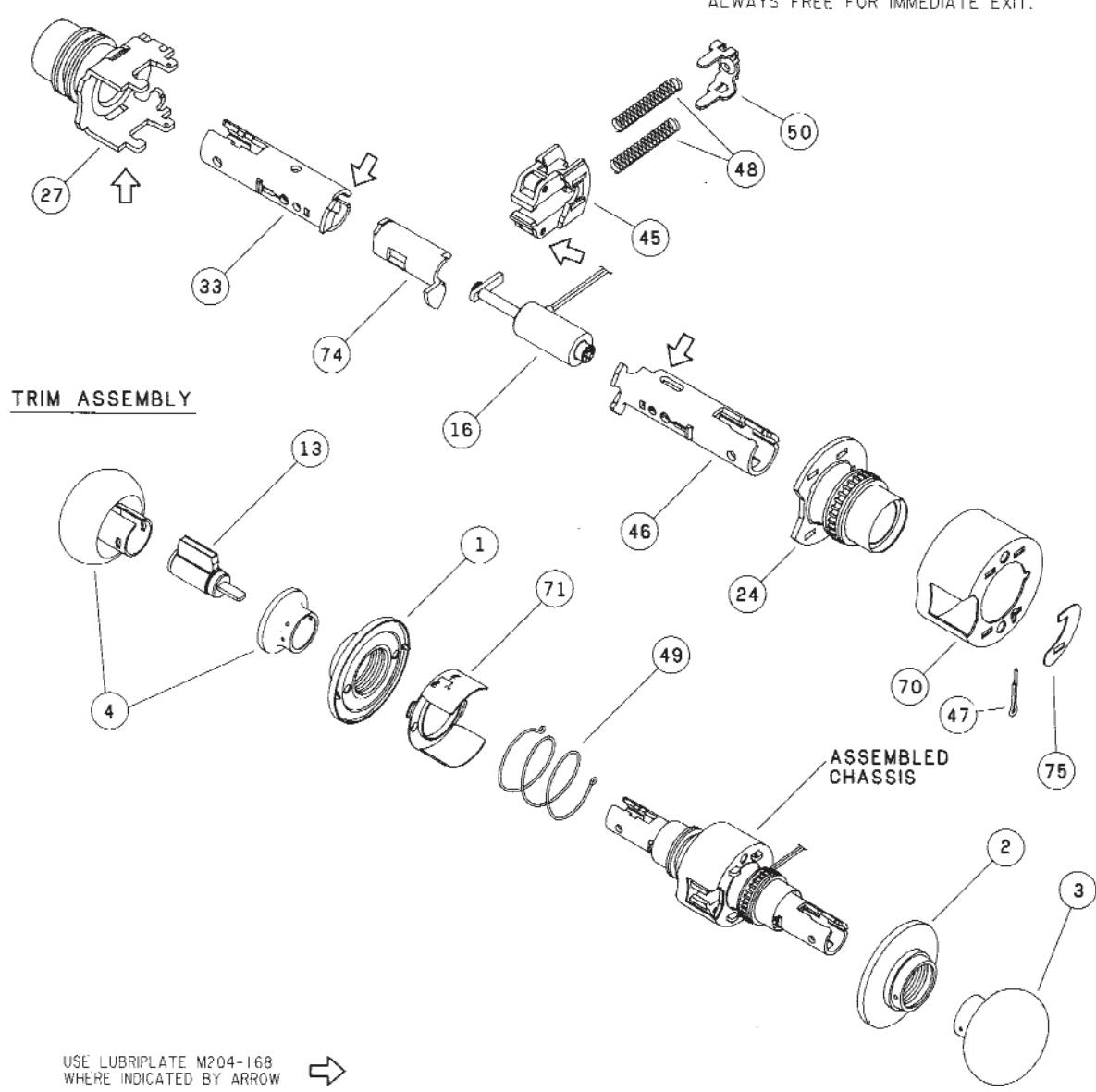
CHASSIS ASSEMBLY EXIT LOCK UNLOCKED BY KNOB INSIDE ONLY. OUTSIDE KNOB ALWAYS FIXED. (50) (45) (43) TRIM ASSEMBLY (24) (73) (70) ania) (71) Ô (49) (a)ASSEMBLED CHASSIS 3) USE LUBRIPLATE M204-168 WHERE INDICATED BY ARROW
D12DEL - DISCONTINUED
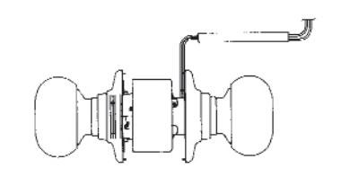
CHASSIS ASSEMBLY
ELECTRICALLY LOCKED AUXILIARY LATCH DEADLOCKS LATCHBOLT WHEN DOOR IS CLOSED. OUTSIDE KNOB CONTINUOUSLY LOCKED ELECTRICALLY UNTIL UNI OCKED BY SWITCH OR POWER FAILURE. INSIDE KNOB ALWAYS FREE FOR IMMEDIATE EXIT.

D12DEU - DISCONTINUED
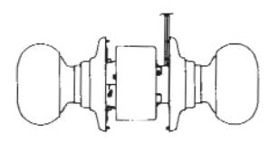
CHASSIS ASSEMBLY
ELECTRICALLY UNLOCKED AUXILIARY LATCH DEADLOCKS LATCHBOLT WHEN DOOR IS CLOSED. OUTSIDE KNOB CONTINUOUSLY LOCKED UNTIL UNLOCKED BY ELECTRIC CURRENT. INSIDE KNOB ALWAYS FREE FOR IMMEDIATE EXIT.
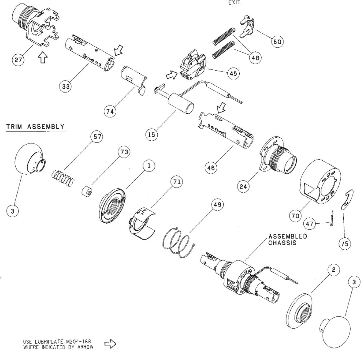
D25D
CHASSIS ASSEMBLY
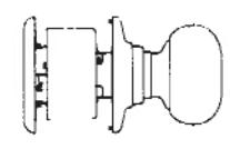
EXIT LOCK BLANK PLATE OUTSIDE. INSIDE KNOB ALWAYS UNLOCKED.

USE LUBRIPLATE M204-168 WHERE INDICATED BY ARROW

D30D
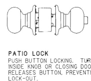
CHASSIS ASSEMBLY
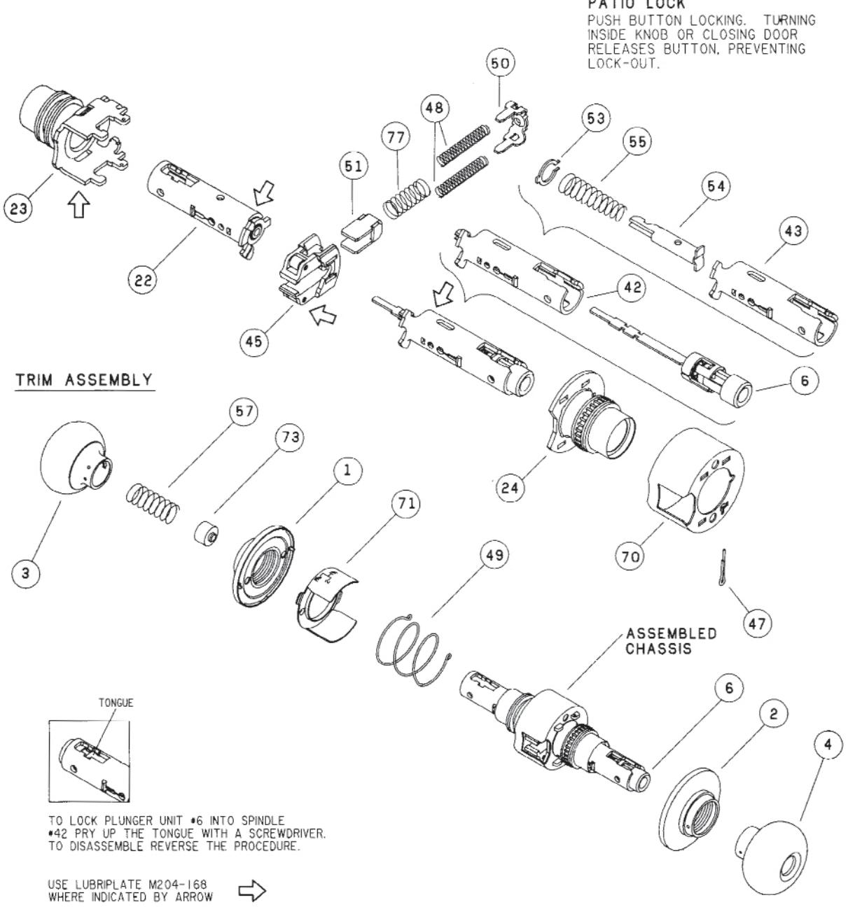

D40S
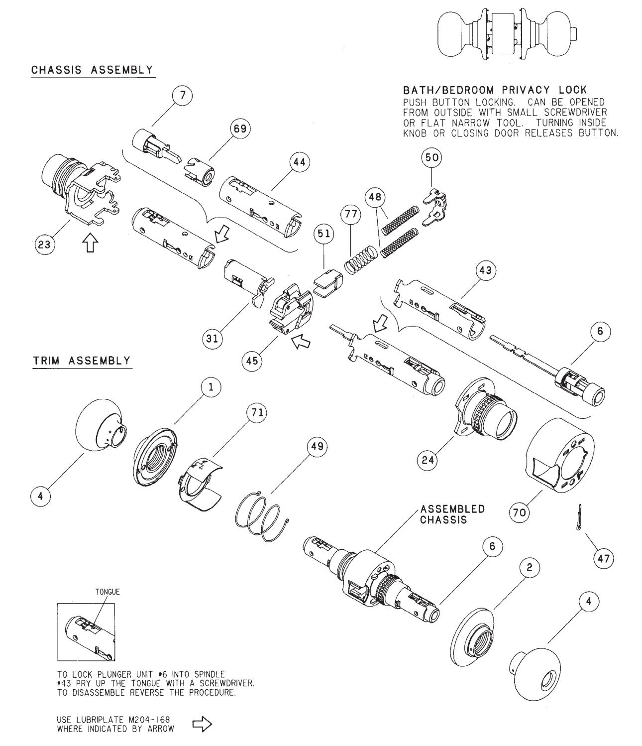

D44S
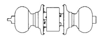
CHASSIS ASSEMBLY
D53PD
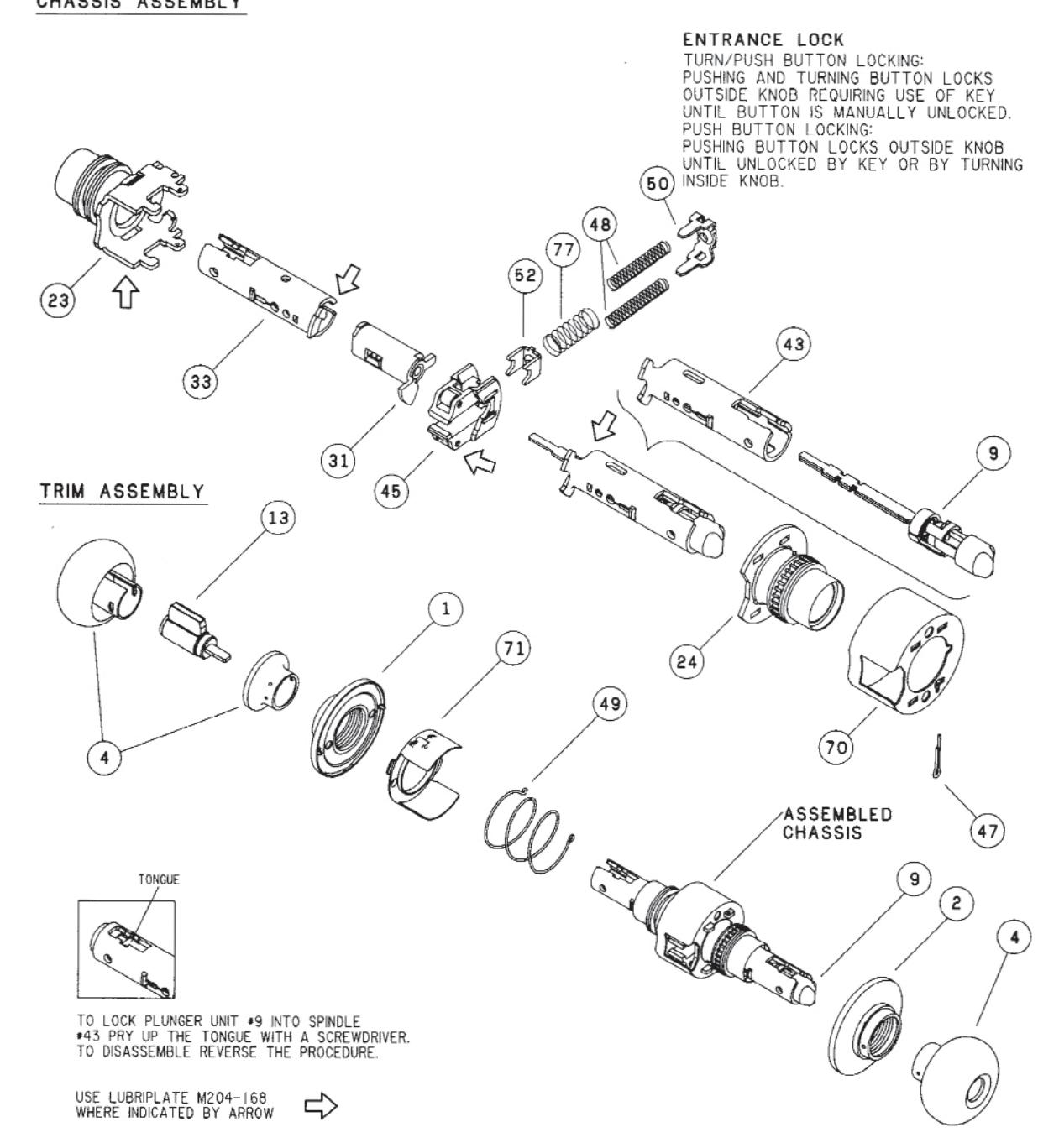
CHASSIS ASSEMBLY

D55PD - DISCONTINUED
CHASSIS ASSEMBLY
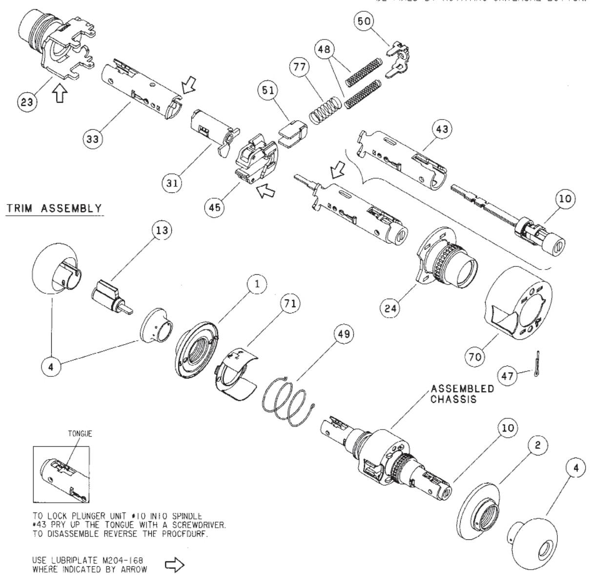
SERVICE STATION LOCK
UNLOCKED BY KEY FROM OUTSIDE WHEN OUTER KNOB IS LOCKED BY UNIVERSAL BUTTON IN INSIDE KNOB. CLOSING DOOR RELEASES BUTTON. OUTSIDE KNOB MAY BE FIXED BY ROTATING UNIVERSAL BUTTON.

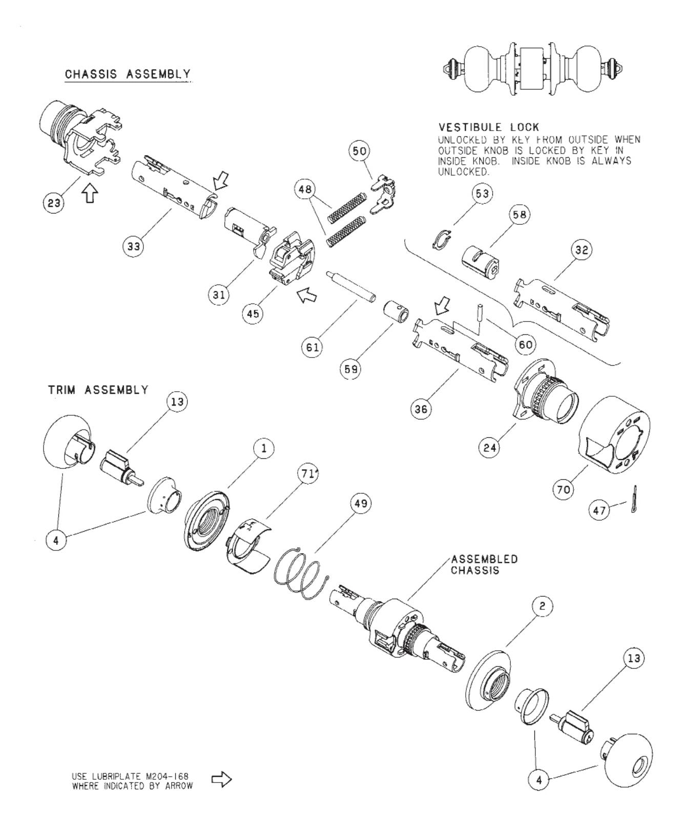
D60PD
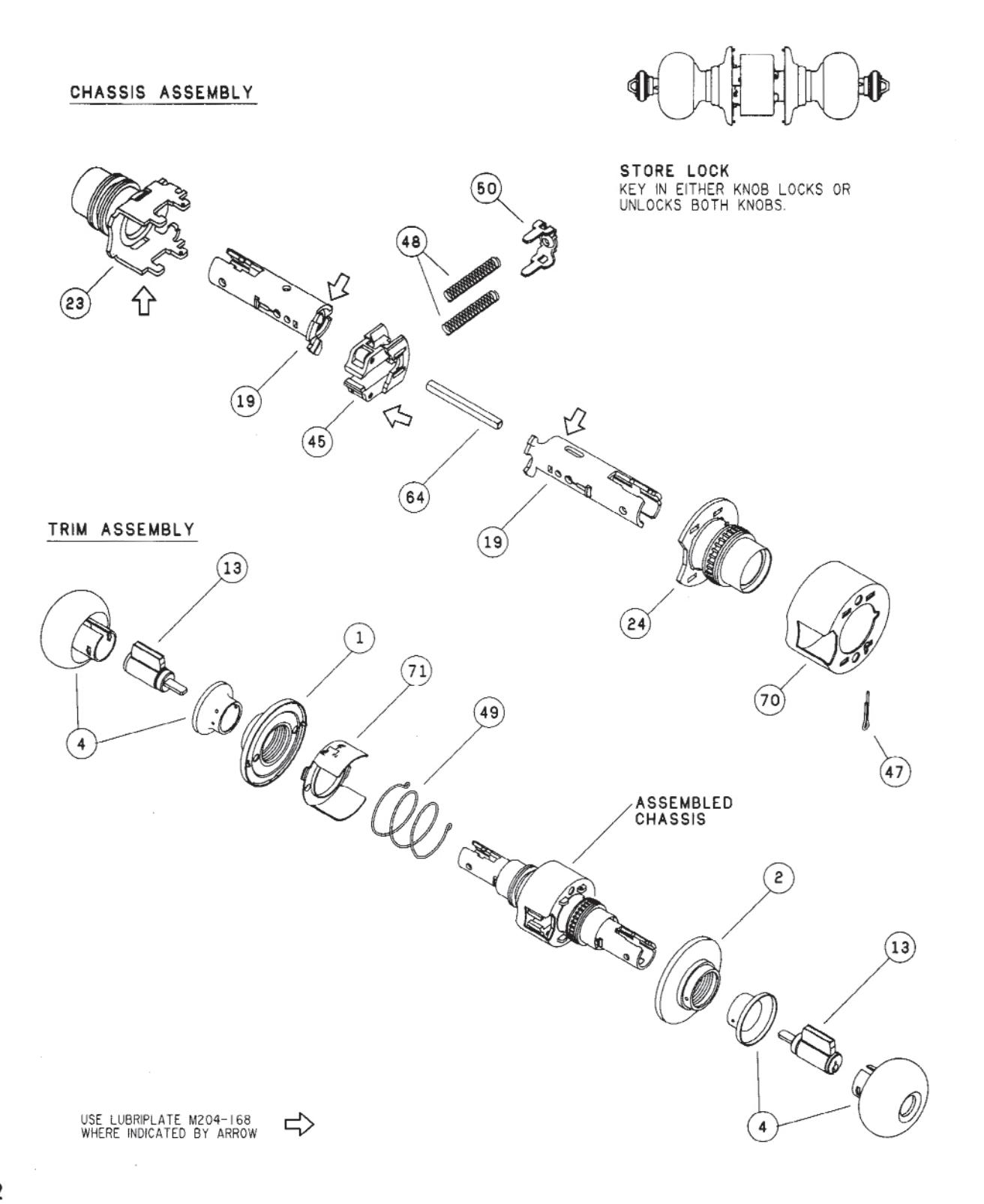
D66PD
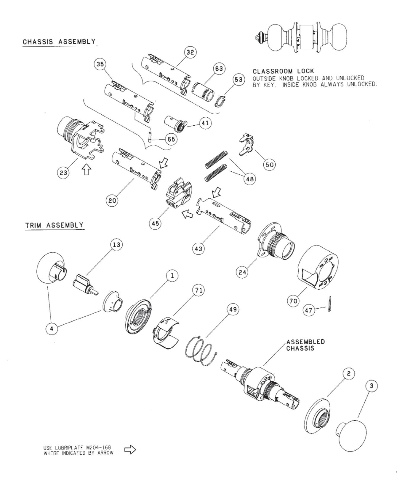
D70PD
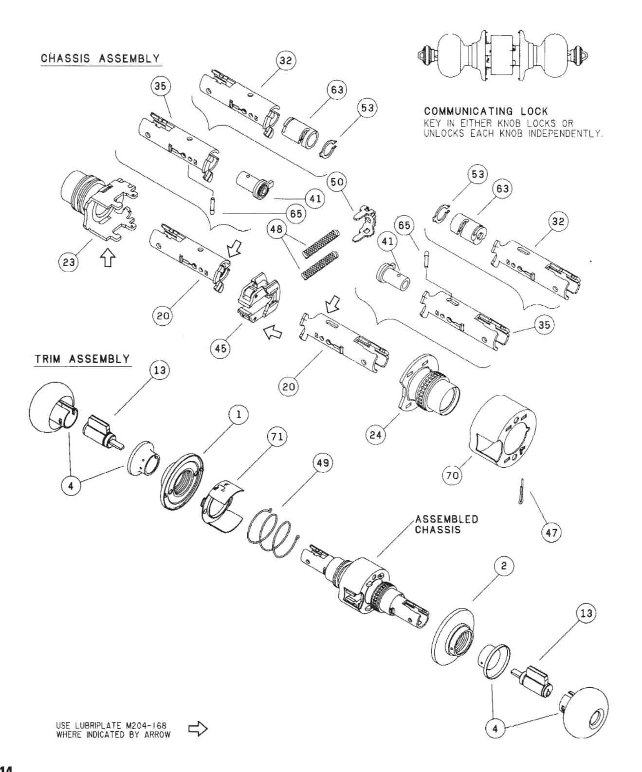
D72PD

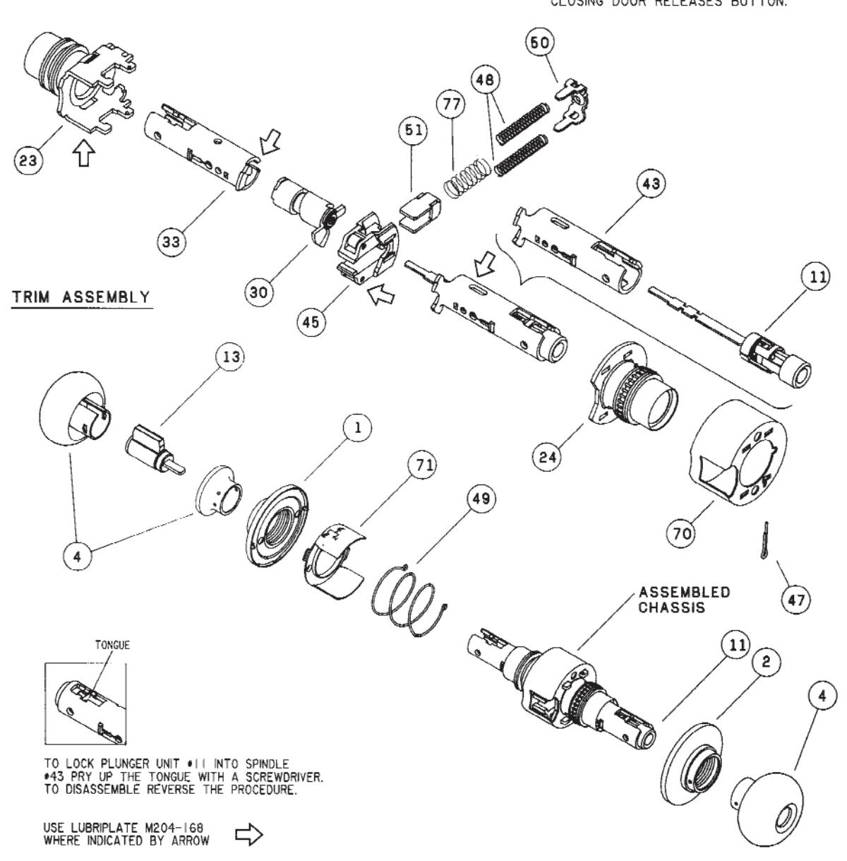
D73PD
CHASSIS ASSEMBLY
CORRIDOR LOCK LOCKED OR UNLOCKED BY KEY FROM OUTSIDE. PUSH BUTTON LOCKING FROM INSIDE. TURNING INSIDE KNOB OR CLOSING DOOR RELEASES BUTTON.
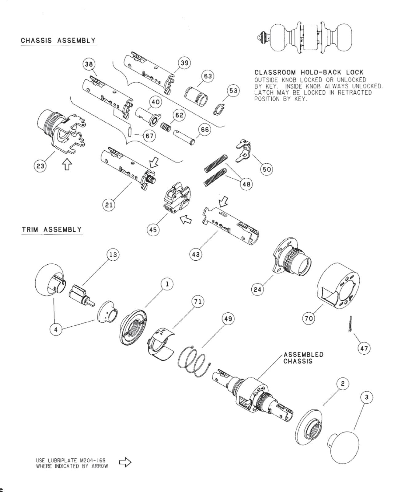
D76PD

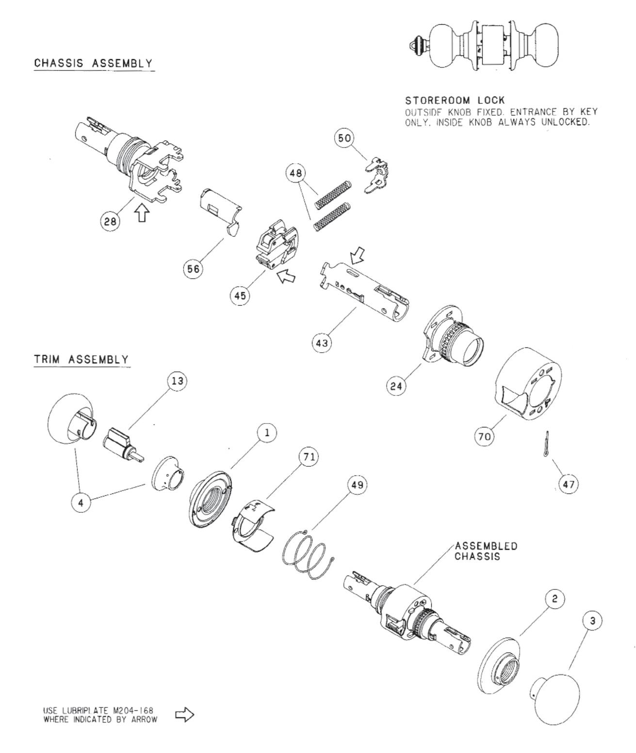
D80PD

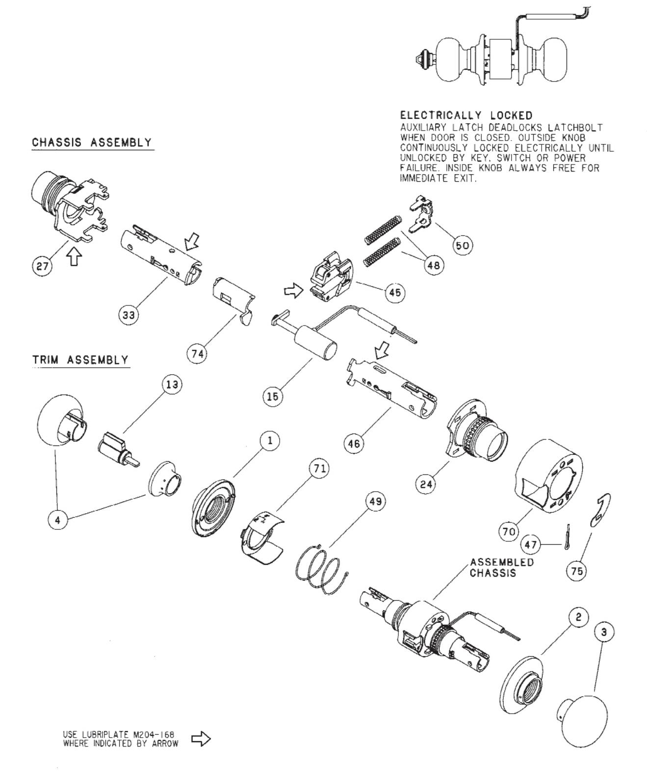
D80PDEL
D80PDEU
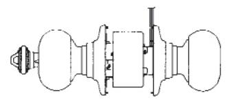
CHASSIS ASSEMBLY
ELECTRICALLY UNLOCKED
WHEN DOOR IS CLOSED, OUTSIDE KNOB CONTINUOUSLY LOCKED UNTIL UNLOCKED BY KEY OR ELECTRIC CURRENT, INSIDE KNOB ALWAYS FREE FOR IMMEDIATE EXIT.
D82PD
CHASSIS ASSEMBLY
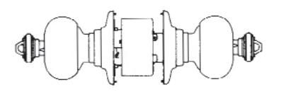
INSTITUTION LOCK BOTH KNOBS FIXED. ENTRANCE BY KEY IN EITHER KNOB.
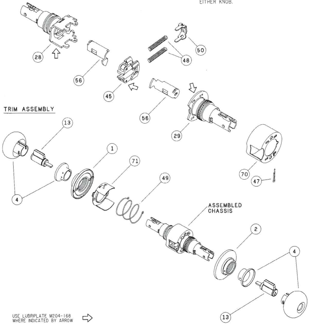
D85PD
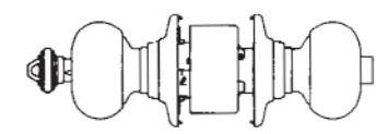
(77)
(51)
1
(71)
(49)
CHASSIS ASSEMBLY
(37)
(34)
(14)
(45)
(28)
TRIM ASSEMBLY
TONGUE
USE LUBRIPLATE M204-168 WHERE INDICATED BY ARROW
TO LOCK PLUNGER UNIT •12 INTO SPINDLE •42 PRY UP THE TONGUE WITH A SCREWDRIVER. TO DISASSEMBLE REVERSE THE PROCEDURE.
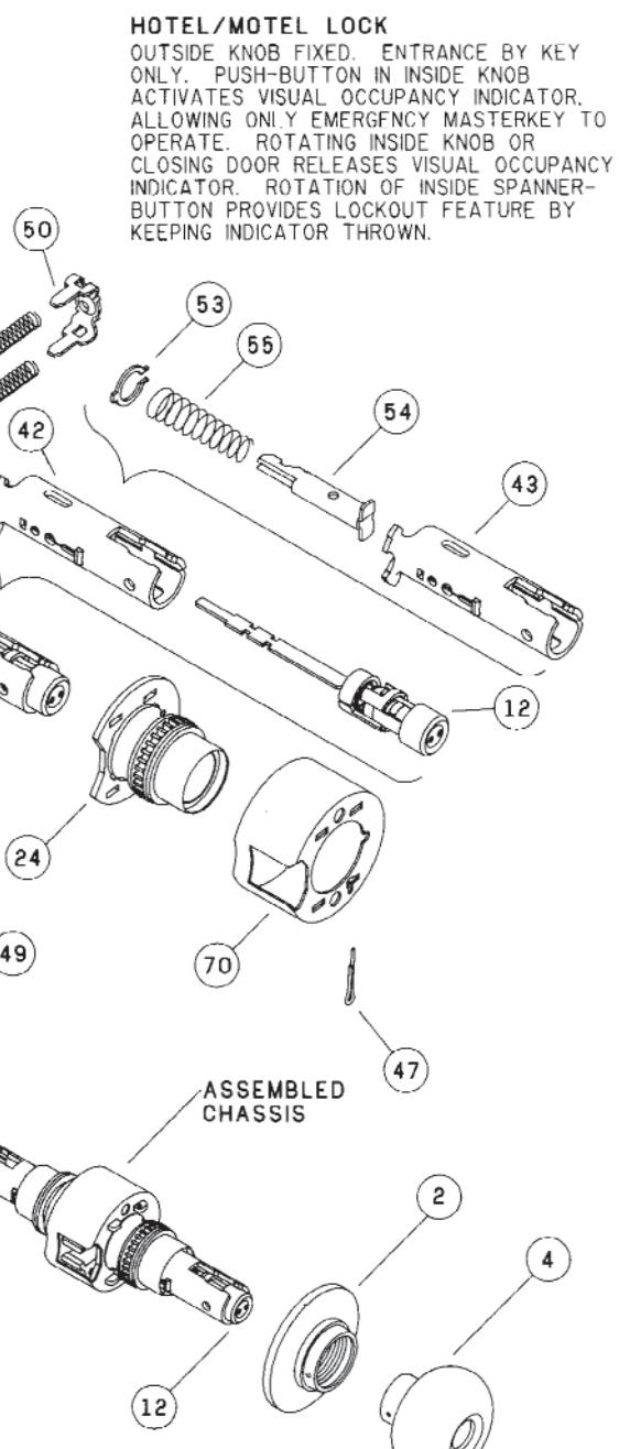
D170
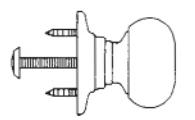
SINGLE DUMMY TRIM DUMMY TRIM FOR ONE SIDE OF DOOR. USED FOR DOOR PULL OR AS MATCHING INACTIVE TRIM.
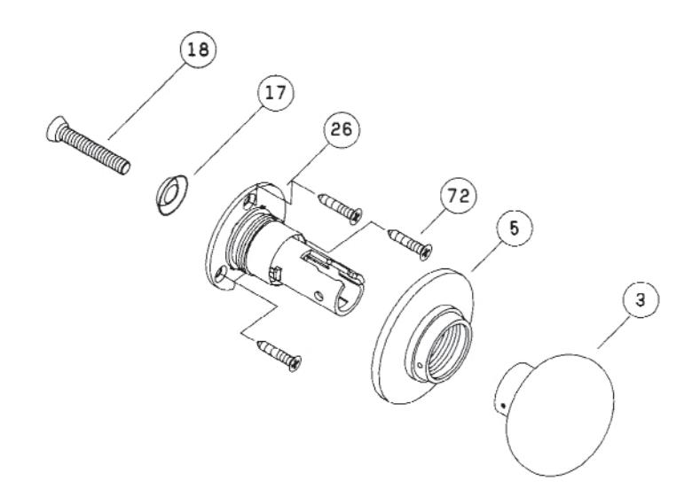
TRIM ASSEMBLY
| STANDA | RD D-LOCKS | Ä | ME | NACE OF THE | MED | WSCOWN. | MED | ||||||||||||||||
|---|---|---|---|---|---|---|---|---|---|---|---|---|---|---|---|---|---|---|---|---|---|---|---|
| SYM. NO. | DESCRIPTION | / |
/
&/ |
\\\\\\\\\\\\\\\\\\\\\\\\\\\\\\\\\\\\\\ | 105/0 /30/0 | DEL MSCONTINUED | CSO VISCONIANE |
|
|2| |
\s\
\s\ |
\&/ | 0350 | 1005/ Odos/ | 000 | ( de ) | 000 | /3000 V | 13000 | 0000 | |||||
| DESCRIP HON | $\\\ \c | t | 1 |
|
- | - | Ĺ | ||||||||||||||||
| 1 04-001 | OUTSIDE ROSE | Ø | (2) | (2) | Ø | _ | 0 | 0 | 0 | 0 | (2) | (2) | 0 | 0 | (2) | _ | |||||||
| 2 04-002 | INSIDE ROSE | 0 | 0 | Ø | 0 | 0 | 0 | (2) | 0 | 0 | 0 | 0 | 0 | @ | 0 | 0 | 0 | ||||||
| 3 04-006 | CLOSED KNOB | 2 | 2 | 2 | 2 | _ | Ø | 0 | 0 | 0 | Ø | ||||||||||||
| 4 04-007 | OPEN KNOB | _ | 0 | 2 | 2 | 2 | 2 | 2 | 2 | 0 | 2 | 2 | 0 | 0 | 2 | 2 | _ | ||||||
| 5 04-017 | ROSE | ||||||||||||||||||||||
| 6 04-020 | O/S PLUNGER UNIT | 0 | (2) | Ø | |||||||||||||||||||
| 7 04-021 | O/S PLUNGER UNIT | (2) | |||||||||||||||||||||
| 8 04-022 | PLUNGER, OUT | Ø | |||||||||||||||||||||
| 9 04-023 | I/S PLUNGER UNIT | 0 | |||||||||||||||||||||
| 10 04-024 | I/S PLUNGER UNIT | 0 | |||||||||||||||||||||
| 11 04-025 | I/S PLUNGER UNIT | 0 | |||||||||||||||||||||
| 12 04-026 | I/S PLUNGER UNIT | ||||||||||||||||||||||
| 13 23-001 | CYLINDER | 2 | 2 | 0 | 2 | (2) | 2 | ||||||||||||||||
| 14) 23-003 | CYLINDER | 0 | |||||||||||||||||||||
| 15) 38-072 | SOLENOID & DIODE | 0 | |||||||||||||||||||||
| 16 38-073 | SOLENOID & DIODE | 0 | 0 | ||||||||||||||||||||
| 17 A501-171 | WASHER | (2) | |||||||||||||||||||||
| 18 A501-746 | SCREW | 0 | |||||||||||||||||||||
| 19 C100-059 | SPINDLE & PLUG | 2 | |||||||||||||||||||||
| 20 C100-062 | SPINDLE & PLUG | 0 | 2 | ||||||||||||||||||||
| ②1) C100-255 | SPINDLE & PLUG | 0 | |||||||||||||||||||||
| SPINDLE & PLUG | 0 | ||||||||||||||||||||||
| 23 C102-522 | HUB & CAP OUT | 0 | 0 | 0 | 0 | 0 | 0 | 0 | 0 | 0 | |||||||||||||
| HUB & CAP INS | 0 | 0 | 0 | 0 | 0 | 0 | 0 | 0 | 0 | 0 | 0 | 0 | 0 | 0 | 0 | 0 | 0 | ||||||
| (25) C102-540 | HUB & FRAME | 0 | |||||||||||||||||||||
| HUB & CAP INS | |||||||||||||||||||||||
| HUB & CAP OUT | 0 | ( | - | 0 | |||||||||||||||||||
| _ | HUB & CAP OUT | - | _ | - | 0 | ||||||||||||||||||
| HUB & CAP INS | 0 | ||||||||||||||||||||||
| 0102 012 | HOD G ON HO | - ! | 40 |

| ST | ANDA | RD D-LOCKS | 4 | 3 | 3 | P. CE | MADOS | C. J. | ||||||||||||||||
|---|---|---|---|---|---|---|---|---|---|---|---|---|---|---|---|---|---|---|---|---|---|---|---|---|
| / | /2 | 000/ |
.
|
. / | / | / | / | /8 | 100s/ | / | / | / | / | / | / | / | /> | / | / . | |||||
| SYM. | NO. | DESCRIPTION |
/
$/5 |
0/5/5/00Mm |
!
!} !} |
2000 / 0000 | 5/0 |
/
5/3/0 |
0000 | 0/2/0 | 0000 | Odno O | Jano O | 3000 | ||||||||||
| 30 c | 102-837 | CAM & PLUG | 0 | |||||||||||||||||||||
| 31) c | 102-840 | CAM & PLUG | (2) | (2) | (2) | (2) | (2) | |||||||||||||||||
| 32 c | 203-367 | SPINDLE & CATCH | Ø | 2 | ||||||||||||||||||||
| 33 c | 203-374 | SPINDLE & CATCH | 0 | 0 | (2) | (2) | 0 | 0 | ||||||||||||||||
| 34) C | 203-376 | PLUG | 0 | |||||||||||||||||||||
| 35 C | 203-390 | SPINDLE & CAM | 0 | 2 | ||||||||||||||||||||
| 36 c | 203-391 | SPINDLE & CAM | (20) | |||||||||||||||||||||
| 37 c | 203-411 | SPINDLE & SPRING | (2) | |||||||||||||||||||||
| (38) C | 203-491 | SPINDLE & CAM | 0 | |||||||||||||||||||||
| 39 c | 203-492 | SPINDLE & CATCH | (2) | |||||||||||||||||||||
| 203-493 | PLUG | |||||||||||||||||||||||
| (41) c | 203-733 | PLUG | 2 | |||||||||||||||||||||
| 42 c | 203-858 | SPINDLE & HAMMER | 0 | |||||||||||||||||||||
| 43 c | 203-916 | SPINDLE & CATCH | 2 | (3) | 0 | 0 | 0 | (2) | 0 | 0 | 0 | (20) | 0 | |||||||||||
| (44) C | 203-917 | SPINDLE & CATCH | 0 | |||||||||||||||||||||
| 45 C | 303-006 | SLIDE & ROLLERS | 0 | 0 | 0 | (2) | 0 | 0 | (2) | (2) | 0 | 0 | 0 | 0 | 0 | 0 | (2) | |||||||
| (46) C | 303-400 | SPINDLE & CATCH | 0 | 0 | 0 | |||||||||||||||||||
| 47 0 | 503-008 | COTTER PIN | 0 | 0 | 0 | 0 | 0 | 0 | (2) | 0 | 0 | (3) | ② | 0 | 0 | 0 | 0 | 0 | 1 | |||||
| (48) C | 503-019 | SPRING, SLIDE | 2 | 2 | 2 | 2 | 2 | 2 | 2 | 2 | 2 | 2 | 2 | 2 | 2 | 2 | 2 | 2 | 2 | 2 | 2 | 2 | 2 | |
| (49) C | 503-308 | SPRING, ANCHOR | 0 | 0 | 0 | 0 | 0 | 0 | 0 | 0 | 0 | 0 | Ø | 0 | (2) | 0 | 0 | 0 | 0 | 0 | 0 | 0 | ||
| 60 0 | 2503-314 | SEAT, SLIDE SPRING | 0 | 0 | 0 | 0 | 0 | 0 | 0 | 0 | 0 | 0 | 0 | 0 | 0 | 0 | 0 | 0 | 0 | 0 | 0 | 0 | 0 | |
| (51) ( | 0604-187 | CATCH, SLIDE | 0 | 0 | (2) | 0 | 0 | Ø | ||||||||||||||||
| (52) C | 0604-188 | CATCH, SLIDE | 0 | |||||||||||||||||||||
| WASHER | 0 | 0 | 2 | 0 | 0 | |||||||||||||||||||
| HAMMER, PLUNGER | 0 | 0 | ||||||||||||||||||||||
| 0503-335 | SPRING, HAMMER | 0 | 0 | |||||||||||||||||||||
| 0503-339 | SPINDLE, KEY | - | 0 | 2 | ||||||||||||||||||||
| 2503-353 | SPRING, STOP | 0 | 0 | 0 | 0 | |||||||||||||||||||
| 2503-359 | CAM, KEY | 0 |
| STANDA | ARD D-LOCKS | Š | V. V. | OJAN.E. | MED | WSCOWN. | UMED | ||||||||||||||||
|---|---|---|---|---|---|---|---|---|---|---|---|---|---|---|---|---|---|---|---|---|---|---|---|
| SYM. NO. | DESCRIPTION | /5 |
/
3% |
| | 1505/08/SONY | 00/3/3/ | 05//05/ | OJON / OJO | 30% | 2/20 | 0000 | 005/1000/ | 000 | 0000 |
|3000 |
|3000 | 0 |
13000 | 07/0 | ||||||
| 69 C503-360 | RIDER, CAM | 0 | |||||||||||||||||||||
| 60 C503-361 | PIN, CAM | 0 | |||||||||||||||||||||
| 61 C503-362 | PLUNGER | 0 | |||||||||||||||||||||
| 62 C503-364 | SPRING | 0 | |||||||||||||||||||||
| 63 C503-368 | SPINDLE & CATCH | 2 | |||||||||||||||||||||
| 64 C503-371 | PLUNGER | 0 | |||||||||||||||||||||
| 65 C503-400 | PIN | 0 | 2 | ||||||||||||||||||||
| 66 C503-508 | RIDER | 0 | |||||||||||||||||||||
| 67 C503-509 | PIN | 0 | |||||||||||||||||||||
| 68 C503-775 | ROSE OUTSIDE | 0 | |||||||||||||||||||||
| 69 C503-965 | SLEEVE , PLUNGER | 0 | 0 | - | |||||||||||||||||||
| 70 C603-500 | HOUSING, SLIDE | (3) | 0 | 0 | 0 | 0 | 0 | 0 | 0 | 0 | 0 | 0 | 0 | 0 | 0 | 0 | 0 | 0 | 0 | 0 | |||
| 71) C603-501 | ANCHOR | 0 | 0 | 0 | 0 | 0 | 0 | 0 | 0 | 0 | 0 | 0 | 0 | 0 | 0 | 0 | 0 | 0 | 0 | 0 | |||
| 72 C603-897 | SCREWS | 3 | |||||||||||||||||||||
| 73 0604-203 | STOP | 0 | 0 | 0 | 0 | ||||||||||||||||||
| 74 C604-204 | SPINDLE, KEY | 0 | 0 | 0 | 0 | ||||||||||||||||||
| 75 C604-205 | CLIP, RETAINING, SOL. | 0 | 0 | 0 | 0 | ||||||||||||||||||
| 76 C604-237 | PIN | 0 | |||||||||||||||||||||
| 77 C604-191 | SPRING, CATCH, SLIDE | 0 | 0 | 0 | 0 | 0 | 0 | 0 | |||||||||||||||
| 7 | |||||||||||||||||||||||
| | | |||||||||||||||||||||||
| - | _ | - | - | 1 | _ | _ | _ | _ |

D-SERIES REPLACEMENT PARTS
Use all the new-style replacement parts noted below when replacing the old-style slide catch spring.
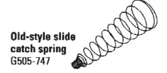
| Function | New-Style Replacement Parts | When Re | placing These Old-Styl | e Parts |
|---|---|---|---|---|
|
D30, D40,
D44, D55, |
SLIDE CATCH SPRING |
C303-009
Slide & Rollers ↓ |
C503-315
Slide Catch ↓ |
G505-747
Slide Catch Spring ↓ |
| D73, D85 | SLIDE CATCH | Ord | er These New-Style Pa | arts |
| SLIDE CATCH |
C303-006
Slide & Rollers C604-187 Slide Catch C604-191 Side Catch Spring |
C604-187
Slide Catch C604-191 Slide Catch Spring |
C604-187
Slide Catch C604-191 Slide Catch Spring |
| Function | New-Style Replacement Parts | When Re | placing These Old-Styl | e Parts | ||
|---|---|---|---|---|---|---|
| D53 | SLIDE CATCH SPRING C604-188 |
C303-009
Slide & Rollers ↓ |
C503-316
Slide Catch ↓ |
G505-747
Slide Catch Spring ↓ |
||
| SLIDE CATCH | Ord | er These New-Style P | Parts | |||
| SLIDE CATCH |
C303-006
Slide & Rollers C604-188 |
C303-006
Slide & Rollers C604-188 |
C303-006
Slide & Rollers C604-188 |
|||
|
Slide Catch
C604-191 Side Catch Spring |
Slide Catch
C604-191 Slide Catch Spring |
Slide Catch
C604-191 Slide Catch Spring |
||||
|
C303-006
SLIDE & RÖLLERS |
||||||

D-SERIES CYLINDERS
Schlage locks are provided with cylinder units precision built to extremely close tolerances and the highest standard of accuracy. Phospher bronze springs, nickel silver keys and pins are used throughout the Schlage offering. The best combination of materials is used to ensure the manufacture of cylinders with ease of operation and long wear.
Cylinder Units
| Number | Description |
|---|---|
| 23-001 | 6 Pin unit, Standard |
| 21-002 | 6 Pin unit (21/8" - 21/2" doors) |
| 23-003 | 6 Pin indicator unit |
| 23-003-098 | Individual unit (21/8" - 21/2" doors) |
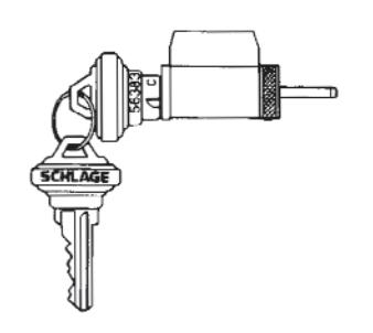
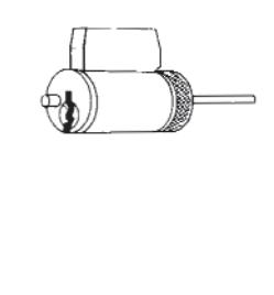
Hotel Function Indicator Cylinder 23-003
Cylinder Parts
| Number | Description |
|---|---|
| 33-006 | Cylinder plug, 6 pin |
| 33-216 | Cylinder plug, indicator, 6 pin |
| A201-849 | Body, 6 pin |
| C503-767 | Driver for 23-003, 24-001 |
| C503-347 | Bar for 24-001 |
| C603-098 | Disc for 23-003, 24-001 |
| C604-106 | Bar, driver for 23-003 |
| C604-107 | Bar for 23-003-098 |
| C604-243 | Bar, driver for 23-001 |
| C604-144 | Indicator spring |
| C604-371 | Indicator for 23-003 |
| C603-195 | Obstruction pin for 23-003 |
| C503-113 | Tumbler pin springs |
| C503-115 | Retainer cap Springs |
| C503-116 | Retainer cap Pins |
| C503-118 | Retainer cap |
IMPORTANT: Use graphite or similar material for cylinder lubrication only. Under no circumstance should any other type of material be introduced into the cylinder.

D-SERIES LATCHES & STRIKES
D-Series latches are adjustable for flat or beveled edge doors. Latches and strikes are available in brass, bronze, or chrome finishes.
All D-Series latches have throw and 1" housings, unless otherwise noted.
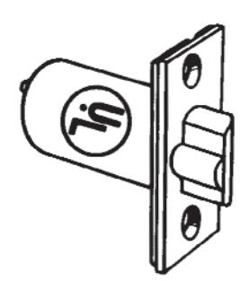
Square Corner Latch Deadlatch
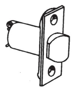
Square Corner Latch Springlatch
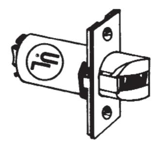
Fire Door Latch
| Backset | Description | Deadlatch | Springlatch | ||
|---|---|---|---|---|---|
| 23/4" | 11/8" x 21/4" square corner | 14-047 | - | ||
| 11/8" x 21/4" square corner | 14-019 | 14-001 | |||
| 23/4" | 11/8" x 21/4" Marine latch | 13-019 | 13-001 | ||
|
11/8" x 21/4", 3/4" Throw,
Fire door latch |
14-042 | - | |||
| 23/4" | 11/8" x 21/4", square corner | 14-028 | 14-010 | ||
NOTE: Hollow metal doors must be properly reinforced for latch support
Strikes
All Schlage strikes are furnished complete with screws. The standard D-Series strike has a 1% lip and is furnished with a black plastic dust box.
| Number | Description | Lip Length |
|---|---|---|
| 10-013 | 11/8" x 2 3/4", Standard | 11/8" |
| 10-016 | 11/8" x 2 3/4", Deep box | 11/8" |
| 10-019 | 11/8" x 2 3/4", Marine box | 11/8" |
| 10-025 | 11/8" x 4 7/8", ANSI | 13/16" |
| 10-042 | 11/6" x 4 1/6", Electric Latch Release | - |
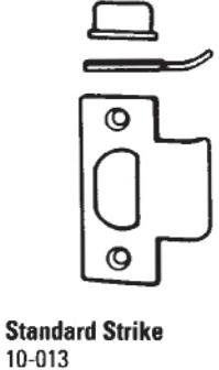
11/8" x 2 3/4" x 3/32"
ANSI Strike 10-025 11/4" x 4 7/4" x 3/32"
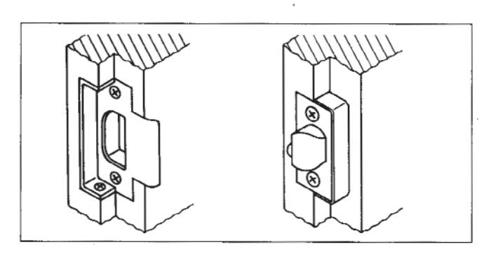
Rabbeted Latch and Strike Kit 39-030
This kit adapts square corner latches and strikes for ½" rabbeted door and frame preparations.

ELECTRIFIED LOCKS
Certifications:
Schlage heavy duty cylindrical D-Series locks are rated for both fire and electrical single point locking applications on labeled openings by Underwriters Laboratories U.L. 119X.
Electrical Requirements:
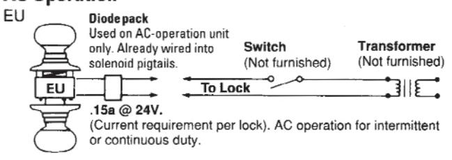
Electrically locking: Amps .15; Volts 24 AC only. Electrically unlocking: Amps .15; Volts 24 AC. Amps .35; Volts 24 DC.
Functions
D80PDEL
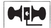
Electrically Locked
Auxiliary latch deadlocks latchbolt when door is closed. Outside knob continuously locked electrically until unlocked by key, switch for power failure. Inside knob always free for immediate exit.
D80PDEU
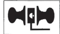
Electrically Unlocked
Auxiliary latch deadlocks latchbolt when door is closed. Outside knob continuously locked until unlocked by key or electric current. Inside knob always free for immediate exit.
Typical Wiring Diagram
AC Operation
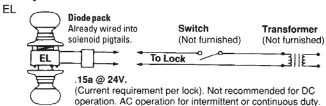
AC Operation
DC Operation
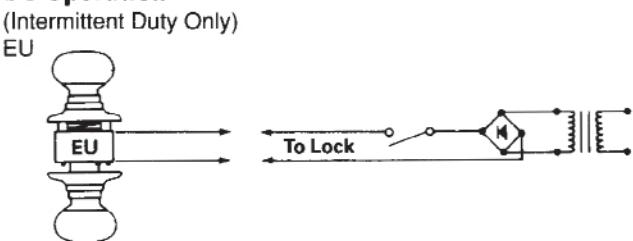
For EU Specify AC or DC current when ordering.

INTERCHANGEABLE CORE
Schlage Interchangeable Core cylinders allow the immediate rekeying of a lock without the time and expense of re-pinning cylinders. The core is removable by rotating a Control Key 15° and pulling out the core. The replacement core is installed with
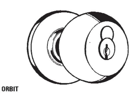
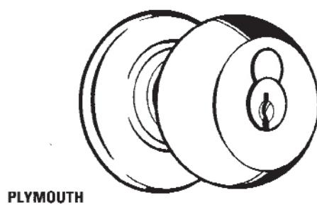
the same rotation of a control key and inserting the core into the knob housing. Available for all D-Series keyed functions in Plymouth, Orbit and Tulip knobs. Existing installations can be retrofit without removing the lock from the door.
Interchangeable Core Parts
| Number | Description |
|---|---|
| 04-030 | Knob, driver, retainer |
| 04-031 | Knob only |
| 04-033 | Driver, retainer |
| 04-034 | Knob, core, driver, retainer |
| 23-030 | Interchangeable Core |
| 33-058 | Plug, Interchangeable Core |
| 35-056 | Control key, blank |
| 48-056 | Control key, cut |
| C604-333 | Driver bar |
| C603-569 | Retainer |
| C503-115 | Spring, cap |
| C603-347 | Pin, cap |
| C503-118 | Cap |
| C603-956 | Arm, unlocking |
| C603-967 | Control pin |
| C603-964 | Actuating pin |
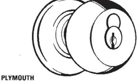
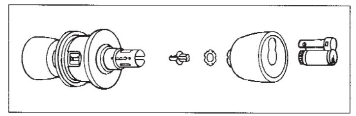
Retrofit Kit 04-034
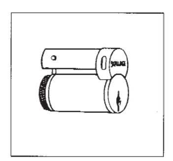
Interchangeable Core 23-030
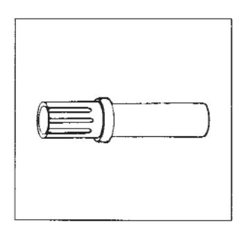
Installation Tool M504-142 Order as needed.
INTERCHANGEABLE CORE
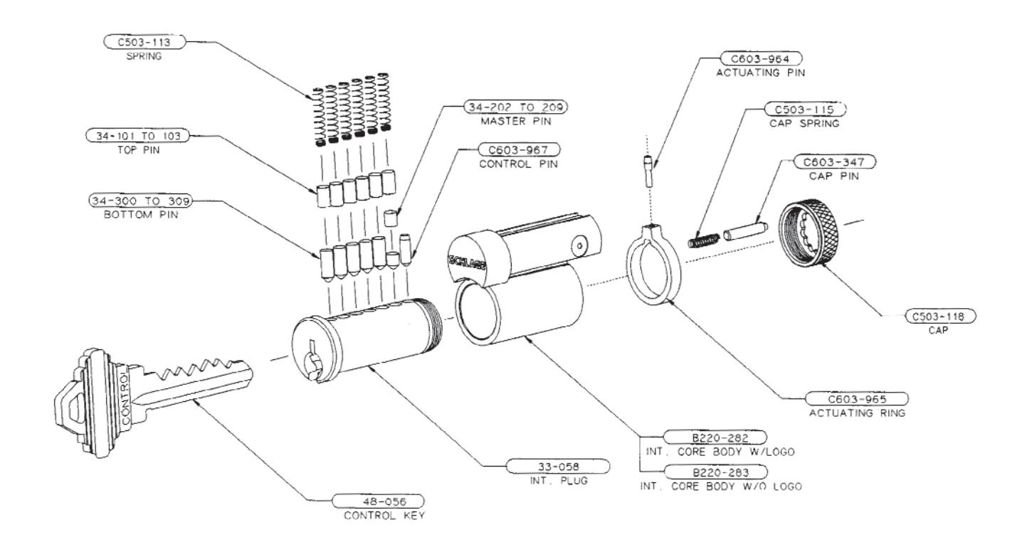
INTERCHANGEABLE CORE 23-030 W/LOGO 23-031 W/O LOGO

D-SERIES DESIGNS
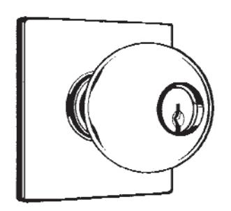
Comet
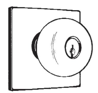
Hanover
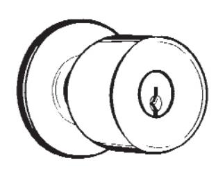
Luna
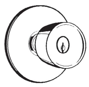
Magnolia
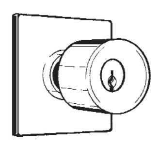
Meteor
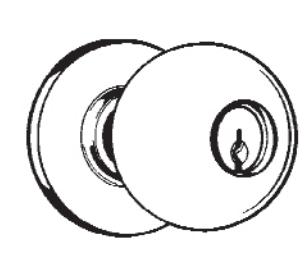
Orbit
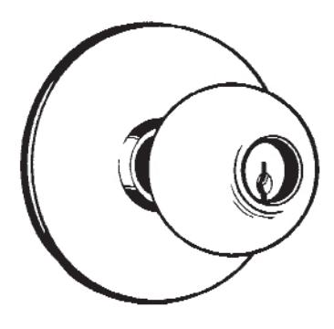
Planet
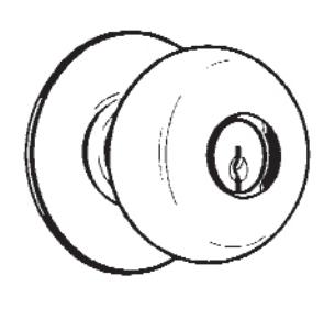
Plymouth
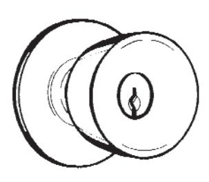
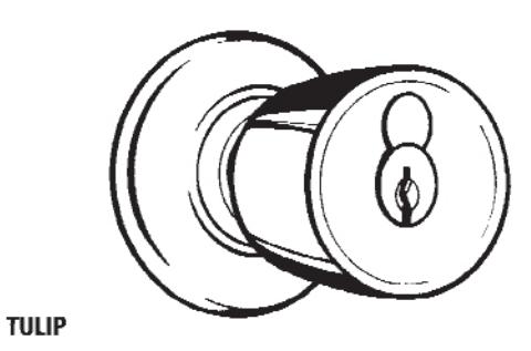
Tulip
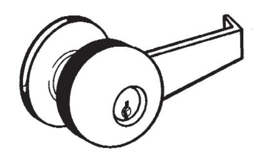
Retrofit Lever
This lever converts D-Series Orbit, Plymouth, and Tulip design 04-032 knob locks into lever handle locks. To install the retrofit lever, remove the knob from the lock, and replace the knob sleeve with our 04-032 lever kit.

Finishes
Schlage finishes are durable, top quality finishes obtained by the careful processing of solid brass, bronze, stainless steel, or other materials. Where required, a protective clear coating is electrostatically applied and cured under high temperature. It is important that climatic conditions and usage be taken under consideration when selecting finishes. This is especially true in areas subjected to strong corrosive vapors, humid climate, or sea air which, in a short time, may have a damaging effect on metal finishes.
The longevity and preservation of the finish appearance is determined by base metal and finishing process. Clear protective coating or other organic finishing applications may require different methods of cleaning and care. As an example, non-clear coated finishes should not be cleaned with soaps or any solvents; organically coated surfaces should periodically be cleaned with a mild, non-abrasive soap and buffed lightly with a clean cloth. The type of base metal and fishing techniques must be considered when applying any cleaning or preservative method. Contact the Schlage Technical Services Department for further information on the care of finished hardware.
In some instances, for customer convenience, the most appropriate BHMA finish symbols are used to indicate similarity of appearance, regardless of base metal or finishing process. Finish numbers in the 600 Series are the BHMA (Builders Hardware Manufacturers Association) industry standard. The nearest old U.S. equivalent code designations are shown in parenthesis.
| Symbol | Description |
|---|---|
| 605 (3) | BRIGHT BRASS, Clear coated |
| 606 (4) | SATIN BRASS, Clear coated |
| 611 (9) | BRIGHT BRONZE, Clear coated |
| 612 (10) | SATIN BRONZE, Clear coated |
| 613 (10B) | OIL RUBBED BRONZE, Oxidized satin bronze, oil rubbed, no coating |
| 625 (26) | BRIGHT CHROMIUM PLATED, No coating |
| 626 (26D) | SATIN CHROMIUM PLATED, No coating |
| 630 (32D) | SATIN STAINLESS STEEL, No coating |
Lubrication
D-Series lock mechanisms are designed for durability and seldom need servicing. During assembly, those points of contact which require lubrication for ease of operation are given an application of high quality petroleum base grease. A touch of graphite is applied to the pin tumbler plug during assembly of the cylinder unit. No further servicing should be required for an extended period except where locks are subjected to heavy traffic. Also, if located in particularly dusty or dirty areas, the original grease may become contaminated, resulting in a slow or otherwise unsatisfactory operation. The case mechanism should then be cleaned in a noncorrosive petroleum solvent and re-lubricated. Graphite should be applied to the cylinder unit by blowing a small quantity into the keyway.
NOTE: Precautionary measures according to solvent manufacturers instructions should always be followed.
Tactile Warning
Tactile warning is achieved by knurling or applying an abrasive coating to a knob or lever. This is the means of identifying hazardous areas, such as electrical closets and mechanical equipment for the visually impaired.
Knurling is available on D-Series locks for Comet, Planet, Plymouth, and Orbit knob designs.
Schlage D-Series Plymouth and Orbit designs are offered with abrasive coating.
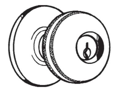
Knurling
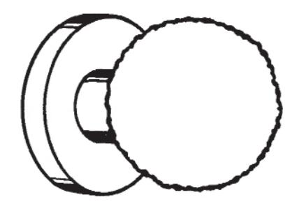
Abrasive Coating

INSTALLATION
Installation Tools & Kits
Boring jigs and tools are designed to provide fast and accurate lock installation. Complete kits, contained in a heavy gauge metal box, or individual tools can be ordered for preparing doors and jambs for Schlage products.
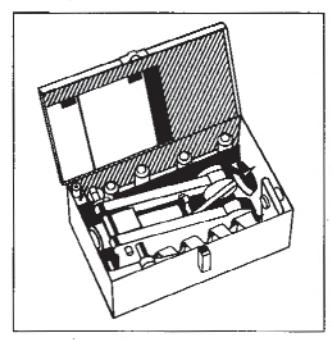
Installation Kit
For A, D, or F locks. Adjustable for For A, B, D, F, and H Locks. 2 \(^3\%\)", 2 \(^3\%\)" 5" backsets. Removable Adjustable for 2 \(^3\%\)" and 2 \(^3\%\)" bushing adapter for \(^3\%\)" latch hole. backsets. Designed for special For door thickness 1 \(^3\%\)" to 2 \(^3\%\)". high-speed hexagonal shank
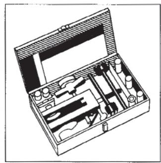
Installation Kit
For A, B, D, F, and H Locks. Adjustable for 2 % a" and 2 ¾" backsets. Designed for special high-speed hexagonal shank boring bits and equipped with an adapter to form an integrated unit for boring doors 1 5/16" to 1 15/16" thick.
| Number | Description | |
|---|---|---|
| 40-056 | Boring jig | |
| 40-015 | ⅓" Boring bit | |
| 40-018 | 1" Boring bit | |
| 40-024 | 21/a" Boring bit | |
| 40-029 | Strike marking chisel, full lip | |
| 40-030 | Strike marking chisel, full lip | |
| 40-032 | Latch marking chisel; B, D, H | |
| 40-035 | Strike locator, 7/8" | |
| 40-036 | Strike locator, 1" | |
| 40-041 | 4" Bit extension | |
| 40-050 | Tool box | |
| M507-347 | Socket wrench | |
| 40-012 | Boring jig | |
| 40-016 | 1/8" Boring bit | |
| 40-019 | 1" Boring bit | |
| 40-025 | 21/8" Boring bit | |
| 40-028 | 21/8" Boring bit | |
| 40-029 | Strike marking chisel | |
| 40-030 | Strike marking chisel | |
| 40-031 | Latch marking chisel | |
| 40-032 | Latch marking chisel | |
| 40-035 | Strike locator | |
| 40-036 | Strike locator | |
| 40-039 | Boring bit adapter | |
| 40-042 | Backset peg | |
| 40-049 | Tool box | |
| M504-265 | Jig replacement bushing |
Long Backsets
Backsets 5" and over require extension links. D-Series locks with long backsets are normally furnished with 1% "faceplate and 1" housings. Links installed in 1" latch holes require one A501-567 sleeve to join latch and link. Backsets over 5" require an additional sleeve placed "from lock chassis. Information on long backsets other than 5" is available on request.
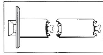
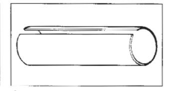
43-005 5"
Sleeve A501-567
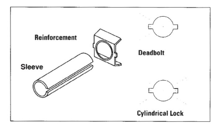
Reinforcement Kit
Schlage 37-001 reinforcing unit is used to reinforce and help prevent the collapse of hollow metal doors when locksets are tightly mounted.
This kit should be used with long backsets for A, B, or D lock installations in hollow metal doors to prevent lateral movement of the latchbolt.
Spanner Wrench
M504-310
For tightening inside threaded roses and depressing knob catches of "A" or "D" locks.
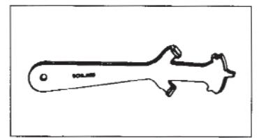

HOW TO REMOVE AND REPLACE D-SERIES CYLINDER KNOBS
Outside Knobs - Functions D53, 55, 60, 80, 82 (Outside & Inside), 85.
To Remove Knob:
- Insert key into cylinder, and place pointed end of spanner wrench into hole in knob sleeve on side facing latch retracter or latchbolt
- Turn key approximately one-quarter turn to the right while exerting pressure on wrench until knob catch depresses. Pull off knob.
To Replace Knob:
- 1. With key partially removed and keyway in vertical position, slide knob onto spindle until it stops against knob catch.
- 2. Insert key fully and turn key (but not the knob) slowly to the right until knob catch can be depressed with spanner wrench. Push knob into place until catch is engaged. Pull on knob to make sure that catch is engaged.
Outside knobs - Functions D66, 70, 72, 73, 76.
NOTE: Outside cylinder of D66 must be fully installed (with key removed).
To Remove Knob:
- 1. Insert key and turn to the left as far as it will go.
- Insert pointed end of spanner wrench through hole in knob sleeve on side facing latch retracter or latchbolt.
- Exert pressure on wrench while turning key slowly to the right until knob catch depresses. Pull off knob.
Functions D60 (Inside), 66, 70, 72, 73, 76
- 1. Use a flat tip screwdriver (1/4" wide tip), and insert into chassis far enough to engage key spindle. Rotate screwdriver to the left until key spindle stops turning. Remove screwdriver.
- 2. With key partially removed and keyway in vertical position, slide knob onto spindle until it stops against knob catch.
- 3. Insert key fully and turn key (but not the knob) slowly to the right until knob catch can be depressed with spanner wrench. Push knob into place until catch is engaged. Pull on knob to make sure that catch is engaged.
- 4. When knob is properly installed, the key can be withdrawn after one complete turn to the right.
- NOTE: If lock is out of timing and key cannot be removed in the correct position, with the key still inserted, remove knob from spindle, and repeat steps for replacement.

INSTALLATION INSTRUCTIONS
1. MARK DOOR
Mark height line (center line of latchbolt) on edge of door. Suggested height from floor 38". Mark center point of door thickness. Position center line of template on height line. Hold in place and mark center point for 21/8" hole.
Mark center for 1" hole at center point on height line.
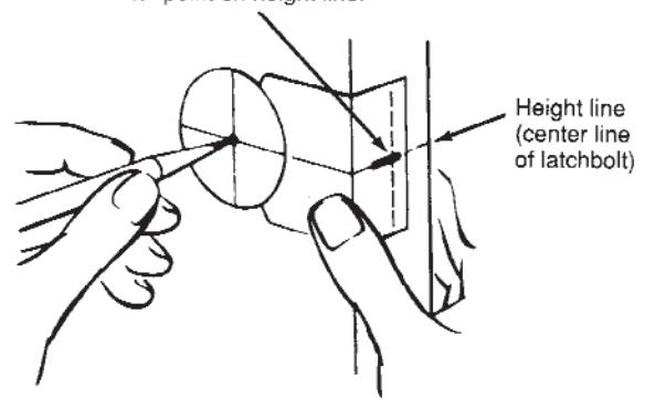
2. BORE TWO HOLES
Bore a 21/4" hole from both sides of door (to avoid splintering or otherwise damaging door).
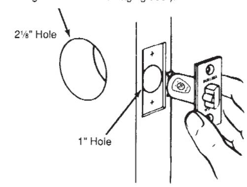
Bore a 1" hole straight into door edge to intersect with center of " hole.
Use latchbolt faceplate to pattern for cutout. Front should fit flush with door surface. Install latch with screws provided.
3. INSTALL STRIKE
Mark vertical line and height line on jamb exactly opposite center point of latch hole. Bore two 1" holes " deep in jamb on vertical line " above and below height line. Clean out hole and install strike.
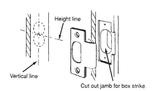
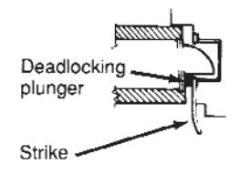
Deadlocking plunger on latchbolt stops against strike, preventing forcing when door is closed.
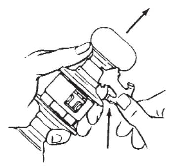
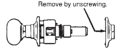
4. REMOVE INSIDE TRIM
Insert pointed end of spanner wrench through hole in knob sleeve on side facing latch retractor. Depress knob catch and slide knob off spindle.
INSTALLATION INSTRUCTIONS
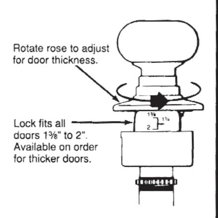
5. ADJUST ROSE
Adjust lock to fit door thickness by rotating outside rose until correct door thickness appears above edge of housing and it is engaged with ratchet.
6. INTERLOCK UNITS
Latch unit must be in place before installing lock. Be sure lock housing engages with latch prongs and retractor interlocks with latch bar.
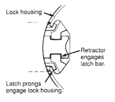
Caution -- Do not attempt to mount lock unit with door closed.
7. ATTACH TRIM
Slip inside rose over spindle and screw on to threads. Tighten firmly with spanner wrench.
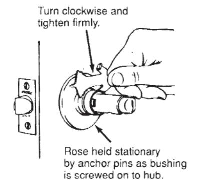
8. REPLACE KNOB
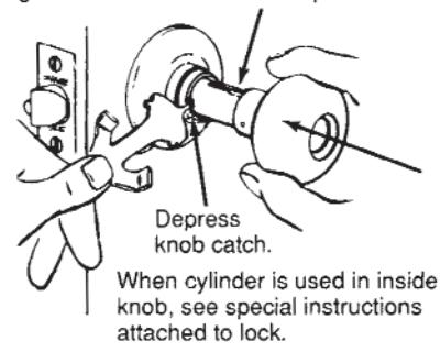
Slide knob on spindle. Depress knob catch and push knob into position. Pull knob to test fastening of catch. When properly installed, both knobs should operate freely.
Before sliding knob on spindle, line up lug in knob shank with slot in spindle.
9. TO CHANGE LOCK HAND
Pin tumbler cylinders are factory assembled in knobs for right or left hand doors as ordered. If necessary to change the hand of a lock so that cylinder is right side up, see following instructions.
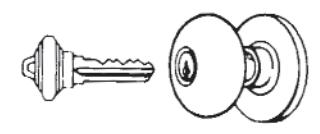
RIGHT WAY
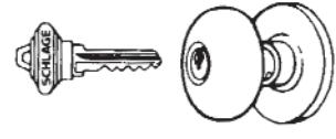
WRONG WAY
9A. STANDARD CYLINDER
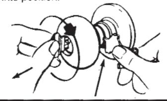
Insert pointed end of spanner wrench, or small nail, in the outside knob sleeve on side facing latchbolt. Exert pressure and turn key slowly until knob catch depresses; then pull off knob. Turn knob over. With key partially removed from cylinder, replace knob onto spindle. Slide knob up to knob catch. Insert key and turn key one-quarter turn to right, depress knob catch and push knob into position.
9B. INTERCHANGEABLE CORE CYLINDER
Follow steps in 9A for removing knob, CORE MUST NOW BE REMOVED FROM KNOB BEFORE REPLACING ON LOCK. Insert control key and turn 15° to the right until action stops. Pulling on key will now extract core from knob.
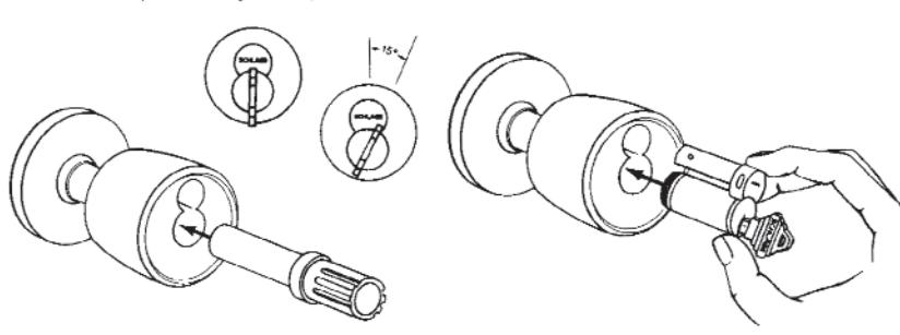
Turn knob over and replace knob on spindle. Slide knob up to knob catch. Insert long end of installation tool into knob until it engages driver. Turn tool one-quarter turn to right, depress knob catch and push knob into position. With control key fully inserted, push core into knob housing, rotate key 15° to the right and insert core completely. Rotate key back to upright and remove control key.

KEYING
Key Array Chart
The Schlage Masterkey Department determines and makes the final decision in the selection and use of Key Sections. Keys and cylinders other than C, CE, E, EF, and F are restricted and authorized by factory only. Other keyways are available for use within limited geographical areas. Allocation of these special keyways is based on need and extent of the final system. Priority is given to sensitive industries that require large numbers of cylinders and families of key sections to satisfy their keying requirements.
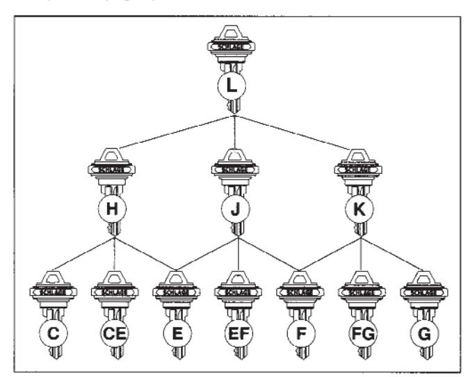
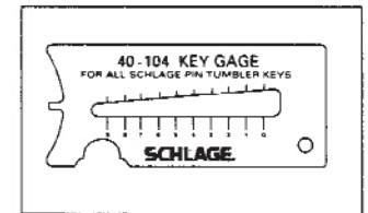
Key Gauge 40-104
Order the Schlage key gauge to accurately measure the depth of key cuts. Specify quantity and number.
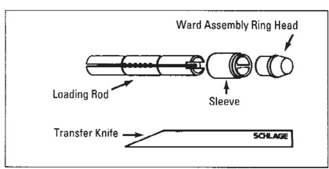
Cylinder Body Loading Tool 40-116
A compact, precision tool for loading top pins and springs and installation of ward rings into grooves of a warded cylinder plug. Furnished with complete assembly instructions.
Pin Tumbler Keys
All Schlage locks come with two nickel silver keys as standard, embossed with our company logo. The nickel silver alloy from which all Schlage keys are made provides the base for accuracy in cutting and long cylinder wear.
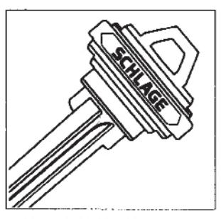
Embossed Both Sides 35-100 (5 pin standard) 35-101 (6 pin)
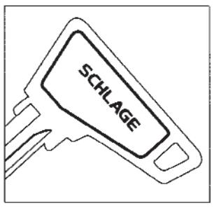
Access Bow 35-143 (5 pin*) 35-144 (6 pin) *Available in C, E, F & CE only
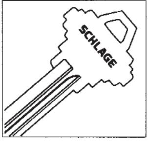
Stamped One Side 35-120 (5 Pin) 35-121 (6 Pin)
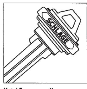
Hotel Emergency Key 35-102 (6 Pin)
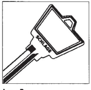
Large Bow 35-140 (5 Pin) 35-141 (6 Pin)
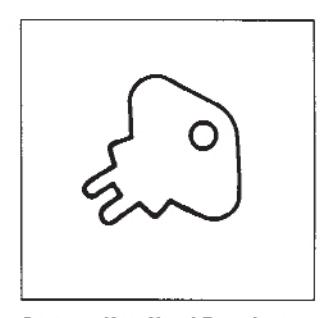
Spanner Key, Hotel Function 35-251

Ordering Procedures
To order Schlage products, descriptive data should be in the same sequence shown. Ordering examples are also shown to assist in proper sequencing.
| Out | side | Ins | side | Dr | Door Hand | ||||||||||||||
|---|---|---|---|---|---|---|---|---|---|---|---|---|---|---|---|---|---|---|---|
| Oty | Product | Des | Fin | Des | Fin | Thk | RH | LH | RR | LR | BS | Latch | Strike | Dim | Detail | ||||
| 1 | 3 | 5 | 7 | 10 | 12 | ||||||||||||||
| 2 | 4 | 6 | 9 | 11 | 13 | ||||||||||||||
1. Quantity
2. Lock number or product
(accessories or parts)
3. Design: outside
4. Finish: outside
5. Design: inside
6. Finish: inside
7. Door thickness; for
non-standard thickness
such as 214 = 2 1/4"
8. Door handing
9. Backset: 234 = 2 3/4", 005 = 5"
backset link required
10. Latches: Use this area for listing
non-standard latches, per backset.
11. Strike: Use this area for listing
non-standard strikes.
12. Dimension: Use this area for strike
lip lengths, padlock shackle length, mortise
cylinder length, etc. 118 = 1 1/8", 138 = 1 3/8", etc.
13. Detail: Use this area for keying detail and/or any special instructions relating to the ordered item,
such as lead lining, knurling, etc.
Ordering example:
| Outside | Inside | Dr | Door Hand | ||||||||||||
|---|---|---|---|---|---|---|---|---|---|---|---|---|---|---|---|
| Ωty | Product | Des | Fin | Des | Fin | Thk | RH | LH | RR | LR | BS | Latch | Strike | Dim | Detail |
| 50 | D53PD | HAN | 613 | 50 | 10-025 | 101AA-125AA | |||||||||
| 2 | D80PD | ORB | 626 | 214 | 2 | Knurled O/S knobs | |||||||||
| 1 | D80DEU | PLY | 605 | 1 | 334 | 24VA.C. | |||||||||
| 10 | 04-007 | TUL | 613 | Open knob | |||||||||||
| 10 | 10-013 | 626 | 200 | 2" Lip | |||||||||||
The reverse side of Schlage's order acknowedgement copy contains a full list of terminology used in coding orders for our data processing system.
Limited Warranty
Schlage Lock Company (the "Company") warrants to the original purchaser that the products manufactured by it (the "Product") to be free of defects in material and workmanship. Provided: (i) The Company has been notified within one year of purchase date and been given the opportunity of inspection by return of any alleged defective Product to the Company, or its authorized distributor, at the address specified herein, free and clear of all liens and encumbrances, transportation prepaid, accompanied by the statement of defects and proof of purchase; and (ii) The Product has not been modified, abused, misused, or improperly installed, maintained and/or repaired during such period; and (iii) Such defect has not been caused by corrosion or ordinary wear and tear.
The Company makes no other warranty, and all implied warranties including any warranty of merchantability or fitness for a particular purpose are limited to the duration of the expressed warranty period as set forth above.
The Company's maximum liability hereunder is limited to the purchase price of the product.
In no event shall the company be liable for any consequential, indirect, incidental or special damages of any nature arising from the sale or use of this product, whether in contract, tort, strict liability or otherwise.
Note: Should the Product be considered a consumer product as may be covered by the Magnusson Moss Federal Warranty Act, please be advised that: (1) Some states do not allow limitations on incidental consequential damages or how long an implied warranty lasts so that the above limitations may not fully apply; (2) This warranty gives specific legal rights and a buyer may also have other rights which may vary from state to state.
For warranty service and shipping instructions, contact the Schlage Lock Company:
Technical Services Department 2401 Bayshore Boulevard San Francisco, California 94134 (415) 330-5600
The Schlage Lock Company reserves the right to make changes in designs and specifications or to make additions or improvements on its products without notice and without incurring any obligation to incorporate them on products previously manufactured. The Schlage Lock Company is not responsible for any modification, addition, or alteration to our products by others.

NOTES

NOTES
About Allegion
Allegion (NYSE: ALLE) creates peace of mind by pioneering safety and security. As a $2 billion provider of security solutions for homes and businesses, Allegion employs more than 7,800 people and sells products in more than 120 countries across the world. Allegion comprises 23 global brands, including strategic brands CISA®, Interflex®, LCN®, Schlage® and Von Duprin®.
For more, visit www.allegion.com .