Roton Installation Instruction ETW – 75009017-Rev-032019
Open the original PDF document
View PDF

ROTON ELECTRIC MODIFICATION PART NO: 75009017 ROTON MODEL: 780-111, -112, -124, -224, -226 REVISION: 03/20/19
HAGER Companies, 139 Victor Street, St. Louis, MO 63104 (800) 325-9995
CONCEALED ETW – Electric Through Wires
Door and Frame Preparation
For grout filled frame, install a Mortar Box (HAGER 430). Failure to do so will void the hinge warranty. Refer to Table 2 and Figures below for your particular ROTON Hinge model.
- 1. Drill a 1/2" (5/8" max for Quick Connects) diameter access hole in both the frame rabbet and the door edge for a Concealed Hinge or in the frame and the door face for a Full Surface hinge at the proper location for the wire leads. (12-wire, ETW only, model Concealed Hinges will require two drilled holes in both the frame and door.)
- 2. After drilling, deburr the holes to prevent damage to the wire leads.
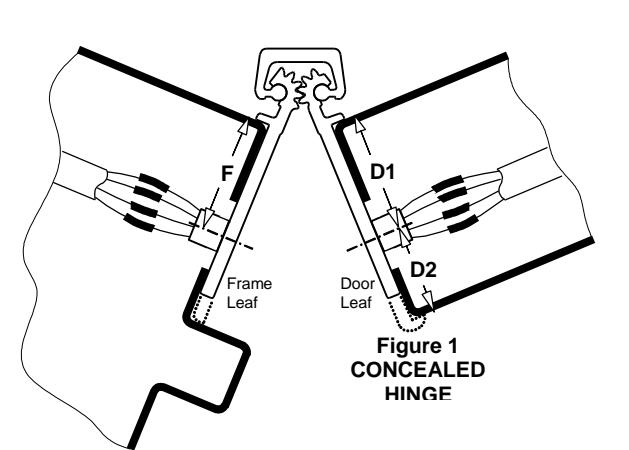
Table 2
|
HINGE
MODEL |
TYPE | F | D1 | D2 | |
|---|---|---|---|---|---|
| 780-111 | Concealed | 15/16" | 13/16" | - | |
| 780-112 | Concealed | 15/16" | 15/16" | - | |
| D2 | 780-124 | Concealed | 15/16" | - | 7/8" |
| 780-224 | Concealed | 15/16" | - | 7/8" | |
| Figure 1 | 780-226 | Concealed | 15/16" | 15/16" | - |
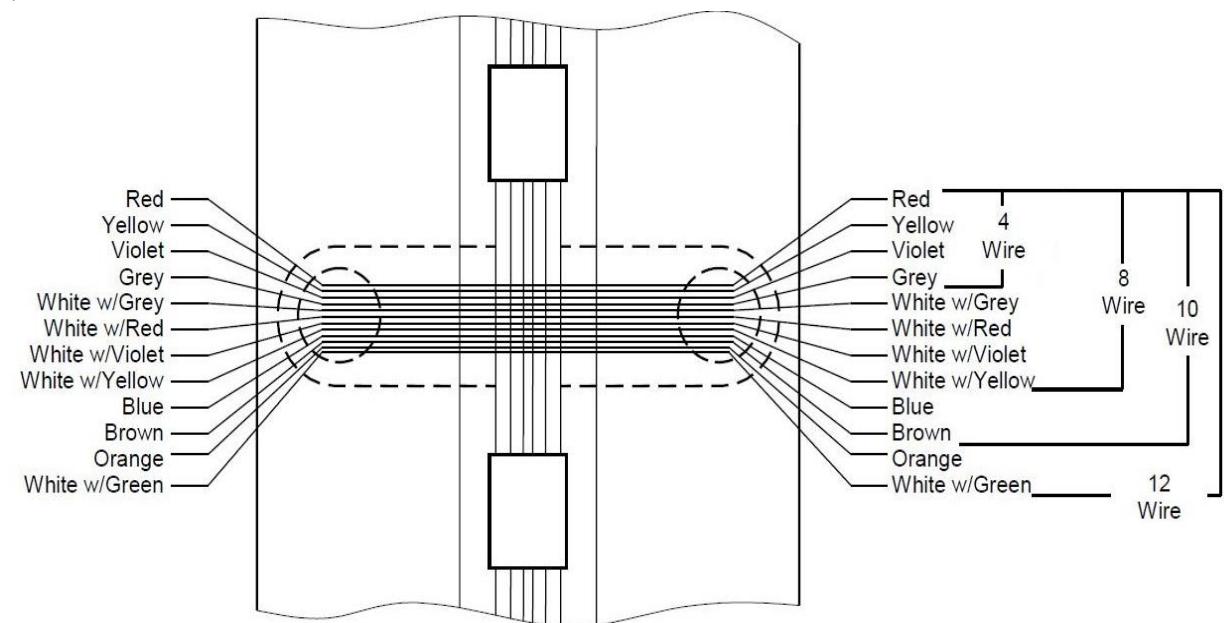
MAXIMUM ELECTRICAL Figure 2 RATING CONTACT
Volts: 30V dc/ac Amperes: 3.5A Continuous 16A Pulse (300ms)
Recommended: For current ratings greater than 1.0A, use two or more wires in parallel. Make sure same colored wires are connected properly on both sides of hinge.

ROTON ELECTRIC MODIFICATION PART NO: 75009017 ROTON MODEL: 780-111, -112, -124, -224, -226 REVISION: 03/20/19 HAGER Companies, 139 Victor Street, St. Louis, MO 63104 (800) 325-9995
EMN – Concealed Magnetic Switch
Door and Frame Preparation
For grout filled frame, install a Mortar Box (HAGER 430). Failure to do so will void the hinge warranty.
- 1. Prepare the door and frame for installation using the standard installation instruction sheet furnished with the hinge, but do not attach the hinge at this time.
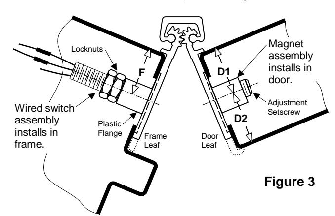
- 2. Locate the wired switch assembly. Peel the adhesive liner from the face of the flange. Attach it in the counter bore on the back of the hinge leaf that will be mounted to the frame . See Figure 3.
-
3. Locate the magnet assembly. The magnet is preset from the factory to activate properly for a metal frame and a metal square-edged door.
- For the following conditions, the magnet assembly must be adjusted using a 5/32" hex key:
- Metal door with a beveled edge on the hinge side turn the adjustment setscrew clockwise 1½ turn.
- Wooden door turn the adjustment setscrew counter-clockwise 1½ turn. Peel the adhesive liner from the face of the flange. Attach the magnet assembly in the counter bore on the back of the hinge leaf that will be mounted to the door . See Figure 3.
-
4. Drill a 3/4" diameter access hole in both the frame rabbet and the door edge at the proper location for the switch and magnet.
- If a shim is utilized in the installation of the hinge, drill a corresponding 3/4" diameter access hole in the shim also. If there is a gap in the shim where the switch or magnet is located, the gap must be no greater than 3/4" so as to provide support for the plastic flange.
- 5. After drilling, deburr the holes to prevent damage to the wire leads.
Installation
- 1. Attach the hinge to the door per the standard installation instruction sheet supplied with the hinge.
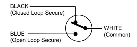
- 2. Connect the system wiring to the appropriate leads of the switch. See Figure 3. Insulate the bare end of any unused wires.
- 3. Carefully slide the wires back through the access hole making sure they are placed so they will not be cut or pinched as installation is completed. Attach the hinge to the frame per the standard installation instruction sheet supplied with the hinge.
- 4. Certain factors (frame thickness, door thickness, reinforcements, door material) can slightly affect the sensitivity of the reed switch after installation. Check the circuit to make certain the switch is opening and closing as desired. If necessary, turn the adjustment setscrew in or out to overcome these factors (see Door and Frame Preparation, Step 2). The door must be removed to adjust the magnet.
|
HINGE
MODEL |
F | D1 | D2 |
|---|---|---|---|
| 780-111 | 1" | 7/8" | - |
| 780-112 | 7/8" | 7/8" | - |
| 780-124 | 15/16" | - | 7/8" |
| 780-224 | 15/16" | - | 7/8" |
| 780-226 | 1" | 1" | - |
SWITCH INFORMATION Voltage Rating: 200VDC Current Rating: 500mA
Switch Function: SPST-NO
CLOSED LOOP SECURE
(Use black and white switch wires.) Closed Loop Secure hinges are wired so that when the door is closed (secured) the EMN switch is closed (passes current). When the door opens, an open circuit is detected as an alarm.
Open Loop Secure
(Use blue and white switch wires.) Open Loop Secure hinges are wired so that when the door is closed (secured) the EMN switch is open (does not pass current). When the door opens, a closed circuit is detected as an alarm.