ROFU 2435 Kit Electric Strike Installation Instructions
Open the original PDF document
View PDF

ROFU 2435 Kit Electric Strike Installation Instructions Field Reversible - Fail Safe Or Fail Secure
The 2435 Kit electric strike is designed for use with heavy duty mortise locks and cylindrical locksets. It comes with five different stainless steel (US32D) faceplates and it can be easily installed on wood, aluminum or metal jambs. It is field reversible from fail-secure to fail-safe and back again with the movement of two exterior screws.
Features
- Heavy duty stainless steel construction (US 32D)
- Vertical adjustments allow for alignment with a wide variety of mortise locks with offset latches
- Sliding keeper shim design for up to 1/8" (3mm) adjustment for misaligned frames
- Accommodates deadbolts up to 1"
- Field selectable for fail-safe or fail-secure
- Non-handed design fits either right-handed or left-handed doors
- Trim plate included
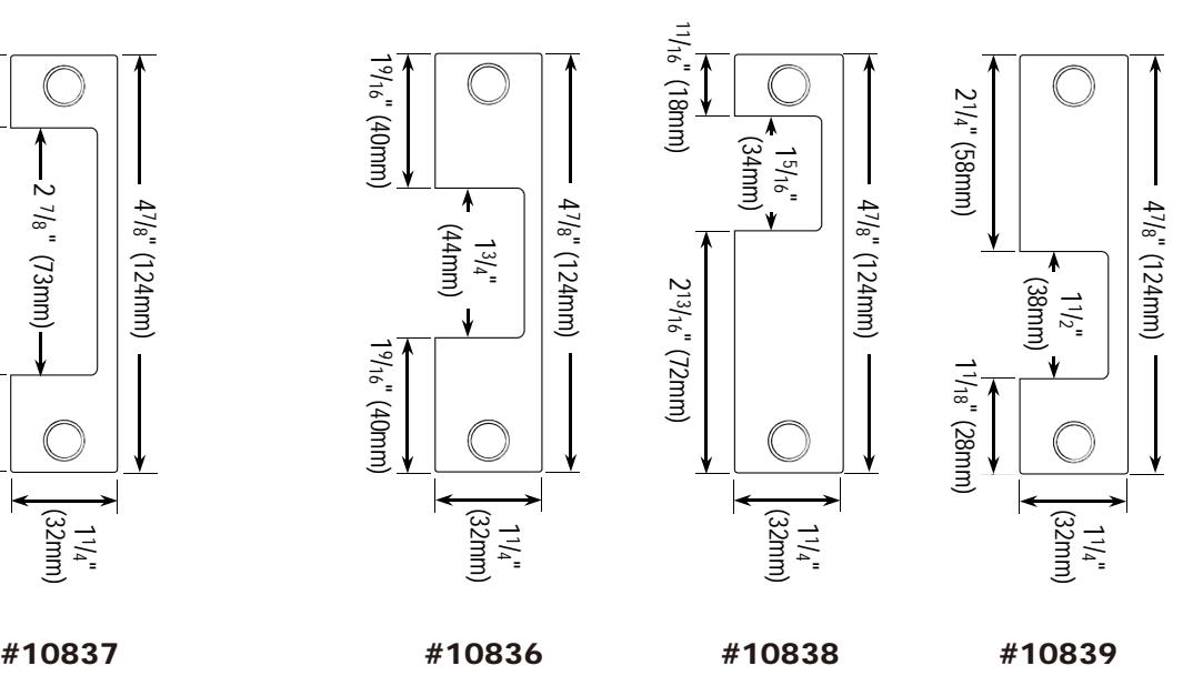
- Includes 5 different stainless steel faceplates
Specifications
| Operating Voltage | 12, 24 or 12/24 VDC |
| Voltage Tolerance | +- 15% |
| Current Draw | 250mA/12VDC, 150mA/24VDC |
|
Operating
Temperature |
14°F to 120°F |
| Humidity 0~85% non-condensing | |
| Latch Throw | 1" (25mm) max with 1/8" (3mm) door gap |
| Static Strength | 1000 lbs |
| Dynamic Strength | 33 ft-lbs |
| Endurance Rating | 1,000,000 cycles factory tested |
Dimensions
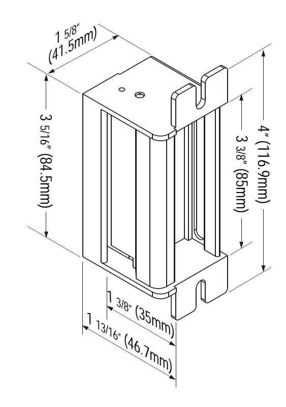
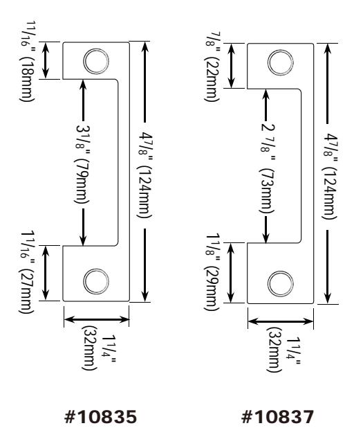
Deadbolt Latch Installation Latchbolt Installation
1
Note: If it is necessary to cut a hole in the frame, mounting tabs maybe required to strengthen the installation.
ROFU-2435KIT Published: 2016.09.13 Copyright © ROFU Security International Corp. All rights reserved.
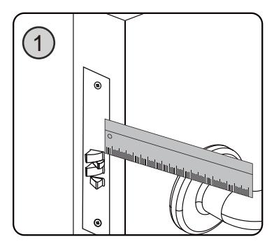
Measure latch position and mark on the frame.
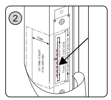
Attach the template to the frame and align the reference line with the marked line.
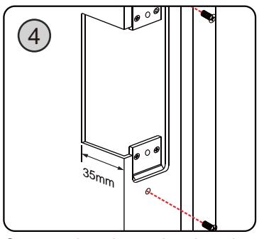
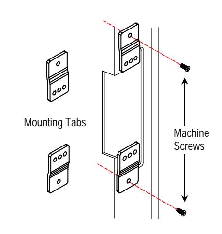
Fasten the mounting tabs to the frame.
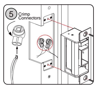
Connect the wires using the crimp connectors, then test the strike, ensure to give it correct voltage.
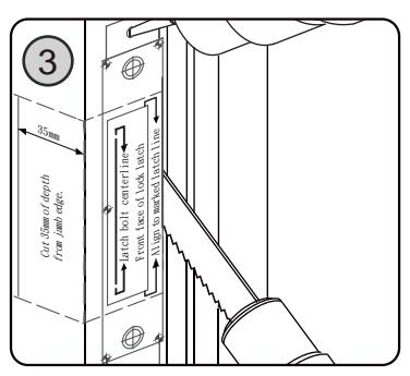
Drill and cut the frame according to the template.
Sticker Template Instruction
Butt Splice (IDC) Connector
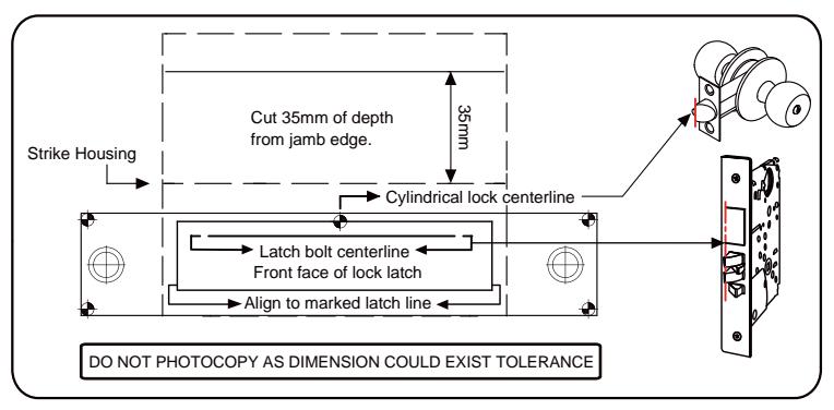
Refer to the supplied template. Verify lock compatibility and determine the reference line on the template.
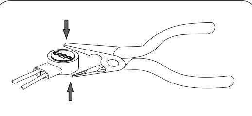
Place the wire inside the connector and use a crimp or pliers to press down on the head of the connector evenly.
We suggest using a LocTite product on the deadbolt box screw and the deadlatch ramp screw.
Mounting the Strike Using Mounting Tabs
The mounting tabs are only used for aluminum and metal door frames. This is commonly done when retrofitting door frames.
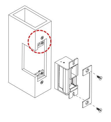
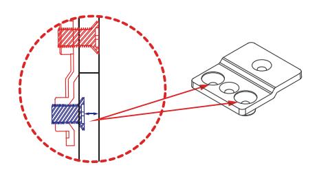
Drill holes according to the template for installation of the mounting tabs.
When installing, do not over-tighten the screws as small adjustments may be required to secure a snug fit for the door strike.
2
Copyright ROFU Security International Copy. All rights reserved. ROFU-429580T (substance 27:06.03.13.13.13.13.13.13.13.13.13.13.13.13.13
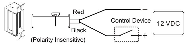
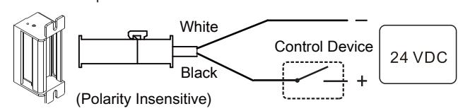
Wiring Instructions
12 or 24VDC Wiring Diagram
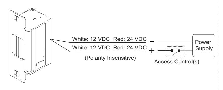
12/24 VDC Wiring Diagram
For 12VDC Operation:
For 24VDC Opration:
Mounting the Trim Plate
- 1 If the hole cut for the facepla is too large or is jagged, the trim plate can be mounted . over the hole to improve the appearance of the installation.
- . Screw the trim plate into to mounting holes at the top and bottom of the door strike using the included trim plate screws before installing the strike to the door frame. 2
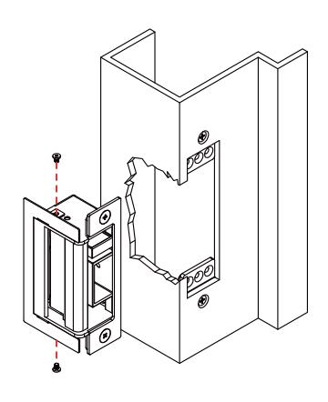
Electric Strike Adjustment
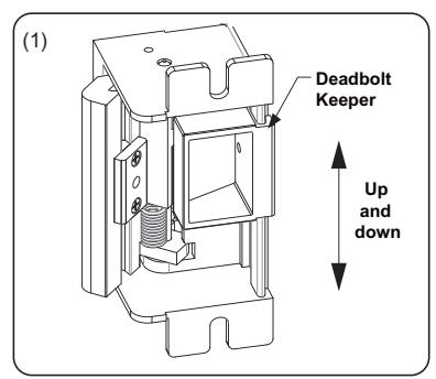
Adjusting Deadbolt Keeper
Extend the deadbolt, move the door close to the strike, and let the deadbolt touch the strike keeper. Mark deadbolt lines on the strike keeper. Open the door and adjust the deadbolt keeper up and down to align with the marked lines.
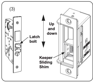
Adjusting Keeper Sliding Shim
To minimize door play, slide the keeper shim up and down to align with the latch bolt position.
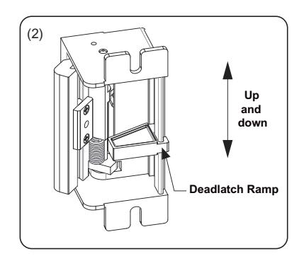
Adjusting Deadlatch Ramp
Move the door close to the strike. When the deadlatch touches the strike keeper, mark deadlatch lines on the strike keeper. Open the door and adjust the deadlatch ramp up down to align with the marked lines.
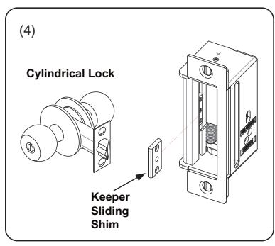
For cylindrical lock applications, remove the keeper sliding shim from the strike to ensure proper latch throw depth.
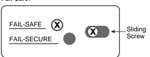
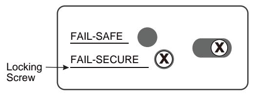
Changing Fail-Secure / Fail-Safe
- 1. Loosen and remove the locking screw.
- 2. Loosen and move the sliding screw to the desired setting, and replace/retighten both screws.

Fail-Secure:
ROFU Security International Corp. 10029 S. Tacoma Way, E-11 Lakewood, WA 98499 USA 1-800-255-7638 (1-800-ALL-ROFU) www.ROFU.com OrderEntry@ROFU.com