Profile Series v.G1.5 Cylindrical Lock Installation Instructions
Open the original PDF document
View PDFInstallation Instructions
For Profile Series v.G1.5
Cylindrical Lock

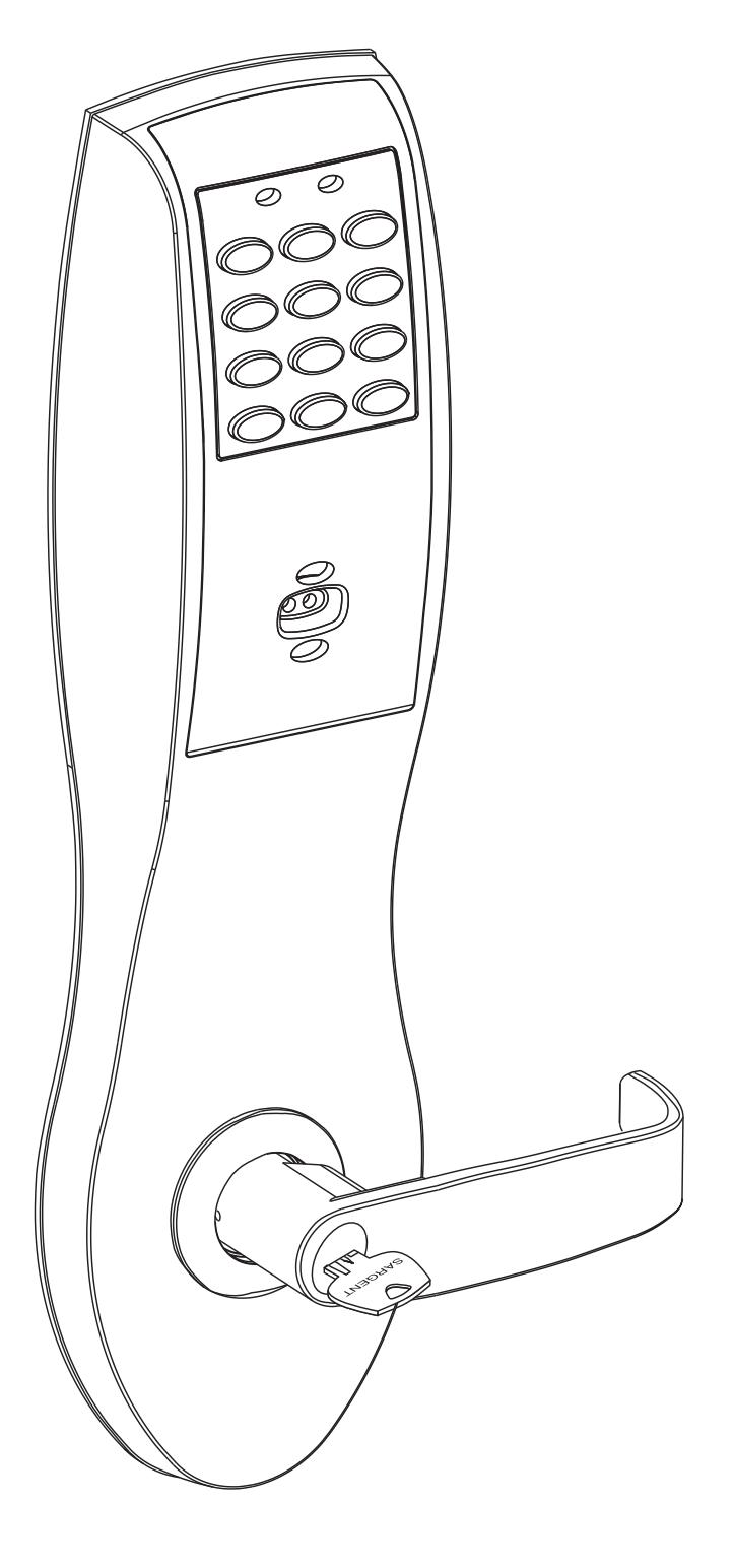
Table of Contents
Page
|
Warning
1 1 |
|---|
|
2
General Description1 |
|
Specifications1
3 |
|
Features1
4 |
|
Parts
Breakdown2–3 5 |
|
6
Installation Instructions |
|
6.1–Verify
Hand and Bevel of Door4 |
|
6.2–Door
Prep4 |
|
6.3–Frame
Preparation for Strike 5 |
|
6.4–Latchbolt
and Fire Stop Plate Installation 5 |
|
6.5–Lock
Installation6 |
|
6.6–Securing
the Lock in the Door7 |
|
6.7–Remove
Outside Lever Only 7 |
|
6.8–Installation
of Outside Escutcheon & Lever8 |
|
6.9–Inside
Escutcheon & Lever8 |
|
6.10–Hardwiring
Options |
|
6.10.A–Important
9 |
|
6.10.B–Installation
Notes 9 |
|
6.10.C–ElectroLynx® Connector
Notes9 |
|
6.10.D–Forced/Propped
Door Option (DM-) 10 |
|
6.10.E–Hard
Power & Remote Unlock (91-)11 |
|
6.10.F–Hard
Power and Remote Unlock (91-) |
|
with
Forced/Propped Door (DM-)12 |
|
6.11–Mount
Outside Escutcheon & Battery Installation 13 |
|
7
Operational Check14 |
|
8
Installation of RF Technology Lock (G1-TU, G1-TA, G1-TP) |
|
8.1–Installation
of the top through-bolt 14 |
|
8.2–Removal
procedure for Battery Keeper14 |

Warning: Changes or modifications to this unit not expressly approved by the party responsible for compliance could void the user's authority to operate the equipment.
This device complies with Part 15 of the FCC Rules. Operation is subject to the following two conditions: (1) This device may not cause harmful interference, and (2) this device must accept any interference received, including interference that may cause undesired operation.
Note: This equipment has been tested and found to comply with the limits for a Class B digital device, pursuant to Part 15 of the FCC Rules. These limits are designed to provide reasonable protection against harmful interference in a residential installation. This equipment generates, uses and can radiate radio frequency energy and if not installed and used in accordance with the instructions, may cause harmful interference to radio communications. However, there is no guarantee that the interference will not occur in a particular installation. If this equipment does cause harmful interference to radio or television reception, which can be determined by turning the equipment off and on, the user is encouraged to try to correct the interference by one or more of the following measures:
- Reorient or relocate the receiving antenna
- Increase the separation between the equipment and receiver
- Connect the equipment into an outlet on a circuit different from that to which the receiver is connected
- Consult the dealer or an experienced TV technician for help
This Class B digital apparatus complies with Canadian ICES-003.
Cet appareil numérique de la classe B est conforme avec la norme NMB-003 du Canada.

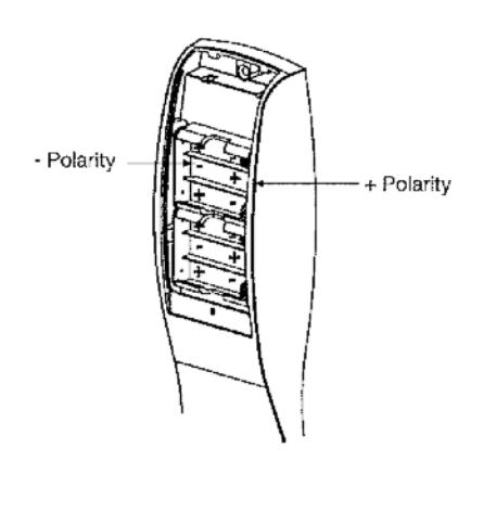
Warning To comply with "Fire Listed" doors, the batteries must be replaced with alkaline batteries only.
2 General Description
IMPORTANT
- The Profile v.G1.5 Series provides enhanced software and hardware features.
- New v.G1.5 controllers replace v.G1 controllers. Product is still ordered as "G1-" prefix. Controllers are labeled "G1.5"
The SARGENT Keypad Cylindrical Lock is designed for areas which require stand alone authorized entry. It is a self-contained microprocessor-controlled keypad with non-volatile memory. The keypad will hold a total of 100(LK)/2000 (G1-LÚ, G1-PK, G1-PA, G1-TÚ, G1-TP, G1-TA) different user codes. Úser codes "01" & "02" are utilized for Master Code and Supervisory Code, respectively.
This product is operated by six (6) "AA" alkaline batteries.
Specifications
- 1/2" standard 3/4" throw fire-rated double doors Latch – (optional) (41- prefix)
- Deadlocking latch
- Outside lever controlled by keypad, or key retracts latch
- Inside lever retracts latch
- Locks furnished for 1-3/4" doors only
- U.L. Listed
Features
- Non volatile memory
- Motor driven, battery operated
- Battery operated with 6 "AA" Alkaline
- Low battery alert-4 chirps after code entry
- External remote "request to enter"
- Master, Emergency or Supervisory code will unlock door when low battery has expired
- 100 (LK) or 2000 (G1-LU, G1-PK, G1-PA, G1-TU, G1-TP, G1-TA) users
- Programming done at keypad or with a PDA using SofLink™ Plus software and a PC (G1-TA & G1-TP require software)
- RF Fob and Proximity Card, Tag, Fob are optional
- Operates utilizing any two to six digits per code. Digits may be repeated and codes may start with zero
- Cvlinder override
- Entry of three wrong User Codes disables all codes for ten seconds. Yellow LED on solid
- · Piezo horn can be heard with each keystroke or turned off by Master or Supervisory Code
- Last 15 transactions can be output to portable print via infrared link (LK Only)
- Last 2000 (Except LK) transactions can be output to PC via SofLink™ Plus Software
Profile Series v.G1.5 Cylindrical Lock
SARGENT ASSA ABLOY
5 Parts Breakdown (Continued)
| ITEM | PART No. | DESCRIPTION | REQ'D |
|---|---|---|---|
| 1 | 10-2000 | 2-3/4" Backset Latch (Standard) | 1 |
| 10-2053 | 3-3/4" Backset Latch (23 Prefix) | 1 | |
|
10-2058
10-2634 |
5" Backset Latch (25 Prefix) 3/4" Throw (41 Prefix) | 1 | |
| 2 | 10-3026 | Outside Escutcheon Key Pad, Key Pad/Prox (LK) | 1 |
| 2 | 10-3130 | Outside Escutcheon Key Pad, Key Pad/Prox (G1-LU, G1-PK, G1-TU, G1-TP) | i |
| 10-3131 | Outside Escutcheon Prox Only (G1-PA, G1-TA) | i | |
| 10-3016 | Outside Escutcheon Housing Only | i | |
| 52-2432 | Keypad/Proximity Bezel Assembly w/ Harness (LK) | 1 | |
| 52-2704 | Key Pad/Proximity Bezel Assembly w/ Harness (G1-LU, G1-PK, G1-TU, G1-TP) | 1 | |
| 52-2706 | Prox Only Bezel Assembly w/ Harness/(G1-PA, G1-TA) | 1 | |
| 3 | 10-3020 | Inside Escutcheon and 100 User Controller (LK) | 1 |
| 10-3126 | Inside Escutcheon and 2000 User Controller (G1-LU) | 1 | |
| 10-3127 | Inside Escutcheon and Key Pad/Prox or Prox Only Controller (G1-PA, G1-PK) | 1 | |
| 10-3015 | Inside Escutcheon Housing Only | 1 | |
| 52-2439 | 100 User (LK) Key Pad Controller Assembly | 1 | |
| 52-2733 | 2000 User (G1-LU) Key Pad Controller Assembly | 1 | |
| 52-2734 | 2000 User (G1-PA, G1-PK) Prox Only or Prox Key Pad Controller Assy. | 1 | |
| 52-2736 | 2000 User (G1-TA, G1-TP) Prox Only or Prox/Keypad Controller Assembly w/ RF Te | cnnology | |
| 4 |
52-2735
10-0523 |
2000 User (G1-TU) Keypad Controller Assembly w/ RF Technology | 1 |
| 4 | 10-0523 | "B" Inside Lever/Passage | |
| 10-2204 | "J" Inside Lever/Passage NOTE: Coastal Levers & Cylinders other than Standard - See 10 Line Parts "L" Inside Lever/Passage | Pages 1 | |
| 10-0501 | "P" Inside Lever/Passage | 1 | |
| 10-0534 | "B" Inside Lever (75- Handicap Warning) | i | |
| 10-2245 | "J" Inside Lever (75- Handicap Warning) | i | |
| 10-0512 | "L" Inside Lever (75- Handicap Warning) | i | |
| 10-0556 | "P" Inside Lever (75- Handicap Warning) | i | |
| 5 | 52-2437 | Battery Cover Only | 1 |
| 52-2509 | Battery Cover RF Technology (G1-TU, G1-TP, G1-TA) | ||
| 6 | 10-0019 | Cylinder Spacer | 1 |
| 7 | 10-0792 | Spacer Bushing | 2 |
| 9 | 10-3048 | Inside Rose Spring Assembly | 2 |
| 10 | 10-0524 | "B" Outside Lever Standard Cylinder NOTE: Coastal Levers & Cylinders ot | her 1 |
| 10-2205 | "J" Outside Lever Standard Cylinder than Standard See 10 Line Parts Page | ||
| 10-0502 | "L" Outside Lever Standard Cylinder | 1 | |
| 10-0546 | "P" Outside Lever Standard Cylinder | 1 | |
| 10-0525 | "B" Outside Lever (30- To Accept Schlage Cylinder) | ] | |
| 10-2206 | "J" Outside Lever (30- To Accept Schlage Cylinder) | 1 | |
| 10-0503 | "L" Outside Lever (30- To Accept Schlage Cylinder) "B" Outside Lever (20- To Accept Schlage Cylinder) | 1 | |
|
10-0547
10-1535 |
"P" Outside Lever (30- To Accept Schlage Cylinder) "B" Outside Lever Standard Cylinder (76- Handicap Warning) | 1 | |
| 10-1535 | "J" Outside Lever Standard Cylinder (76- Handicap Warning) | 1 | |
| 10-0513 | "L" Outside Lever Standard Cylinder (76- Handicap Warning) | i | |
| 10-0557 | "P" Outside Lever Standard Cylinder (76- Handicap Warning) | i | |
| 11 | 10 0007 | Key (Provided with Cylinder) | |
| 12 | 10-3049 | Outside Rose Spring Assembly | 1 |
| 13 | 13-3266 | Cylinder (Standard) | 1 |
| 13-3613 | Schlage (SC) Cylinder (95-(SC)) | 1 | |
| 13-3614 | Schlage (SE) Cylinder (95-(SE)) | 1 | |
| 10-0019 | Schlage (SC, SÉ & Signature) Cylinder Spacer | 1 | |
| 13-3491 | Cylinder (22-Construction) | 1 | |
| 13-3713 | Cylinder (10-Signature) | 1 | |
| 13-3871 | Cylinder (10-21 Signature Construction) | 1 | |
| 13-3944 | Cylinder (21-Cylinder) | 1 | |
| 18-4020 | Cylinder (VA-ASSA V10) | 1 | |
| 18-4063 | Cylinder (VS-ASSA V10) | 1 | |
| 14 | 01-9170 | Screws for Through Bolts (#10-32 x 1-3/4") | |
| 15 | 10-0312 | Cylinder Retainer - All Cylinders except Removable and Interchangeable core | 1 |
| - 10 | 10-0313 | Cylinder Retainer - Removable Core or Interchangeable Core | |
| 16 | 10-2642 | 77 Lock Body (Std, 10, 21, 23, 30, SC, SE, VA & VS Prefixes only) | 1 |
| 10-2643 | 77 Lockbody (60, 63, 64 Prefixes only) | 1 | |
| 17 | 10-2644 | 77 Lockbody (70, 72, 65-73, 65-73P Lockbody) | 1 |
| 17 | 08-0312 | #800 Strike | 1 |
| 10 | 08-0066 | #808 Strike (28-Prefix) | l |
| 18 |
52-0033
45 1340 |
Fire Stop Plate and Screws (2) | 1 |
| 19 |
45-1340
52 2200 |
Flat Head Screw (Security) Screw Pack (includes item #'s 18, 19, 24, 25) | 1 |
| 20 |
52-2300
01-0297 |
1/8" Security Socket Allen Wrench (item 24) | 1 |
| 21 | 10-2052 | Screw Pack – Specify Finish (Strike Screws, Latch Screws, Push Pin Tool, Strike Bo | x) 1 |
| 23 | 52-0253 | Battery Keeper | 1 |
| 52-0344 | Battery Keeper – RF Technology (G1-TU, G1-TP, G1-TA) | • | |
| 24 | J= UJ 1 1 | See Item # 20 Screw Pack | |
| 25 | See Item # 20 Screw Pack |
6.1–Verify Hand and Bevel of Door
Stand on outside/locked side of the door when determining the door hand
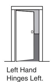
Open inward.
"LH"
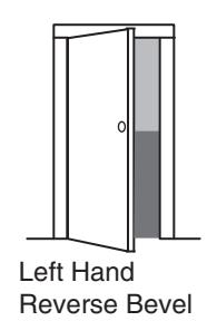
Hinges Left. Open Outward "LHRB"
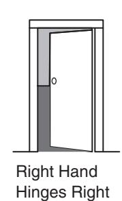
Open Inward.
"RH"
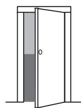
Right Hand Reverse Bevel Hinges Right. Open Outward. "RHRB"
6.2–Door Preparation
Prepare door according to appropriate template (see website www.sargentlock.com):
- For metal door template, see 4531 and 4532
- Wood Door Templates A7456 & A6719 are shipped with product
- Prior to installation, all holes must be free of burrs, debris and sharp edges
- If doors are not properly reinforced per ANSI 115.2, commercially available reinforcements should be installed
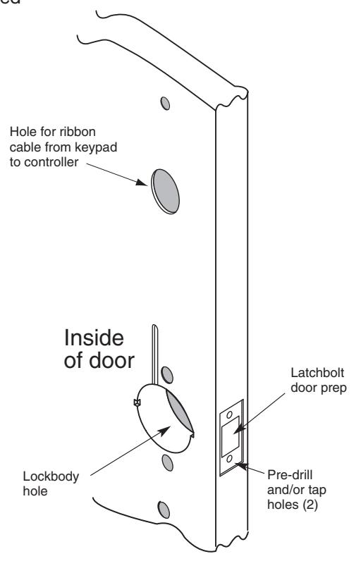
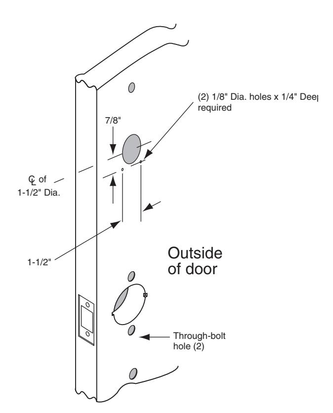
Wood Door Preparation
05/06/09 A7854:B Copyright © 2009, Sargent Manufacturing Company, an ASSA ABLOY Group company. All rights reserved. Reproduction in whole or in part without the express written permission of SARGENT Manufacturing is prohibited.
Profile Series v.G1.5 Cylindrical Lock
6.3–Frame Preparation for Strike
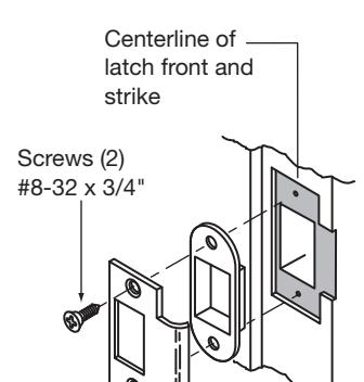
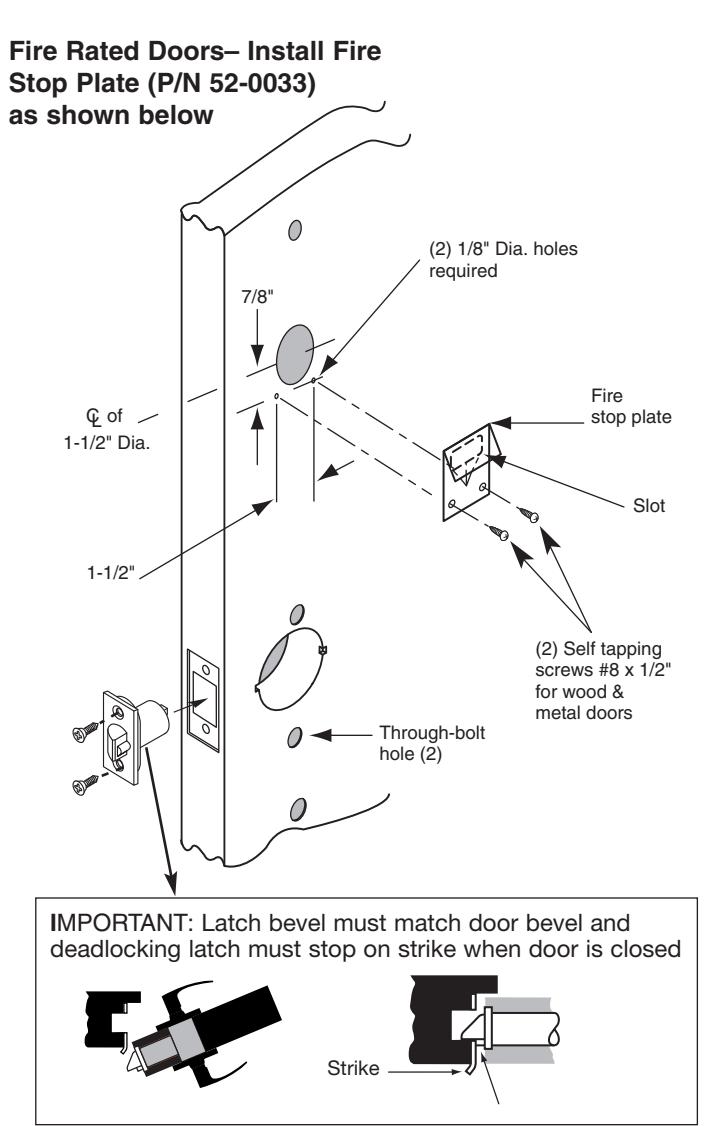
6.4–Latchbolt and Fire Stop Plate Installation
- 1. Install latch with beveled bolt facing the strike.
- 2. Attach with two screws but DO NOT tighten completely at this time.
- 3. Attach Fire Stop Plate with two screws.
Note: Required for all Fire Rated doors
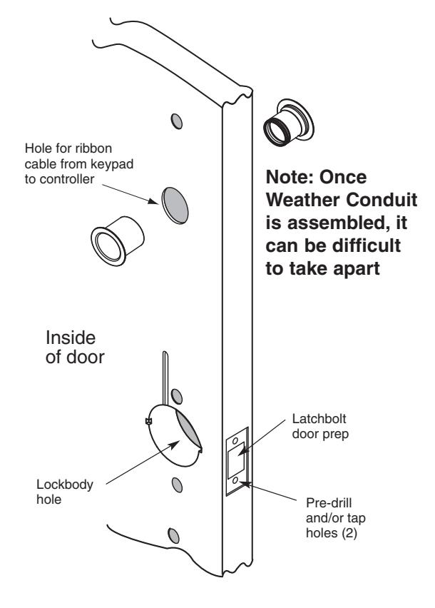
Non Fire Rated Exterior Doors– Install Weather Conduit (P/N 52-2847) as shown below
6.5–Lock Installation
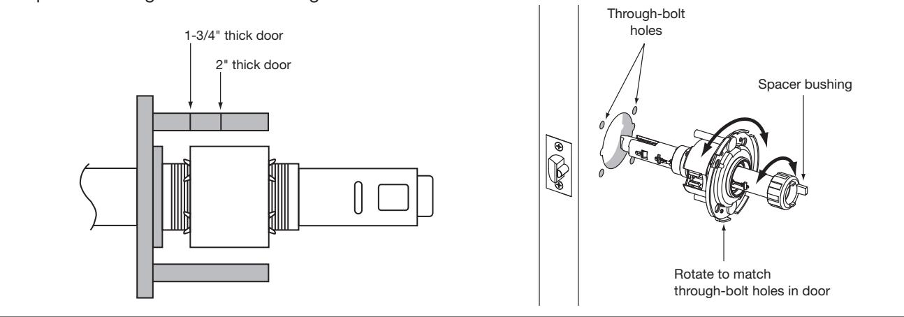
Lock Preset to:
- Through-bolt location– 12 & 6 o'clock
- Door thickness– 1-3/4" thick- see below for other door conditions
Adjustment for different through-bolt and door thickness:
- Through-bolt location– rotate outside rose to match door
- Door thickness– rotate outside rose to align door thickness marking with lockbody edge
- Spacer bushing– remove and realign to fit into back of lever
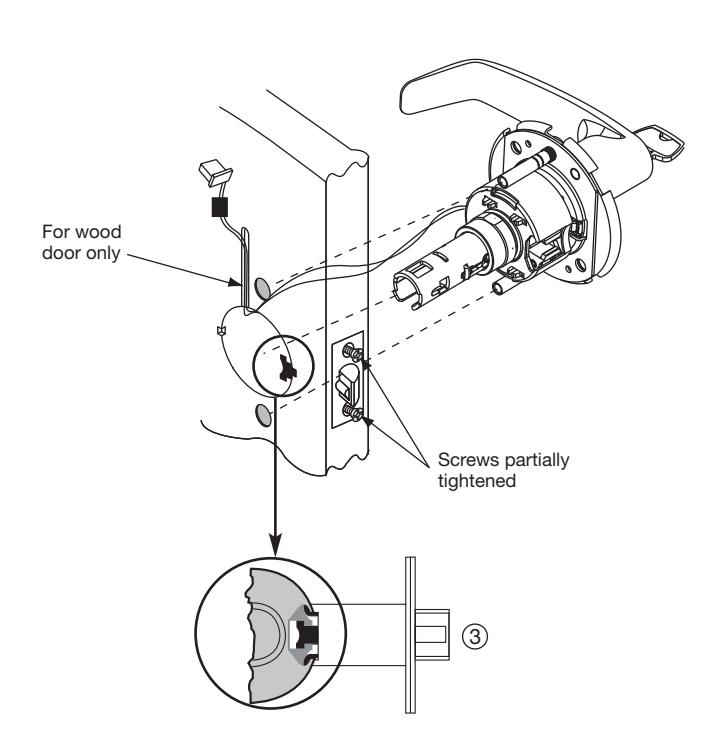
- 1. Feed wires into the lock body hole, from outside of door.
- 2. Lock body into cross-bore hole from outside of the door (locked side).
- 3. Lock body must engage both the latch unit prongs and tail piece, as shown.
IMPORTANT:
Door must remain open during installation. Use door stop.
IMPORTANT Lockbody must be centered in the door
6.6–Securing the Lock in the Door
- 1A. If wood door, feed wires up through the routed channel as shown.
- 1B. If metal door, feed wire and connector through inside of door and out hole on outside of door. *
- 2. Attach inside rose assembly and spacer bushing and secure with screws shown
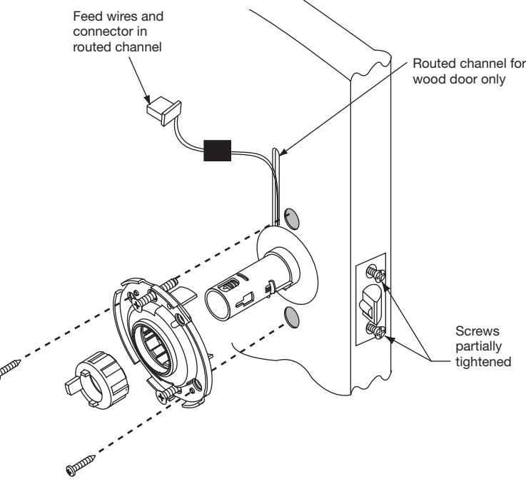
6.7–Remove Outside Lever Only
- 1. Insert key, rotate 45° clockwise and hold
- 2. Depress lever retainer with push pin tool (provided).
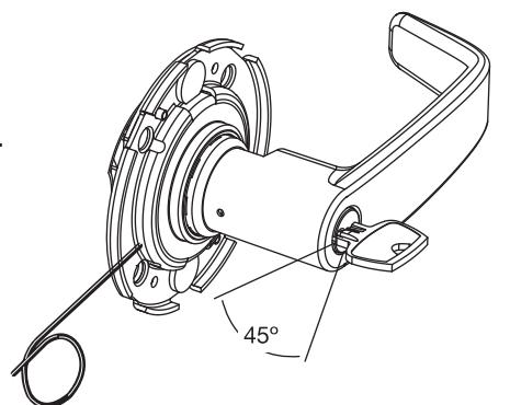
How to Change Cylinder (if required)
- 1. With outside lever in hand, use standard pliers to pull out cylinder retainer.
- 2. Remove key and cylinder from lever.
- 3. Insert new cylinder.
- 4. Secure by pressing cylinder retainer flush with the lever.
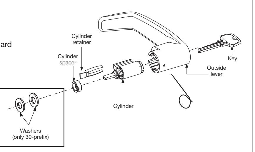
6.8–Installation of Outside Escutcheon and Lever
NOTE: For exterior applications, use weather seal gasket part # (10-0649) between escutcheon and outside door surface
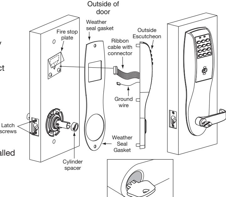
- 1A. For <u>fire rated doors</u> only, feed ribbon cable connector and ground wire from outside of door through weather seal gasket (if used) then fire stop plate.
- 1B. For <u>non-fire rated doors</u> only, feed ribbon cable connector and ground wire from outside of door through weather seal gasket (if used), then conduit sleeve in door (not shown).
- 2. Slide the outside escutcheon over the lock and hold the escutcheon to the door surface.
- 3. Prior to installing outside lever, verify cylinder spacer is inserted into horizontal slot of lock body tube.
- 4. Slide the outside lever onto tube with key horizontal (toward latch). Rotate key 45 degrees clockwise.
- 5. Push lever until lever catch is engaged.
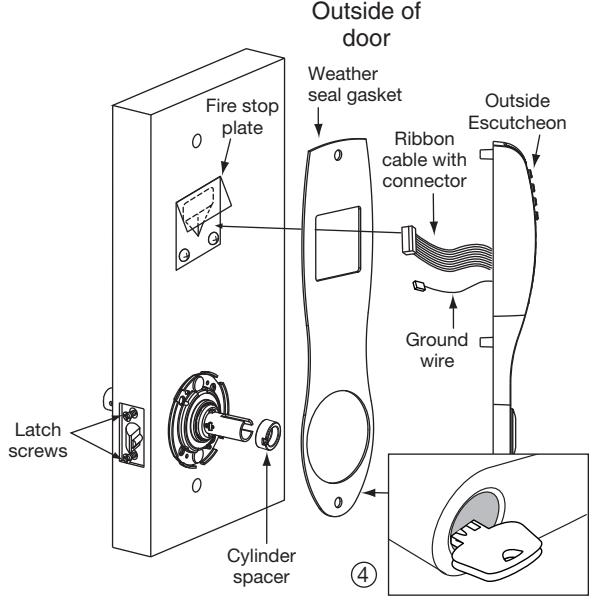
6.9-Inside Escutcheon and Lever
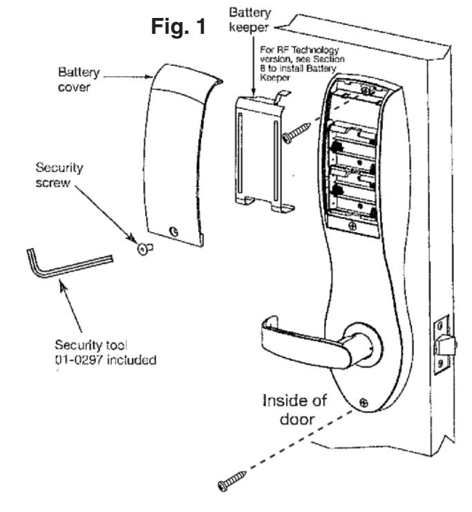
- 1. Remove black battery cover from the escutcheon with security wrench (provided).
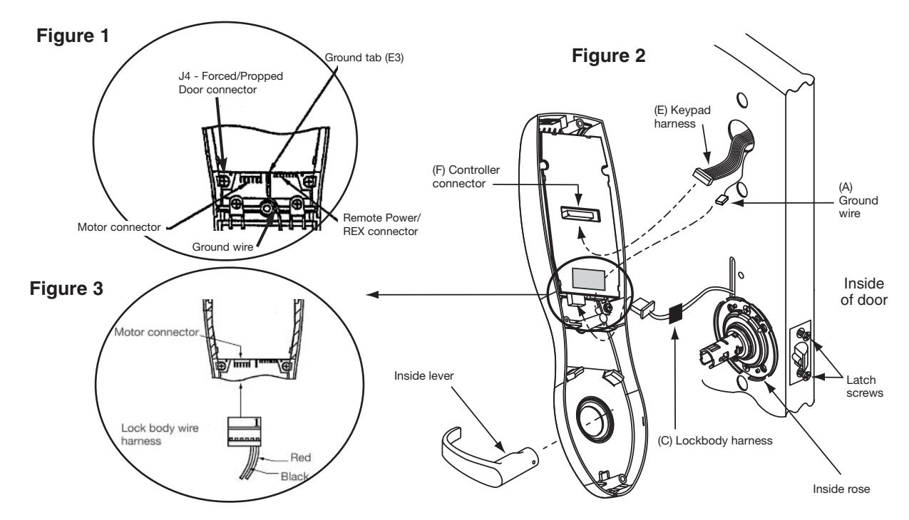
- Connect ground wire to terminal E3 (Fig. 1), connect keypad harness (Fig. 2) to controller, and connect lockbody motor harness (Fig. 3) to motor connector.
- Feed all excess wire through inside door hole and into outside escutcheon cavity, being careful not to pinch wires.
- 4. Tighten two latch screws completely.
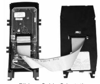
Ribbon Cable Orientation: Install with cable exiting DOWN, as shown.

6.10–Hardwiring Options
Note: If hardwiring IS NOT REQUIRED, go to Mounting of Outside Escutcheon and Battery Installation (6.11)
Hardwiring options include one or a combination of the following; Forced/Propped Door, Hard Power and/or Remote Unlock (REX)
6.10.A–Important
- 1. Caution: Disconnect all input power before beginning installation to prevent electrical shock and equipment damage.
- 2. Installer must be a trained, experienced service person.
- 3. All wiring must comply with applicable local electrical codes, ordinances and regulations.
6.10.B–Installation Notes
- 1. With new applications, an ElectroLynx® door harness with 8 and 4 pin connectors will be pre-installed inside door by Assa Abloy door manufacturer when specified during ordering process.
- 2. Wiring to pigtail harness is per facility wiring requirement. ElectroLynx® connector terminations and wire colors all match.
- 3. If door does not have an ElectroLynx® type door harness, cut connectors off product and hardwire, or consult factory for appropriate mating harness.
6.10.C–ElectroLynx® Connector System Notes:
The system is designed to be installation friendly with pluggable connectors from the electric hinge through the door to the rail. The only wiring required is to the loose wires on the pigtail harness assembly on the frame side of the electric hinge.
IMPORTANT:
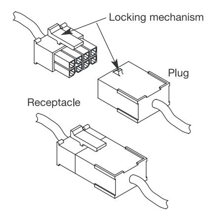
The plug and receptacle connectors are designed to mate and lock together as shown in the figure. Plug the connectors into each other with the locking mechanism aligned as indicated.
Do NOT force connectors on any other way.

ElectroLynx®
As part of their promise to provide innovative, fast and effective, and higher security solutions to their customers, ASSA ABLOY Group companies offer ElectroLynx, a universal quick-connect system that simplifies the electrification of the door opening.
ElectroLynx® is a registered trademark of ASSA ABLOY, Inc.
Installation
-
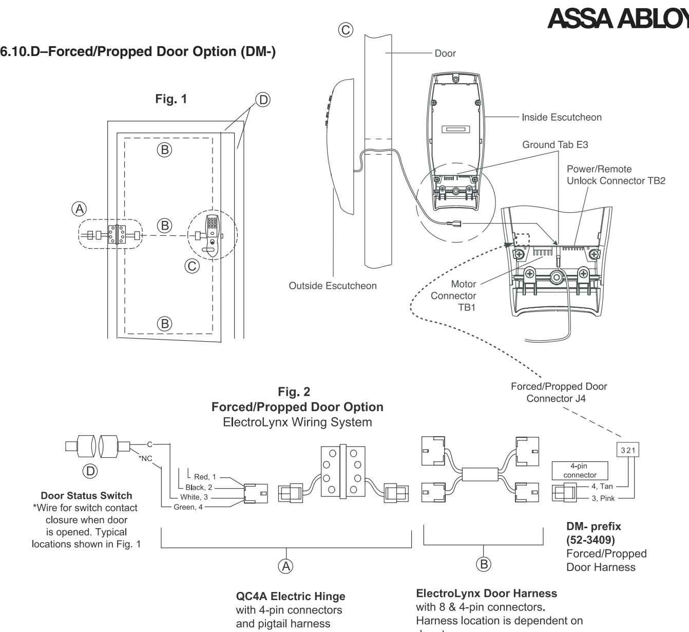
1. ElectroLynx® System Wiring Instructions (refer to Fig. 1 and Fig. 2)
- a. Look for the mating part on ASSA ABLOY doors & frames. Then plug in all connectors as shown in Fig. 2 during product installation
- b.Hard wire door status switch as shown
-
2. Non-ElectroLynx® System Wiring Instructions (refer to Fig. 1 and Fig. 2)
- a. Cut the 4-pin connector off the Forced/Propped harness and hard wire to non-ElectroLynx® two conductor door harness.
- b. Hard wire door harness to power transfer device
- c. Hard wire door status switch to power transfer device
Profile Series v.G1.5 Cylindrical Lock
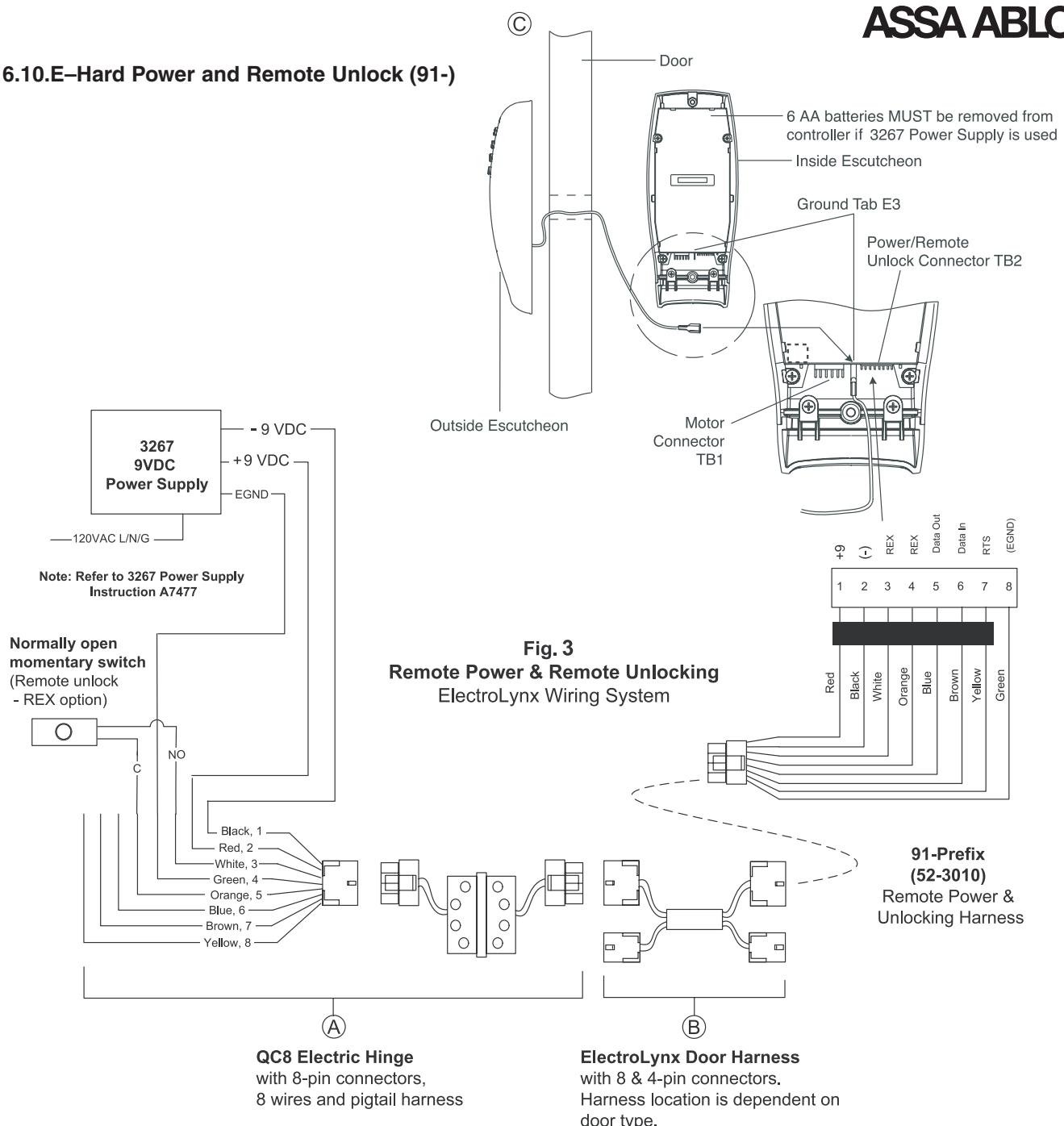
Installation
-
1. ElectroLynx® System Wiring Instructions (refer to Fig. 1 and Fig.3)
- a. Look for the mating part on ASSA ABLOY doors & frames. Then plug in all connectors as shown in Fig. 3 during product installation
- b. Hard wire hard power and/or remote unlock (REX), as shown
-
2. Non-ElectroLynx® System Wiring Instructions (refer to Fig. 1 and Fig.3)
- a. Cut the 8-pin connector off the Remote Power/Unlock harness and hard wire to non-ElectroLynx® door harness. Remote power requires three conductors and remote unlock requires two conductors.
- b. Hard wire door harness to power transfer device
- c. Hard wire hard power and/or remote unlock (REX), as shown
Profile Series v.G1.5 Cylindrical Lock
6.10.F–Hard Power and Remote Unlock (91-) with Forced/Propped Door (DM-)

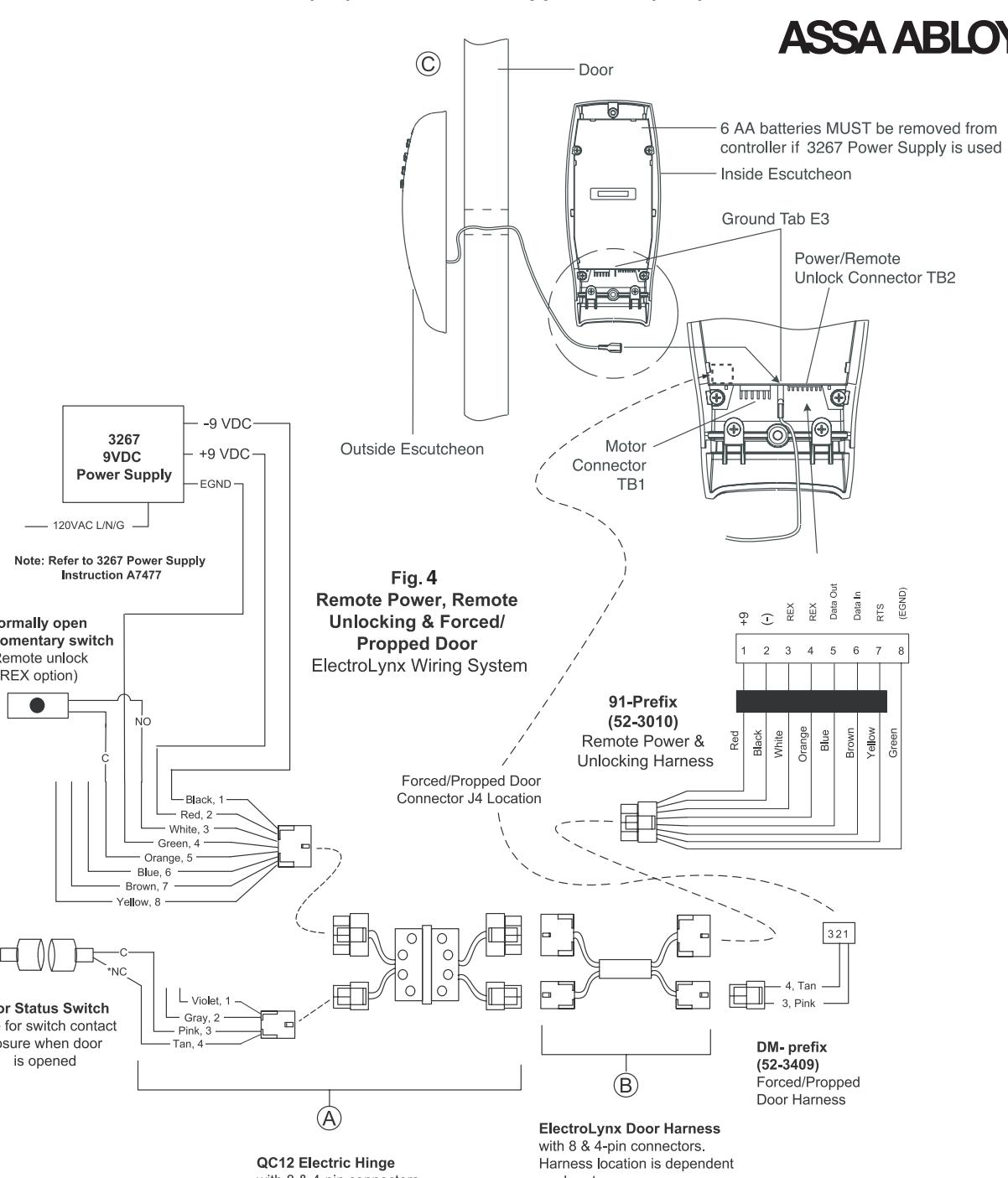
Installation
-
1. ElectroLynx® System Wiring Instructions (refer to Fig. 1 and Fig. 4)
- a. Look for the mating part on ASSA ABLOY doors & frames. Then plug in all connectors as shown in Fig. 4 during product installation
- b. Hard wire forced/propped, hard power and/or remote unlock (REX), as shown
-
2. Non-ElectroLynx® System Wiring Instructions (refer to Fig. 1 and Fig. 4map)
- a. Cut the 8-pin connector off the Remote Power/Unlock harness and hard wire to non-ElectroLynx® door harness. Remote power requires three conductors and remote unlock requires two conductors.
- b. Hard wire door harness to power transfer device
- c. Hard wire forced/propped, hard power and/or remote unlock (REX), as shown
6.11–Mounting of Outside Escutcheon and Battery Installation
NOTE: Connectors go on only one way. Do not offset connector and be sure they are completely sealed.
1. Insert two #8-32 screws (Fig. 2) through top and bottom of inside escutcheon and thread into outside escutcheon. Straighten escutcheons and tighten securely, being careful to avoid pinching wires.
NOTE: For RF Technology versions (G1-TU, G1-TP, G1-TA), refer to Section 8 to install through-bolt screws.
2. Slide the Inside Lever onto the tube.
7 Operational Check
For devices with cylinders:
- 1. Insert key into cylinder and rotate.
- 2. The key will retract the latch. Key should rotate freely
- 3. Inside lever retracts latch and deadbolt (if provided)
- 4. Enter 1234* to unlock outside lever handle and retract latch and deadbolt (if provided)
- 5. If lock is prox only (G1-PA) or RF Technology with Prox (G1-TA) refer to Keypad programming instruction manual

The RF Technology Lock (G1-TU, G1-TA, G1-TP) is installed as described in section 6 with the following exceptions:
- Installation of the top through-bolt screw
- Removal process for the battery keeper
8.1-Installation of the top through-bolt screw
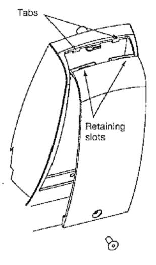
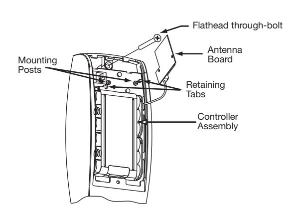
The antenna board must be carefully moved to access the upper through-bolt screw. Care should be taken to prevent damage to the antenna retaining tabs during this process.
Press the two tabs away from the antenna board and lift the board off the mounting posts. Insert the flat head throughbolt and secure the escutcheon in place. After tightening the top through-bolt, replace the antenna board by placing it on the mounting posts and pressing into the retaining tabs.
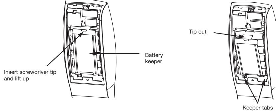
8.2-Removal procedure for the Battery Keeper
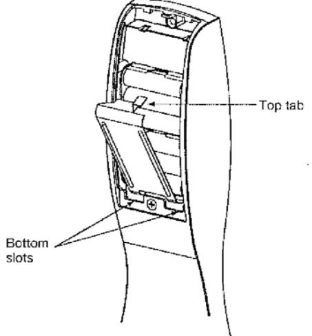
To remove the battery keeper, a flat bladed screwdriver or similar tool must be used.
Insert the screwdriver into the slot at the top of the battery keeper, lift up and pull the top of the keeper away from the batteries.
To install, insert the tabs on the bottom of the keeper into the battery compartment slots and press the keeper tightly against batteries.
05/06/09 A7854:B

SARGENT Manufacturing Company 100 Sargent Drive New Haven, CT 06511 USA 800-727-5477 • www.sargentlock.com
Founded in the early 1800s, SARGENT® is a market leader in locksets, cylinders, door closers, exit devices, electro-mechanical products and access control systems for new construction, renovation, and replacement applications. The company's customer base includes commercial construction, institutional, and industrial markets.
Copyright © 2009 Sargent Manufacturing Company, an ASSA ABLOY Group company. All rights reserved. Reproduction in whole or in part without the express written permission of Sargent Manufacturing Company is prohibited.