Pemko Henderson Industrial Stainless Steel Catalog
Open the original PDF document
View PDF
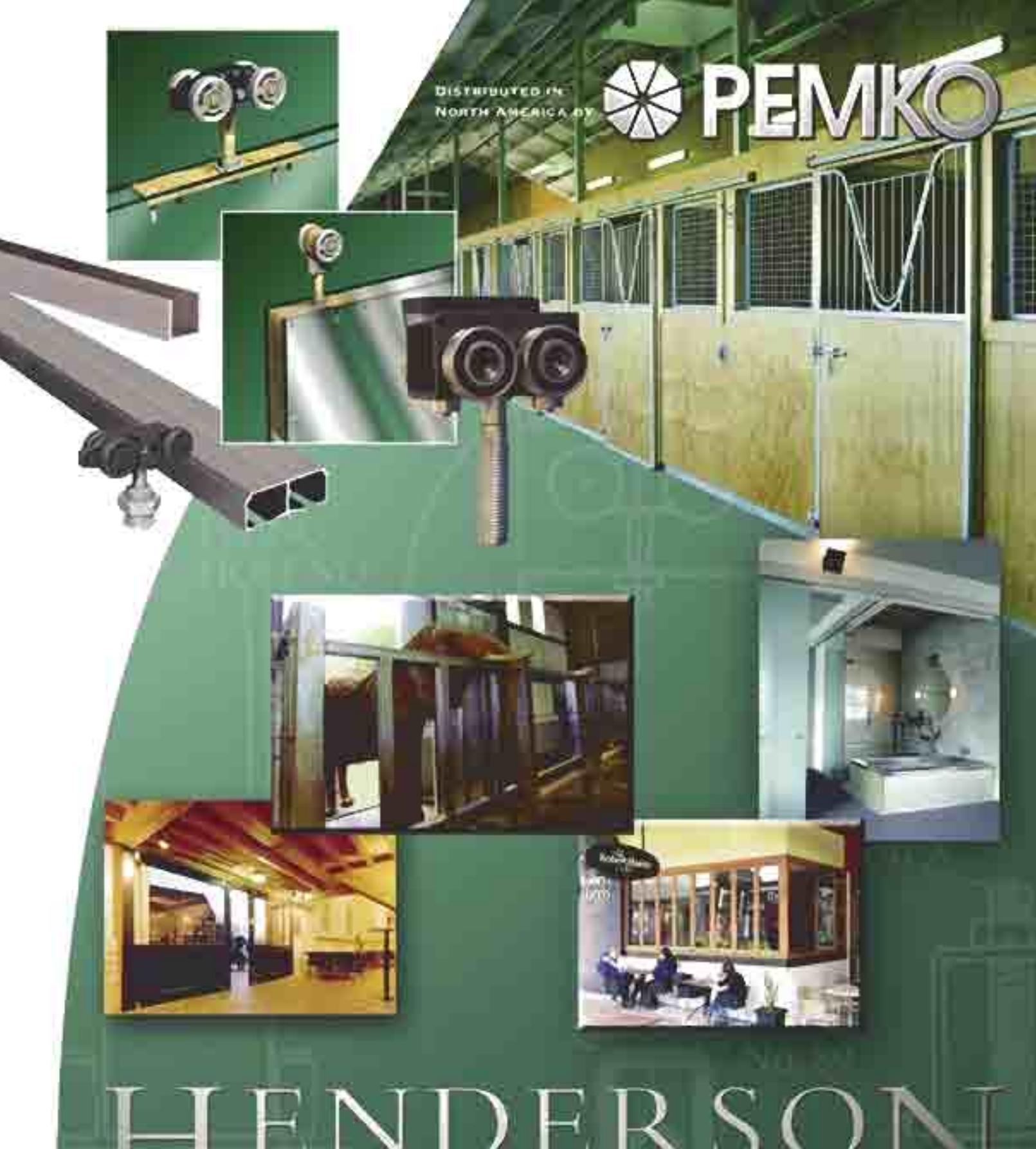
COMMERCIAL AND INDUSTRIAL SLIDING AND FOLDING DOOR HARDWARE

Contents
| Introduction to |
|---|
| PC Henderson |
Pg 2
Commercial Straight Sliding Systems
Pg 3
| Husky | → | 100 and 200 lbs. | Pg 4 | |
|---|---|---|---|---|
| Husky | - |
Glass Panels
up to 165 lbs. |
Pg 6 | |
| Pacer | → | Wood and Metal Doors up to 440 lbs. | Pg 7 | |
| Pacer | → | Glass up to 285 lbs. | Pg 9 | |
| = | Florinal | - | Wood, Metal, or Glass | Pa 12 |
Commercial Folding Systems
Pg 14
| 0 / | U | ||
|---|---|---|---|
| Husky → | ➤ 55 and 100 lbs. | Pg 16 | |
| Pacer Centerfold | ➤ Wood Doors up to 165 lbs. | Pg 18 | |
| Pacer Endfold → | ➤ Wood Doors up to 165 lbs. | Pg 20 | |
| Pacer Endfold - | Glass Doors up to 99 lbs. | Pg 22 | |
| Pacer Endfold Exter | rior | Pg 24 | |
| Pacer Endfold Alum | inum | Pg 26 | |
| Flexirol Centerfold | Pg 28 | ||
| Flexirol Endfold Inte | erior | Pg 30 | |
| Flexirol Endfold Ext | erior | Pg 32 | |
| Flexirol Endfold Alu | minum | Pg 34 | |
| Flexirol Folding Gla | ss | Pg 36 | |
Commercial Multidirectional Systems Pg 38
| Pacer 135° |
→ Wood and Aluminum
Doors up to 264 lbs. |
Pg 40 |
| Pacer 135° | → Glass Doors up to 264 lbs. | Pg 42 |
| Flexirol 90° |
→ Wood and Aluminum
Doors up to 220 lbs. |
Pg 44 |
| Flexirol 90° | → Glass Doors up to 220 lbs. | Pg 46 |
| Flexirol 135° |
Wood and Aluminum
Doors up to 1100 lbs. |
Pg 48 |
| Flexirol 135° | → Glass Doors\nup to 1100 lbs. | Pg 50 |
Industrial and Stainless Steel Track and Hardware Pg 53
|
Straight Sliding
Industrial |
→ 290-307 wood
Door Hardware |
Pg 54 |
|
Straight Sliding
Industrial |
→ 290-307 metal
Door Hardware |
Pg 56 |
|
Straight Sliding
Commercial (Bottom Roller) |
→ Mansion and Majestic
Wood Door Hardware |
Pg 62 |
|
Straight Sliding
Industrial (Bottom Roller) |
→ Sherwood 225-800
Wood Door Hardware |
Pg 66 |
|
Straight Sliding
Industrial (Bottom Roller) |
→ Sherwood 225-800
Metal Door Hardware |
Pg 70 |
|
Folding
Industrial |
→ Tangent 290-305
Folding Door Hardware |
Pg 74 |
|
Round-the-
Corner Industrial |
→ Tangent 290-305
Round-The-Corner Door Hardware |
Pg 78 |
|
Folding
Partitions |
→ Council 290-305 End
Folding Door Hardware |
Pg 82 |
|
Folding
Partitions |
→ Council 290-305 Center Folding Door Hardware | Pg 86 |
|
Folding Section
Doors (Bottom Roller) |
→ Arcade A70
End Folding and Center Folding Door Hardware |
Pg 90 |
|
Overhead
Runways |
→ 280-305 | Pg 94 |
|
Sliding
Cantilever Gate Hardware |
→ Titan | Pg 98 |
| inlace Cecal | C4::-a: -la.4 |
Stainless Steel Straight Sliding Industrial Pg 100
|
Track, Guide
Channel, Guides |
→ 28 | 80/SS, 290/SS, 301/SS | Pg | 101 |
| Brackets | → 1/ | SS, 1X/SS, 3/SS, 3X/SS | Pg | 102 |
| Hangers |
84/SS, 285/SS, 53/SS,
6/SS, 57/SS |
Pg | 104 | |
|
Top-Hung
(Wood or Metal Straight Sliding) |
→ 28 | 30/SS | Pg | 105 |
|
Top-Hung
(Wood or Metal Straight Sliding) |
→ 29 | 90/SS | Pg | 106 |
|
Top-Hung
(Wood or Metal Straight Sliding) |
→ 30 | 01/SS | Pg | 108 |
Component Illustrations Pg 110
| Components | ~ |
Hinges, Brack
Pivot Sets, Gui |
110 | ||
|---|---|---|---|---|---|
| Track & Channel | ~ |
280-307 Tra
89-99 Char |
Pg | 118 | |
| Track Brackets | ~ | Pacer, Flexi | rol, Husky | Pg | 119 |
| Hangers | Pg | 120 | |||
| Guides and Other | r Ac | cessories | Pg | 121 | |
| P C Henderson A | dve | ertising | Pg | 122 | |
Product Index
Pg 124
HENDERSON
P C Henderson has long been acknowledged as the world leader in the design and manufacture of Sliding Gear Systems for residential, commercial and industrial applications.
Established in 1921, the company is a member of Cardo Door, the largest Business Area within Cardo AB, a major European engineering products group with an annual turnover in excess of £700 million.
P C Henderson is based in Bowburn in North East England and has subsidiaries in Holland and Ireland. The company has a long established sales and distribution network in over 70 countries, with head office support from Henderson's fully trained technical sales team.
The company is committed to quality and is registered to BS EN ISO 9002: 1994 Quality Systems.
HENDERSON COMMERCIAL RANGE
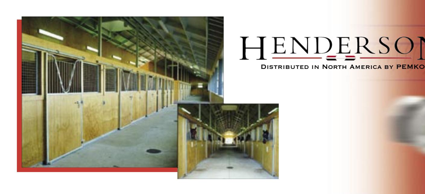
The three models in the Henderson commercial range - Husky Glass, Pacer and Flexirol - are suitable for doors weighing up to 1100 lbs. (500kg). They are ideal for applications such as shop-fronts, hotels, conference centers and offices, where smooth action, high performance and aesthetics are important.
You can choose from wood, aluminum and glass door options, with straight sliding, folding and multidirectional stacking systems. Flexirol multidirectional systems can accommodate 90° and 135° movement. Pacer systems allow 135° movement.
Aluminum track can be painted on site to match interior colors and ceilings. Pacer track has the option of clip-on aluminum fascia.
INDUSTRIAL & STAINLESS STEEL TRACK AND HARDWARE
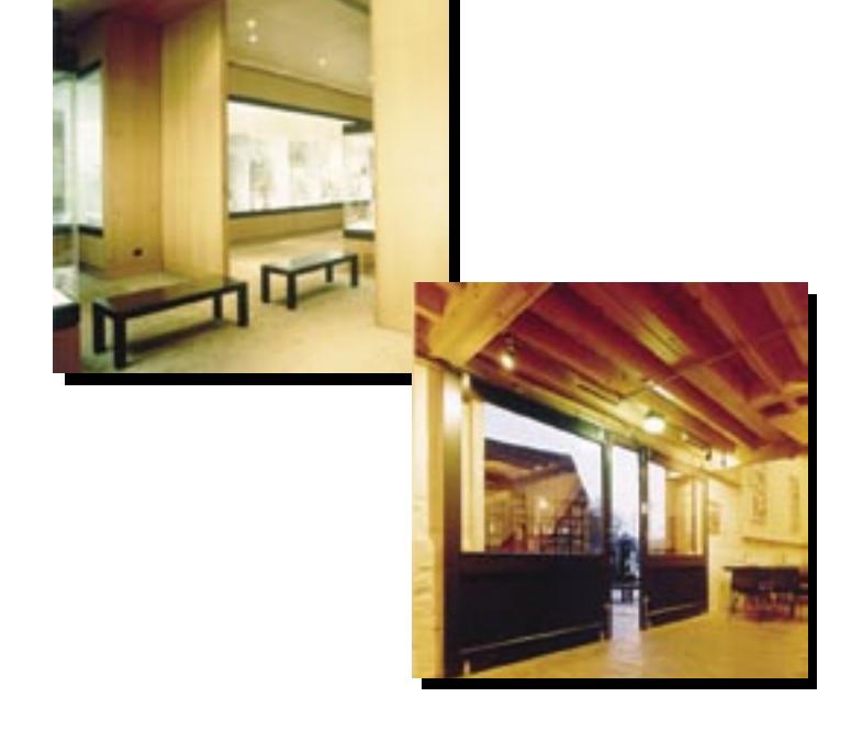
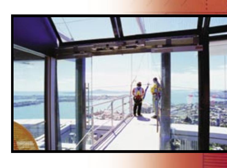
290-307
FOR STRAIGHT SLIDING WOOD DOORS
APPLICATIONS
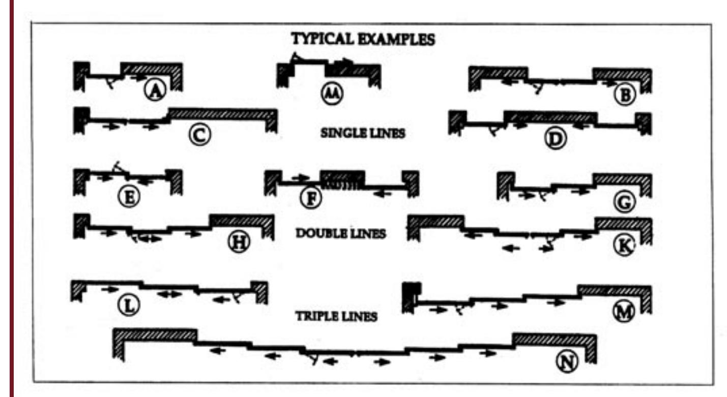
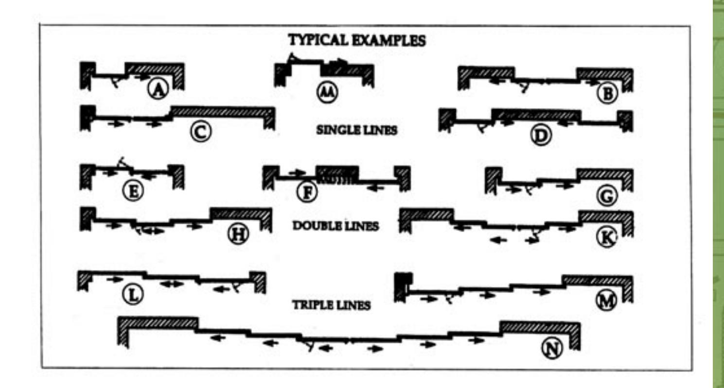
- ◆ The hardware is suitable for industrial and commercial applications, with single or double lines of track, in situations where the structure will support the weight of the door. Where this support is insufficient, "Sherwood" bottom roller hardware should be specified.
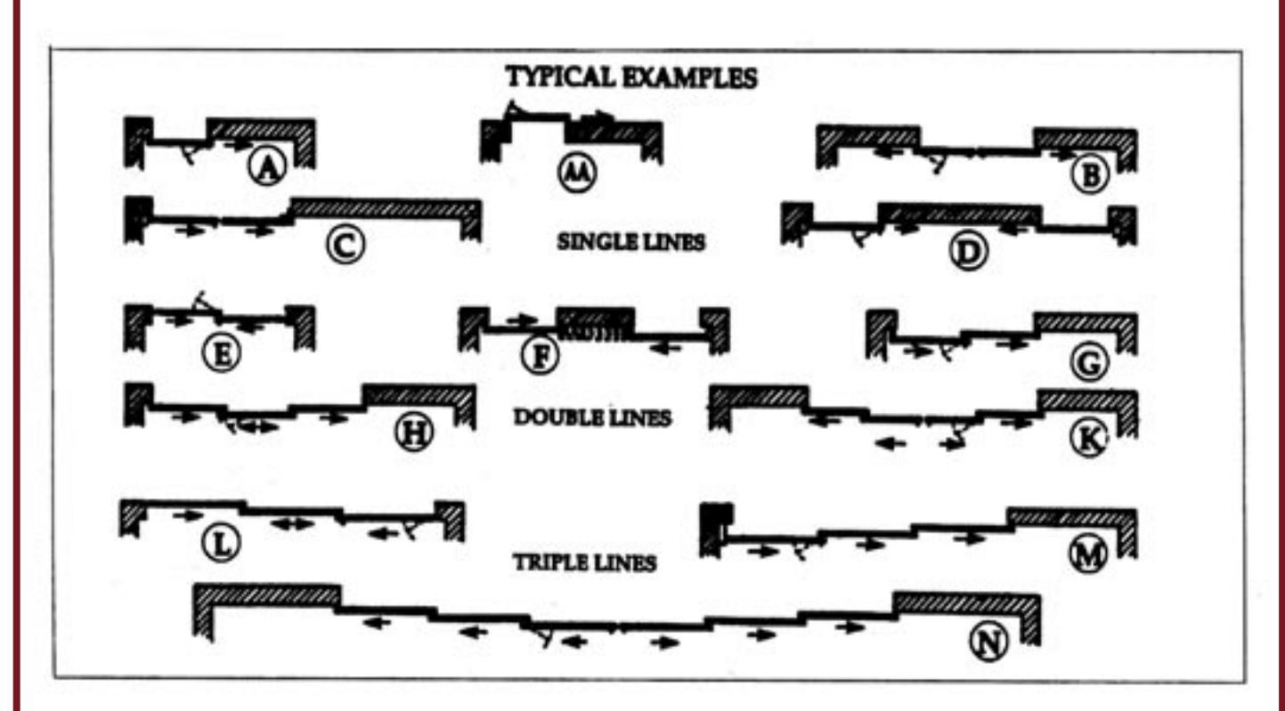
- ◆ Openings may be covered by any number of doors sliding to one or both sides as required. (See plan details).
- On large doors where individual access is required, a wicket door may be incorporated in one of the sliding units.
- Where doors are fitted externally, an overhang is recommended.
For straight sliding wood doors, the following are included:
- Support brackets and track
- ◆ Hangers
- Guides
◆ Full range of
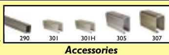
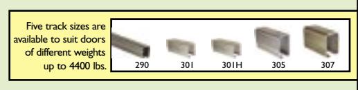
Five track sizes are ailable to suit doors up to 4400 lbs
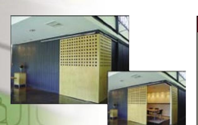
For best operation the door width should not exceed 3/4 of the door height. Wood doors for industrial applications should be framed, ledged and braced.
For commercial applications wood doors may be of flush construction, or fully glazed for showrooms.
Use the table below to estimate the approximate weight (pounds per square foot) of doors of different materials.
| Door Type | lbs./sq. ft. |
|---|---|
| Hollow Metal 18 ga | 4.6 lbs. |
| Hollow Metal 16 ga | 5.8 lbs. |
| Flush Wood, Particleboard Core | 4.8 lbs. |
| Flush Wood, Stave Core | 4.3 lbs. |
| Flush Wood, Mineral Core | 4.7 lbs. |
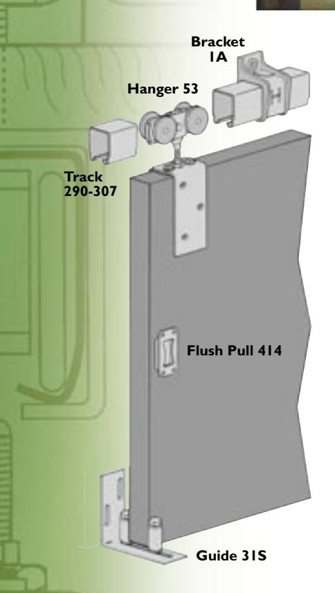
COMPOSITION
Cold-rolled steel section hot-dip galvanized. Track: Brackets: Cast aluminum alloy or pressed steel.
Suitable brackets available for single, double and triple run applications.
Track ends closed by end-clips or closed brackets.
Hangers: Fitted with maintenance-free precision needle bearings, sealed for life.
Adjustable in height.
Steel parts rustproofed by electrozinc plating or painted.
Guides: Choice of bottom guide arrangements available.
For heavier doors, always fit guide channel 97 and guides or 105.
Door Stops
All Dimensions in Feet and Inches
<u>& Accessories</u> : In painted or galvanized steel.
| All Dimensions in Feet and Inches | ||||||
|---|---|---|---|---|---|---|
| Track | 280 | 290 |
301/
301H |
305 | 307 | |
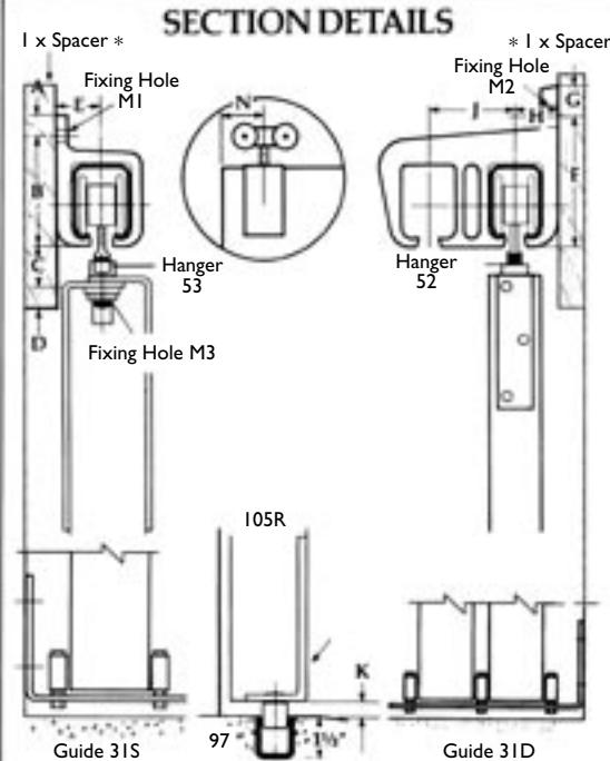
| A | 3/4 | 1/2 | 3/4 | 1 | 1 | |
| В | 1 9 / 16 | 15//8 | 3 13 / 16 | 5 1 / 2 | 61/8 | |
| С | 3/4 | 1 | 2 | 2 | 25/8 | |
| D | 1/2 | 1/2 | 1 | 1 | 11/2 | |
| Е | 5/8 | 1 1 / 16 | 13/8 | 11/2 | 13/4 | |
| F | 3 5 / 32 | 4 3 / 8 | 6 1 / 8 | 7 9 / 16 | ||
| G | 3/4 | 1 5 / 16 | 11/2 | 1 | ||
| Н | 1 1 / 16 | 11/2 | 17/8 | 13/4 | ||
| J | 2 1 / 8 | 31/8 | 35/8 | 35/8 | ||
| K | 3/8 | 3/8 | 3/8 | 1/2 | 1/2 | |
| M1 | 8G | 5 / 16 | 1/2 | 5 /8 | 5/8 | |
| M2 | 1/2 | 5/8 | 3/4 | 3/4 | ||
| М3 | 7 / 16 | 3/4 | 3/4 | 1 | ||
| N | 11/2 | 2 | 3 | 31/2 | 41/2 | |
*When using 280 or 290 track with doors I-3/8" and thicker for a sidewall condition, a spacer must be used behind the bracket.
Answer the questions below and fax (800-283-4050) or call (800-283-9988) Pemko Customer Service for assistance with choosing your hardware. Or use the chart on the following pages to select appropriate hardware for your job.
| JOB NAME | HI SLIDING THA | QUOTE 0 | ORDER D |
|---|---|---|---|
| L. Type of Track Required or Proposed: ☐ Top Hung | Bottom Roller | ||
| ior (inside building) | |||
| 3. Width of Opening: | |||
| Height of Opening: | |||
| Proposed Number of Doors: | |||
| Door Thickness (1-3/8" min 2-1/4" max.): | 0 | ther: | |
| Door Material: Solid Core Leadlined Glazed | ☐ Metal Frame ☐ Hollowcore | if metal frame or leadlined, give d | cteds under question 16 |
| Door Weight: | 100 100 | 500 | |
| Do Doors Slide within Opening (as in plan "E" or "L"): | if NO, go to question 11 | if YES, go to question 13 | |
|
ing, do Doors Slide: Both Ways | ☐ Left Only ☐ Rigi | nt Only |
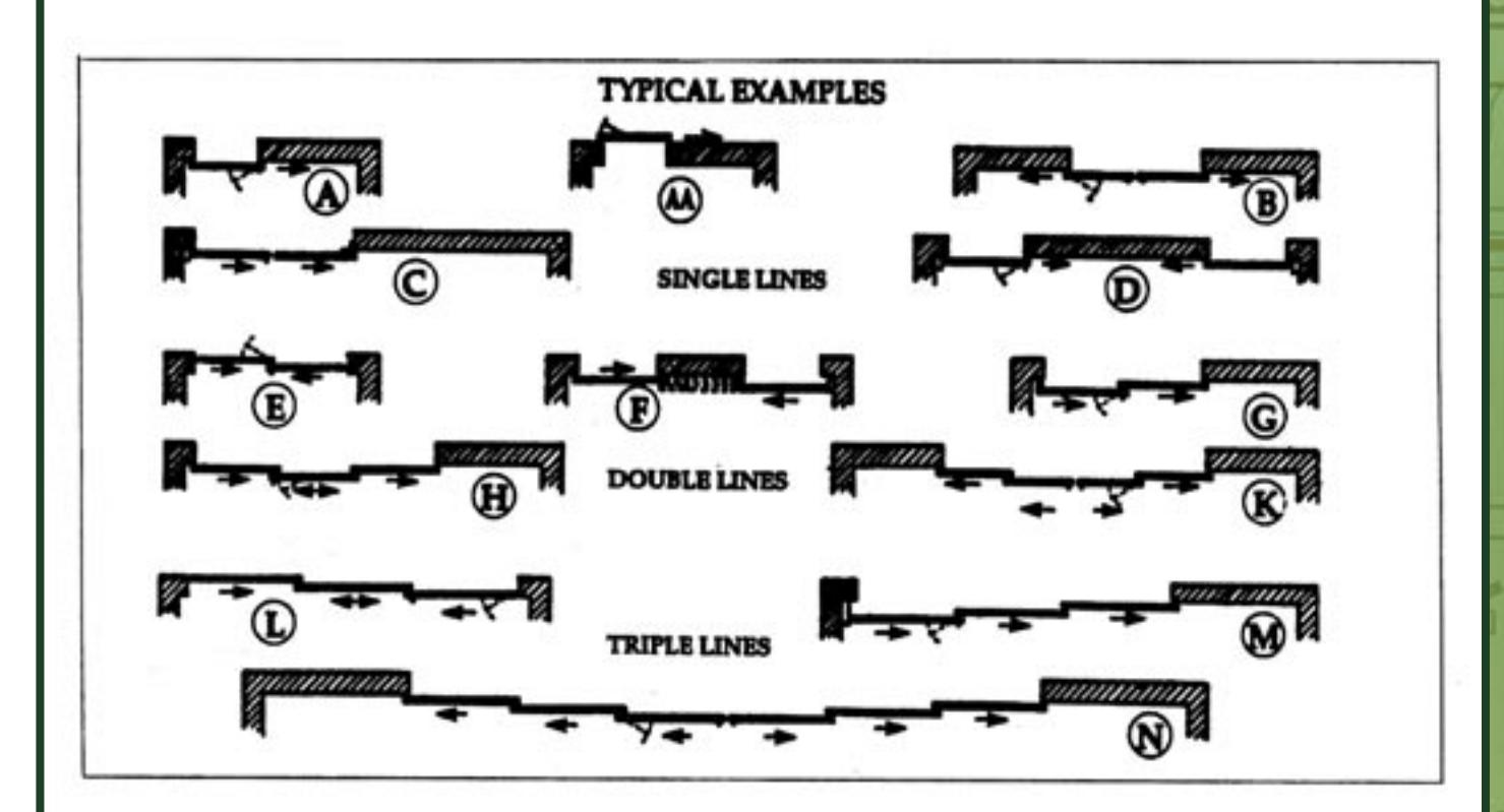
| Do the Doors Slide: [Inside the Building (as in plan "A") | Outside the l | luilding (as in plan "AA") | 201020 |
| How Many Lines of Track? ☐ One ☐ Two | Three | 01440 00 | |
| 3. Bracket Mounting: Sidewall Overhead | |||
| 4. Depth of Header: Width of F | feader: | ||
| 5. Door Construction (metal doors): Angle Frame | Box Frame (depth of section | 0-6") Channel Frame Sp | recial Frame/Leadline |
| 6. Type of Floor: Asphalt Concrete | Steel No Floor (eleva | ted opening) Wood | Tile |
| 7. Type of Wheel Preferred (top hung only - tracks 305 & : | 307 have steel only): Nylon | ☐ Steel | |
| 8. Security: Lock Bolt Unsecured | Will lock bolt be seen from the s | one side of door as doors hung - YES | er NO |
| 9. Number of Identical Openings: |
290-307
HARDWARE KIT FOR STRAIGHT
| 470-301 | TITLE WITH ITT | |||
|---|---|---|---|---|
| Max. Door Height | up to 10 ft. | up to 12 ft. | ||
| 1 | Max. Door Weight | up to 300-400 lbs.* | up to 600-800 lbs.* | |
| Door Thickness | I 1 /2-2" | | 3 /4-2 1 /4" | ||
| 3 | KIT NUMBER | 290 | 301 | |
| Track | 290 | 301 | ||
| Brackets (one bracket for every three feet of track) Jointing Brackets available for joining two pieces of track at bracet (i.e. IAX/301) | IA/290 sidewall-use for Imited installation space 4A/290 overhead-use for Imited installation space 4R/290S overhead-use for ample installation space 4R/290S overhead-use for ample installation space 9A/290 sidewall-use for ample installation space | I A/30 I sidewall-use for overhead-use for limited installation space 4A/30 I 4R/30 IS 9A/30 I sidewall double track limited installation space 4A/30 I overhead-use for overhead-suspended suspended suspended space | ||
| Hangers (two per door) | 52K/N 300 lb. door door top/edge mount 53K/N 300 lb. door* door top mount widoor face flanges 53K/S200 400 lb. door* door top mount widoor face flanges | 53A/S 600 lb. door* door top mount w/door face flanges 600 lb. door door top/edge mount 52A/N 53A/N 800 lb. door* door top/edge mount 57A/S 57A/S 52A/N 800 lb. door* door top/edge mount 57A/N 800 lb. door w/door face flanges door top/edge mount | ||
| Stops (two per door) | 109 HH3/290 double fastener track mounted ground stop double fastener stop | HH3/301 107 single wall mounted stop-double double rubber fastener stop buffers | ||
| Guides (three per door) | 31S 126HD/A heavy duty ground stay roller 106R under guide roller 126 ground stay roller roller guide roller guide roller | 3 I S SI D double wall mounted stay roller roller | ||
| Guide Channel | 94A or 94B 89 steel guide 97 steel guide channel guide channel | 97 steel guide channel | ||
| Flush Pulls | 414 flush pull | 414 flush pull | ||
| Bow Handles | 463 bow handle - 61/4" | 863 bow handle - 51/4" 463 bow handle - 61/4" |
SLIDING WOOD DOORS (complete, ready to install)
| SEIDING WOOD DOOKS (complete, ready to install) | ||||
|---|---|---|---|---|
| up to 14 ft. | up to 16 ft. | up to 20 ft. | ||
| up to 1000 lbs. | up to 1500 lbs. | up to 4400 lbs. | ||
| I 3 /4-2 1 /4" | 1 3 /4-2 1 /4" | 23/8-23/4" | ||
| 301H | 305 | 307 | ||
| 301H | 305 | 307 | ||
| I A/301 sidewall-use for limited installation space 4A/301 overhead-use for ample installation space 4R/301S overhead-use for ample installation space 4R/301S overhead-suspended suspended suspended space 5/301 sidewall double track sidewall-use for ample installation space | 1A/305 sidewall-use for limited installation space 4A/305 overhead-use for limited installation space 4R/305S overhead-use for ample installation space 5/305 sidewall double track limited installation space | 1/307/S sidewall-use for overhead-use for limited installation space space 4/307S overhead-use for ample installation space 4/307S overhead-use for ample installation space 4/307S overhead-use for ample installation space | ||
| 52A/N 1000 lb. door door top/edge mount 53A/N 1000 lb. door 1000 lb. door door top mount door top mount w/door face flanges | 52C/S 1500 lb. door door top/edge mount 53C/S 1500 lb. door door top mount 53C/S 1500 lb. door door top mount w/door face flanges |
53FJ/S
4400 lb. door door top mount w/door face flanges |
||
| HH3/301 track single wall stop-double rubber fastener stop |
107
single wall stop-double rubber buffers |
not required | ||
| 31S 31D double wall mounted stay roller roller | 31S 31D double wall mounted stay roller roller | 31S 31D double wall mounted stay roller | ||
| 97 steel guide channel | 97 steel guide channel 89 steel guide channel | 97 steel guide channel 89 steel guide channel | ||
| 414 flush pull | 414 flush pull | 413 flush pull | ||
| 463 bow handle - 61/4" | 463 bow handle - 6 1 / 4 " | 464 bow handle - 10 1 /4" | ||
290-307
FOR STRAIGHT SLIDING METAL DOORS
APPLICATIONS
- The hardware is suitable for industrial and commercial applications, with single or double lines of track, in situations where the structure will support the weight of the door. Where this support is insufficient, "Sherwood" bottom roller hardware should be specified.
- Openings may be covered by any number of doors sliding to one or both sides as required. (See plan details).
- On large doors where individual access is required, a wicket door may be incorporated in one of the sliding units.
- Where doors are fitted externally, an overhang is recommended.
For straight sliding metal doors, the following are included:
- Support brackets and track
- ◆ Hangers
- ◆ Guides
- Full range of accessories
For best operation the door width should not exceed 3/4 of the door height. Door construction is normally framed and braced using steel angle section then clad with steel sheet or other suitable material. When steel box section is used, specify hangers with extended strap bolts and elongated
guides. If aluminum framed doors are to be used, type of hanger required will depend on door section.
Use the table below to estimate the approximate weight (pounds per square foot) of doors of different materials.
| Door Type | lbs./sq. ft. |
|---|---|
| Hollow Metal 18 ga | 4.6 lbs. |
| Hollow Metal 16 ga | 5.8 lbs. |
| Flush Wood, Particleboard Core | 4.8 lbs. |
| Flush Wood, Stave Core | 4.3 lbs. |
| Flush Wood, Mineral Core | 4.7 lbs. |
COMPOSITION
Track: Cold-rolled steel section hot-dip galvanized.
Brackets: Cast aluminum alloy or pressed steel.
Suitable brackets available for single, double and triple run applications.
Track ends closed by end-clips or closed brackets.
<u>Hangers</u>: Fitted with maintenance-free precision needle bearings, sealed for life.
Adjustable in height.
Steel parts rustproofed by electrozinc plating or painted.
Guides: Choice of bottom guide arrangements available.
For heavier doors, always fit guide channel 97 and guides 104P or 104PX.
*When using 280 or 290 track with doors I-3/8" and thicker for
a sidewall condition, a spacer must be used behind the bracket.
Door Stops
All Dimensions in Feet and Inches
& Accessories: In painted or galvanized steel.
| 7 2 | ||||||
|---|---|---|---|---|---|---|
| Track | 280 | 290 |
301/
301H |
305 | 307 | |
| A | 1/4 | 1/2 | 3/4 | 1 | 1 | |
| В | 1 9 / 16 | 15//8 | 3 13 / 16 | 5 1 / 2 | 6 1 / 8 | |
| С | 3/4 | 1 | 2 | 2 | 25/8 | |
| D | 1/2 | 1/2 | 1 | 1 | 11/2 | |
| Е | 5/8 | 1 1 / 16 | 13//8 | 11/2 | 13/4 | |
| F | 3 5 / 32 | 43/8 | 6 1 / 8 | 7 % 16 | ||
| G | 3/4 | 1 5 / 16 | 11/2 | 1 | ||
| Н | 1 1 / 16 | 11/2 | 17/8 | 13/4 | ||
| J | 2 1 / 8 | 31/8 | 35/8 | 35//8 | ||
| K | 3/8 | 3/8 | 3/8 | 1/2 | 1/2 | |
| M1 | 8G | 5 / 16 | 1/2 | 5/8 | 5/8 | |
| M2 | 1/2 | 5/ 8 | 3/4 | 3/4 | ||
| M3 | 1/8 | 7 / 16 | 11 / 16 | 11 / 16 | 1/8 | |
| M4 | 11 / 16 | 11 / 16 | 11 / 16 | 13 / 16 | 13 / 16 | |
| N | 11/2 | 2 | 3 | 31/2 | 41/2 | |
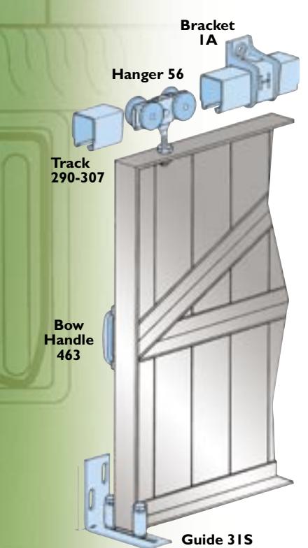
I x Spacer * Fixing Hole M2 Hanger 56 Fixing Hole M3 Fixing Hole M3 Fixing Hole M3 Fixing Hole M4
51/2 51/2
| JOB NAME | HI SLIDING TRA | QUOTE D | ORDER D |
|---|---|---|---|
| Type of Track Required or Proposed: □Top Hung | Sottom Roller | ||
| or (inside building) | |||
| 3. Width of Opening: | ce (made outsting) | ||
| 4. Height of Opening: | |||
| 5. Proposed Number of Doors: | |||
|
0 | ther: | |
| 7. Door Material: Solid Core Leadlined Glazed | ☐ Metal Frame ☐ Hollowcore | if metal frame or lendlined, give de | cteds under question 16 |
| 8. Door Weight: | 10 10 11 | 20 | |
|
if NO, go to question 11 | if YES, go to question 23 | |
| 0. When Looking at the Door from the Inside of the Buildi | ng, do Doors Slide: Both Ways | ☐ Left Only ☐ Righ | nt Only |
| Do the Doors Slide: Inside the Building (as in plan "A") | □ Outside the B | luilding (as in plan "AA") | 107000 |
| 2 How Many Lines of Track? One Two | Three | State 86 | |
| 13. Bracket Mounting: Sidewall Overhead | |||
| 4. Depth of Header: Width of H | leader: | ||
| 5. Door Construction (metal doors): Angle Frame | Box Frame (depth of section) | 0-6") Channel Frame Sp | ecial Frame/Leadlined |
| 16. Type of Floor: ☐ Asphalt ☐ Concrete | Steel No Floor (eleva | ted opening) Wood | Tile |
| 7. Type of Wheel Preferred (top hung only - tracks 305 & 3 | 07 have steel only): Nylon | Steel | |
| 18. Security: Lock Bolt Unsecured | Will lock bolt be seen from the s | one side of door as doors hang - YES o | or NO |
| Number of Identical Openings: |
290-307
HARDWARE KIT FOR STRAIGHT
| 470-307 | ||||
|---|---|---|---|---|
| Max. Door Height | up to 10 ft. | up to 12 ft. | ||
| Max. Door Weight | up to 300-400 lbs.* | up to 600-800 lbs.* | ||
| Door Thickness | I 1 /2-2" | I 3 /4-2 1 /4" | ||
| 3 | KIT NUMBER | 290 | 301 | |
| Track | 290 | 301 | ||
| Brackets (one bracket for every three feet of track) Jointing Brackets available for joining two pieces of track at bracet (i.e. IAX/301) | I A/290 sidewall-use for ample installation space AA/290 AR/290S overhead-use for ample installation space 4R/290S overhead-use for ample installation space 4R/290S overhead-use for ample installation space | I A/30 I sidewall-use for overhead-use for limited installation space 4A/30 I 4R/30 IS overhead-use for ample installation space 4A/30 I sidewall double track 9A/30 I sidewall-use for overhead-use for ample installation space 9A/30 I sidewall-use for ample installation space | ||
| Hangers (two per door) | 56K/S 300 lb. door* door top/ledge mount 56K/S 300 lb. door* door top mount w/door face flanges 57K/N 56K/S200 400 lb. door* door top mount w/door face flanges door top mount w/door face flanges | 56AX/S 600 lb. door* door top mount w/door face flanges 600 lb. door* door top/edge mount 56A/N 800 lb. door* door top mount 800 lb. door* door top/edge mount 56AX/N 800 lb. door* door top mount w/door face flanges 57A/N 800 lb. door* door top/edge mount 56AX/N 800 lb. door* door top/edge mount w/door face flanges 57A/N 800 lb. door* door top mount w/door face flanges | ||
| Stops (two per door) | 109 double fastener single wall or ground stop HH3/290 track mounted double fastener stop | HH3/301 track mounted double fastener stop | ||
| Guides (three per door) | 31S single wall mounted stay roller 106R under guide roller 105 ground stay roller 106 ground stay roller stay roller guide roller | 3 I S S I D double wall mounted stay roller roller | ||
| Guide Channel | 94A or 94B 89 steel guide 97 steel guide channel guide channel | 97 steel guide channel | ||
| Flush Pulls | 414 flush pull | 414 flush pull | ||
| Bow Handles | 463 bow handle - 6 1 / 4 " | 863 bow handle - 51/4" 463 bow handle - 61/4" |
SLIDING METAL DOORS (complete, ready to install)
| up to 14 ft. | up to 16 ft. | up to 20 ft. |
|---|---|---|
| up to 1000 lbs. | up to 1500 lbs. | up to 4400 lbs. |
| I 3 /4-2 1 /4" | I 3 /4-2 1 /4" | 23/8-23/4" |
| 301H | 305 | 307 |
| 301H | 305 | 307 |
| I A/301 sidewall-use for limited installation space AA/301 overhead-use for limited installation space 4A/301 overhead-use for ample installation space Suspended suspended suspended space 5/301 sidewall double track 9A/301 sidewall-luse for ample installation space | IA/305 sidewall-use for limited installation space 4A/305 overhead-use for limited installation space 4R/305S overhead-use for ample installation space | 1/307/S sidewall-use for overhead-use for limited installation space 4A/307 overhead-use for ample installation space 4R/307S overhead-use for ample installation space |
| 57A/N 1000 lb. door door top/edge mount 56AX/N 1000 lb. door door top mount 56AX/N 1000 lb. door door top mount w/door face flanges | 56C/S 1500 lb. door door top/edge mount 56CX/S 1500 lb. door door top mount 56CX/S 1500 lb. door door top mount | 56FJX/S 4400 lb. door door top mount - box frame 56FJ/S 4400 lb. door door top mount w/door face flanges - angle frame |
| HH3/301 107 track single wall mounted stop-double rubber fastener stop buffers |
107
single wall stop-double rubber buffers |
not required |
| 31S 31D single wall double wall mounted stay roller roller | 31S 31D single wall mounted stay roller roller | 31S 31D single wall mounted stay roller roller |
| 97 steel guide channel | 97 steel guide channel 89 steel guide channel | 97 steel guide channel 89 steel guide channel |
| 414 flush pull | 414 flush pull | 413 flush pull |
| 463 bow handle - 6 1 / 4 " | 463 bow handle - 614" | 464 bow handle - 101/4" |
MANSION/ MAJESTIC
FOR STRAIGHT SLIDING WOOD DOORS
For straight sliding wood doors, the following are included:
- ◆ Top guide brackets and top guide, or top guide only
- ◆ Top guide Rollers
- ◆ Bottom Rollers
- ◆ Bottom Rail
- ◆ Full range of accessories
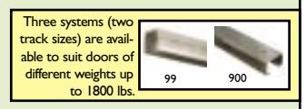
Two track sizes are available to suit doors of different weights up to 600 lbs.
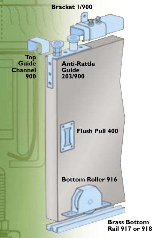
Three systems are available to suit doors of different weights up to 600 lbs. Doors must be constructed with deep bottom rails to accommodate the concealed and
mortised bottom rollers (6" deep for 913XB and 7" deep for 916). Doors may be panelled, flush or glazed.
Use the table below to estimate the approximate weight (pounds per square foot) of doors of different materials.
| Door Type | lbs./sq. ft. | |||
|---|---|---|---|---|
| Hollow Metal 18 ga | 4.6 lbs. | |||
| Hollow Metal 16 ga | 5.8 lbs. | |||
| Flush Wood, Particleboard Core | 4.8 lbs. | |||
| Flush Wood, Stave Core | 4.3 lbs. | |||
| Flush Wood, Mineral Core | 4.7 lbs. | |||
APPLICATIONS
Hardware is designed for straight sliding partitions, picture windows, or fully glazed patio or showroom doors where good class joinery requires the highest quality fittings.
COMPOSITION
<u>Track:</u> Cold-rolled steel section hot-dip galvanized. Aluminum
channel section for lighter doors.
Brackets: Pressed steel, painted finish. Single and double side wall
fixing. Side ear overhead fixing.
<u>Top Guide Rollers</u>: Concealed edge fixing with electrozinc plated aprons and
double adjustable anti-rattle nylon rollers. Concealed edge fixing with electrozinc plated aprons and brass rollers
for light doors.
Bottom Rollers: Steel or aluminum body with brass wheel and ball journal
bearings. Steel electrozinc plated body with nylon wheel
and silver steel axle for light doors.
Bottom Rail: Brass drilled and counter-sunk for wood floor or lugged for
concrete, or brass partly recessed providing weather bar. Aluminum drilled and counter-sunk for light doors.
Flush Pull: In satin anodized aluminum.
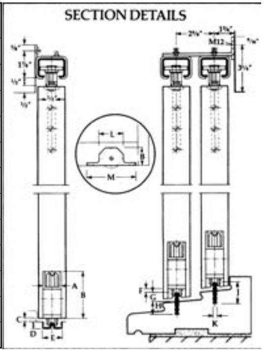
All Dimensions in Feet and Inches
| Track | Mansion | Majestic |
|---|---|---|
| Α | 7/8 | 11/4 |
| В | 17/8 | 31/4 |
| С | 1/4 | 1/4 |
| D | 3/8 | 1/2 |
| Е | 1 | 13/8 |
| F | 1/4 | 1/4 |
| G | 5/8 | 5/8 |
| Н | 5/8 | 7/8 |
| J | 11/4 | 11/2 |
| K | 1/4 | 5 / 16 |
| L | 2 1 / 4 4 5 / 8 | |
| М | 45/8 | 9 |
| JOB NAME | IT SLIDING TR | QUOTE O | ORDER D |
|---|---|---|---|
| 1. Type of Track Required or Proposed: □Top Hung | ☐ Bottom Roller | ||
| 2. Position of Door: ☐ Exterior (exposed) ☐ Interio | or (inside building) | ||
| 3. Width of Opening: | |||
| 4. Height of Opening: | |||
|
|||
|
3 | Other: | |
| 7. Door Material: Solid Core Leadlined Glazed | ☐ Metal Frame ☐ Hollowco | ore if metal frome or lendlined. | give details under question 16 |
| 8. Door Weight: | 100 100 | 77 525 | |
|
if NO, go to question 11 | #YES, go to question 23 | |
| O. When Looking at the Door from the Inside of the Buildin | ng, do Doors Slide: Both Way | n ☐ Left Only ☐ | Right Only |
| Do the Doors Slide: Inside the Building (as in plan "A") | Outside t | he Building (as in plan "AA") | |
| How Many Lines of Track? One Two | Three | 0.00 | |
| 3. Bracket Mounting: Sidewall Overhead | |||
| 4. Depth of Header: Width of H | eader: | ||
| 5. Door Construction (metal doors): Angle Frame | Box Frame (depth of secti | on 0-6") Channel Frame | Special Frame/Leadline |
| 6. Type of Floor: Asphalt Concrete | Steel No Floor (e) | irvated opening) | od Tile |
| 7. Type of Wheel Preferred (top hung only - tracks 305 & 3 | 07 have steel only): Nylon | ☐ Steel | |
| 8. Security: Lock Bolt Unsecured | he some side of door as doors hang - | YES or NO | |
| O Nineton (Hardal IOnnahara |
MANSION/MAJESTIC
HARDWARE KIT FOR
| Max. Door Height | up to 8 ft. | ||
|---|---|---|---|
| Max. Door Weight | up to 120 lbs. | ||
| Door Thickness | I 1 /4-2 1 /4" | ||
| 5 | Top Guide Channel | 94A | |
| Brackets (one bracket for every three feet of track) | not required | ||
| Guides (two per door) | I 13R/94 I 20 lb. door I 20 lb. door Steel plate with brass roller. I ldeal for small, light doors Not recommended for heavy doors or dirty conditions. | ||
| Bottom Rollers (two per door) |
913N
steel electrozinx plated body with nylon wheel and silver steel axle for light doors |
||
| Bottom Rail | 915A aluminum drilled and countersunk for light doors | ||
| Flush Pull |
400
in satin anodized aluminum |
||
| Bow Handle | 863 bow handle - 5114" | ||
| Optional Extras | |||
STRAIGHT SLIDING WOOD DOORS (complete, ready to install)
| up to 9 ft. | up to II ft. |
|---|---|
| up to 380 lbs. | up to 600 lbs. |
| l 1 /4-2 1 /4" | I 1/4-21/4" |
| 900 | 900 |
| 1/900 5/900 sidewall-use for limited installation space | 1/900 5/900 sidewall-use for limited installation space 5/900 sidewall dual track |
| 203/900 Conceded edge fixing with electrozinc plated aprons and double adjustable anti-rattle nylon rollers. Concealed edge fixing with electrozinc plated aprons and brass rollers for light doors. | 203/900 Concealed edge fixing with electrozinc plated aprons and double adjustable anti-rattle nylon rollers. Concealed edge fixing with electrozinc plated aprons and brass rollers for light doors. |
| 913XB steel or aluminum body with brass wheel and ball journal bearings | 916 steel or aluminum body with brass wheel and ball journal bearings |
| 918 brass drilled and countersunk for wood floor or lugged for concrete, or brass partly recessed providing weather bar 815 brass drilled and countersunk for wood floor or lugged for concrete, or brass partly recessed providing weather bar | 917 brass drilled and countersunk for wood floor or lugged for concrete, or brass partly recessed providing weather bar 817 brass drilled and countersunk for wood floor or lugged for concrete, or brass partly recessed providing weather bar |
|
400
in satin anodized aluminum |
400
in satin anodized aluminum |
| 863 bow handle - 51/4" | 863 bow handle - 51/4" |
| 917/918 lug\nuse with 917/918 cup for fixing rail to concrete 917/918 cup (coupler) use with 917/918 lug for fixing rail to concrete | 917/918 lug\nuse with 917/918 cup for fixing rail to concrete 917/918 cup (coupler) use with 917/918 lug for fixing rail to concrete |
Sherwood
FOR STRAIGHT SLIDING WOOD DOORS
APPLICATIONS
- Hardware is suitable for light commercial, showroom, industrial and heavy commercial installations where the overhead structure will not support the weight of doors or where headroom is limited.
- Any number of doors may be used on single or multiple lines of rail sliding to one or both sides as required.
- On large doors where individual access is required, a wicket door may be incorporated in one of the sliding units.
- Where doors are fitted externally, an overhang is recommended.
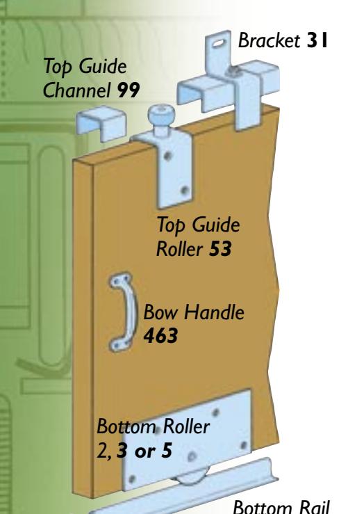
For straight sliding wood doors, the following are included:
- ◆ Top guide channel and brackets
- ◆ Top guide Rollers
- ◆ Bottom Rollers
- ◆ Bottom Rail
- ◆ Full range of accessories
For best operation, door width should not be less than half the door height. Wood doors should be framed, ledged and braced for industrial application or may be partly or fully glazed. The rollers should be positioned in the bottom rail of door clear of the joints with the stiles. 9" deep bottom
rails for No. 5 and No. 2 bottom rollers and 12" deep bottom rails for No. 3 bottom rollers are recommended.
Use the table below to estimate the approximate weight (pounds per square foot) of doors of different materials.
| Door Type | lbs./sq. ft. |
|---|---|
| Hollow Metal 18 ga | 4.6 lbs. |
| Hollow Metal 16 ga | 5.8 lbs. |
| Flush Wood, Particleboard Core | 4.8 lbs. |
| Flush Wood, Stave Core | 4.3 lbs. |
| Flush Wood, Mineral Core | 4.7 lbs. |
COMPOSITION
Top Guide Channel: Cold-rolled steel section.
Brackets : Pressed steel, painted finish. Single and double side wall fixing.
Top Guide Rollers : Steel electrozinc plated or painted aprons with nylon or
brass rollers.
Bottom Rollers : Cast iron wheels fitted with roller bearings and grease
nipples for lubrication. Supplied in painted finish. Cold-rolled steel section complete with couplers.
Bottom Rail: Door Stops
& Accessories: In painted or galvanized steel.
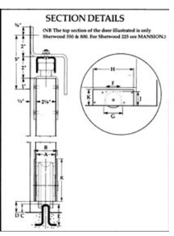
299 or 298
| All Dimensions in Feet and Inches | ||||
|---|---|---|---|---|
| System | 225 | 350 | 800 | |
| Α | 1 3 / 4 | 13/4 | 2 | |
| В | 2 | 21/8 | 21/2 | |
| С | 5/8 | 3/4 | 2 1 / 2 | |
| D | 1 | 1 | 1 3 / 16 | |
| Ε | 1 | 1 | 1 | |
| F | 21/2 | 41/2 | 5 3 / 8 | |
| G | 4 | 5 3 / 8 | 6 7 / 8 | |
| Н | 6 1 / 4 | 12 | 15 | |
| J | 2 5 / 8 | 3 3 / 4 | 5 1 / 8 | |
| K | 3 | 4 | 6 | |
| JOB NAME | QUOTE 🗅 | ORDER D |
|---|
| 1. Type of Track Required or Proposed: ☐Top Hung ☐Bottom | Roller |
|---|---|
| 2. Position of Door: ☐ Exterior (exposed) ☐ Interior (inside build | 0711711 |
| 3. Width of Opening: | 77.5 |
| 4. Height of Opening: | |
| 5. Proposed Number of Doors: | |
|
Other: |
| 7. Door Material: Solid Core Leadlined Glazed Metal Fra | ene Hollowcore if metal frome or lendlined, give details under question 16 |
| S. Door Weight: | |
|
to question 11 #YES, go to question 13 |
| (1) When Looking at the Door from the Inside of the Building, do Doors | Slide: Both Ways Left Only Right Only |
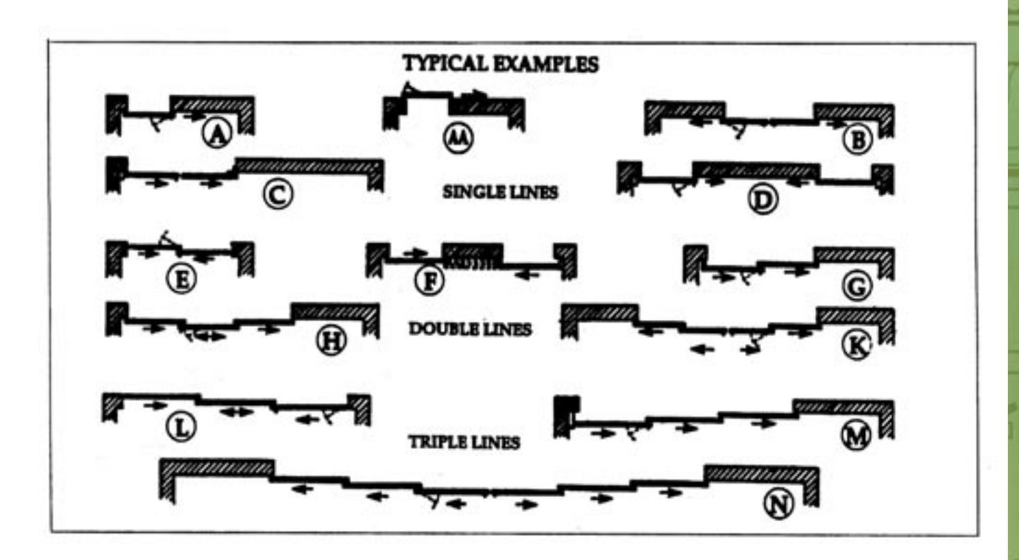
| Do the Doors Slide: ☐ Inside the Building (as in plan "A") | Outside the Building (as in plan "AA") |
| 2. How Many Lines of Track? One Two Three | 25.00 |
| 3 Bracket Mounting: Sidewall Overhead | |
| 4. Depth of Header: Width of Header: | |
| 5. Door Construction (metal doors): Angle Frame Box | Frame (depth of section 0-6") Channel Frame Special Frame/Leadlined |
| 6. Type of Floor: □ Asphalt □ Concrete □ Steel | No Floor (elevated opening) Wood Tile |
| 7. Type of Wheel Preferred (top hung only - tracks 305 & 307 have steel | only): Nylon Steet |
| 8 Security: Lock Bolt Unsecured Will | lock bolt be seen from the same side of door as doors hung – YES ee NO |
| 9. Number of Identical Openings: |
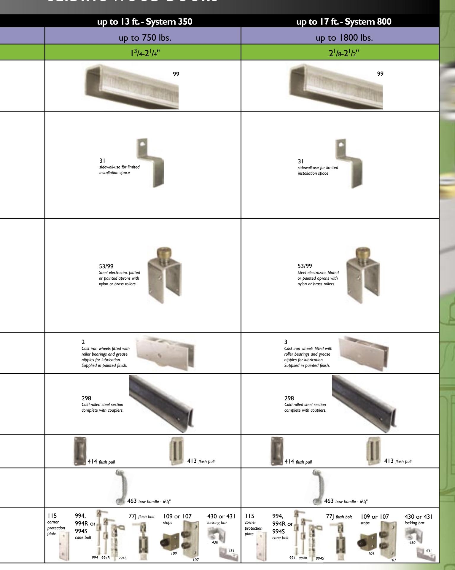
Sherwood HARDWARE FOR STRAIGHT
| Differ wood | ||||
|---|---|---|---|---|
| Max. Door Height | up to 11 ft System 225 | |||
| Max. Door Weight | up to 500 lbs. | |||
| DoorThickness | I 3 /4-2" | |||
| 5 | Top Guide Channel | 900 | ||
| Brackets (one bracket for every three feet of track) | 1/900 3/900 5/900 sidewall-use for limited overhead-use for limited sidewall dual track installation space installation space | |||
| Guides (two per door) | 54/900 Steel electrozinc plated or painted aprons with nylon or brass rollers | |||
| 1 | Bottom Rollers (two per door) |
5
Cast iron wheels fitted with roller bearings and grease nipples for lubrication. Supplied in painted finish. |
||
| Bottom Rail | 299 Cold-rolled steel section complete with couplers. | |||
| Flush Pull | 414 flush pull 413 flush pull | |||
| Bow Handle | 463 bow handle - 61/4" | |||
| Optional Extras | 115 994, 77J flush bolt 109 or 107 430 or 431 locking bar protection plate 994S cane bolt 109 or 107 430 or 431 | |||
SLIDING WOOD DOORS
Sherwood
FOR STRAIGHT SLIDING METAL DOORS
APPLICATIONS
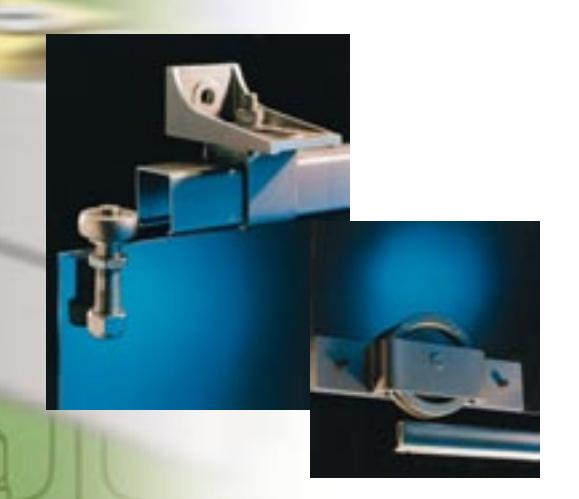
- ◆ The hardware is suitable for internal and external use in commercial and industrial buildings where the overhead structure will not support the weight of doors or where headroom is limited.
- ◆ Any number of doors may be used on single or multiple lines of rail sliding to one or both sides as required.
- Where doors are fitted externally, an overhang is recommended.
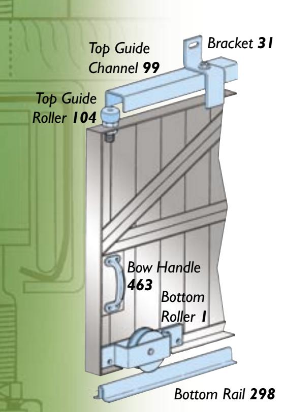
For straight sliding metal doors, the following are included:
- ◆ Top guide channel and brackets
- ◆ Top guide Rollers
- ◆ Bottom Rail
- ◆ Full range of accessories
For best operation, door width s the door height. The door is no
rack sizes) are available to suit doors of different weights up
using steel angle section and then clad with steel sheet or other suitable material except for Sherwood 3600 and 8000 hardware where the door would be constructed from steel channel section. Sherwood 3600 and 8000 hardware comprises standard and purpose made components as required. Bottom rollers can be supplied for mechanical operation
by geared chain wheel and winding handle.
Use the table below to estimate the approximate weight (pounds per square foot) of doors of different materials.
| Door Type | lbs./sq. ft. |
|---|---|
| Hollow Metal 18 ga | 4.6 lbs. |
| Hollow Metal 16 ga | 5.8 lbs. |
| Flush Wood, Particleboard Core | 4.8 lbs. |
| Flush Wood, Stave Core | 4.3 lbs. |
| Flush Wood, Mineral Core | 4.7 lbs. |
COMPOSITION (Except 3600 and 8000 hardware)
Top Guide Channel: Channel cold-rolled steel section.
Brackets: Pressed steel, painted finish. Single and double side wall fixing.
Top Guide Rollers: Steel electrozinc plated with nylon or steel rollers fitted
through top of door. Adjustable in height.
Bottom Rollers: Cast iron wheels fitted with roller bearings and grease
nipples for lubrication. Supplied in painted finish suitable
for welding or bolting.
Bottom Rail : Cold-rolled steel section complete with couplers. 3600
and 8000 hardware is manufactured to custom requirements. Composition is available on request.
Door Stops
& Accessories: In painted or galvanized steel.
All Dimensions in Feet and Inches
| System | 225 | 350 | 800 | 2000 | 3600 | 8000 |
|---|---|---|---|---|---|---|
| A | 3/8 | 3/4 | 3/4 | 11/4 | ||
| В | 3/8 | 2 | 2 | 13/8 | ||
| С | 11/2 | 11/2 | 11/2 | 33/8 | ||
| D | 3/4 | 3/8 | 3/8 | 1 | ||
| E | 1 | 1 | 1 3 / 16 | |||
| F | 11 /16 | 7/8 | 1 | 11/4 | 11/4 | |
| G | 2 | 2 | 2 | 2 | 21/2 | 21/2 |
| Н | 9 /16 | 7/8 | 7/8 | 1 | ||
| J | 5/8 | 3/4 | 1 | 1 | ||
| K | 1/8 | 1/4 | 1/4 | 3/4 | 3/4 | |
| L | 7 /16 | 1/2 | 1/2 | 1/2 | ||
| М | 1/2 | 1/2 | 1/2 | 5/8 | ||
| N | 1 3 / 16 | 13/4 | 2 7 / 16 | 33/8 | 5 | 8 |
| P | 3/4 | 11/8 | 11/4 | 11/4 | 3 | 3 |
| Q | 3 | 33/4 | 5 | 77/8 | ||
| R | 2 | 3 | 3 | 4 | ||
| S | 9 | 12 | 15 | 18 |
| QUOTE 🗅 | ORDER U |
|---|---|
| QUOTE 🗅 |
| to A | |
|---|---|
| Type of Track Required or Proposed: ☐Top Hung ☐Bottom I | Roller |
| 2. Position of Door: ☐ Exterior (exposed) ☐ Interior (inside building | (g) |
| 3. Width of Opening: | 77.55 |
| 4. Height of Opening: | |
| 5. Proposed Number of Doors: | |
| 6. Door Thickness (1-3/8" min 2-1/4" max.): | Other: |
| 7. Door Material: Solid Core Leadlined Glazed Metal Fran | ne Hollowcore if metal frame or leadlined, give details under question 16 |
| 8. Door Weight: | 10 00 00 00 00 |
| o question 11 #YES, go to question 13 | |
| 10. When Looking at the Door from the Inside of the Building, do Doors: | Slide: Both Ways Left Only Right Only |
| 11. Do the Doors Slide: ☐ Inside the Building (as in plan "A") | Outside the Building (as in plan "AA") |
| 12. How Many Lines of Track? ☐ One ☐ Two ☐ Three | 3.00.00 |
| 13. Bracket Mounting: Sidewall Overhead | |
| 14. Depth of Header: Width of Header: | |
| 15. Door Construction (metal doors): Angle Frame Box Fr | rame (depth of section 0.6") Channel Frame Special Frame/Leadlined |
| 16. Type of Floor: ☐ Asphalt ☐ Concrete ☐ Steel | No Floor (elevated opening) Wood Tile |
| 17. Type of Wheel Preferred (top hung only - tracks 305 & 307 have steel of | only): Nylon Steel |
| 18. Security: ☐ Lock ☐ Bolt ☐ Unsecured Will lo | ck bolt be seen from the same side of door as doors hung – YES or NO |
| 19. Number of Identical Openings: |
Sherwood hardware kit for straight
| SHCI WOOd | |||||
|---|---|---|---|---|---|
| Max. Door Height | up to 11 ft. | up to 13 ft. | |||
| Max. Door Weight | up to 500 lbs. | up to 750 lbs. | |||
| Door Thickness | l 3 /4-2" | 1 3 /4-2 1 /8" | |||
| 5 | SYSTEM NUMBER | 225 | 350 | ||
| Top Guide Channel | 900 | 99 | |||
|
Brackets (one bracket for
every three feet of track) |
I/900 sidewall-use overhead-us for limited for limited\ninstallation installation space space 5/900 sidewall dual track | 3 I Pressed steel painted finish. Single side wall fixing. | |||
|
Guides (two per door)
(four per door on 3600/8000 systems) |
I 04/900
Steel electrozinc plated with nylon or steel rollers fitted through top of door. Adjustable in height. |
I 04/99 Steel electrozinc plated with nylon or steel rollers fitted through top of door. Adjustable in height. | |||
| 1 |
Bottom Rollers
(two per door) |
5S Cast iron wheels fitted with roller bearings and grease nipples for lubration. Supplied in painted finish suitable for welding or bolting. | IS Cast iron wheels fitted with roller bearings and grease nipples for lubrication. Supplied in painted finish suitable for welding or bolting. | ||
| Bottom Rail | 299 Cold-rolled steel section complete with couplers. | 298 Cold-rolled steel section complete with couplers. | |||
| Bow Handle | 463 bow handle - 6 1 / 4 " | 463 bow handle - 61/4" | |||
| Optional Extras | 994, or 994S cane bolt flush pull 109 or 107 stops 109 107 |
994, or 994S
cane bolt flush pull 109 or 107 stops |
|||
SLIDING METAL DOORS
| up to 17 ft. | up to 25 ft. | up to 40 (3600) or 65 (8000) ft. |
|---|---|---|
| up to 1800 lbs. | up to 4400 lbs. | up to 8000 (3600) or 17500 (8000) lbs. |
| 21/8-21/2" | 21/4-23/4" | 6" minimum thickness |
| 800 | 2000 | 3600 or 8000 |
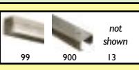
| 99 |
13
not shown |
not required |
| 3 | Pressed steel painted finish. Single side wall fixing. | I/13 sidewall single track | not required |
| I 04/99 Steel electrozinc plated with nylon or steel rollers fitted through top of door. Adjustable in height | 104/13 Steel electrozinc plated with nylon or steel rollers fitted through top of door. Adjustable in height. | 104S (not shown) Steel electrozinc plated with nylon or steel rollers fitted through top of door. Adjustable in height. |
| 3S Cast iron wheels fitted with roller bearings and grease nipples for lubrication. Supplied\nin painted finish suitable for welding or bolting. | 4SJ Cast iron wheels fitted with roller bearings and grease nipples for lubrication. Supplied\nin painted finish suitable for welding or bolting. | 3600 (not shown) Cast iron wheels fitted with roller bearings and grease nipples for lubrication. Supplied in painted finish suitable for welding or bolting. Made to suit door. Chain driven geared rollers also available. |
| 298 Cold-rolled steel section complete with couplers. | 298 Cold-rolled steel section complete with couplers. | 297 cold rolled steel section complete with couplers |
| 463 bow handle - 61/4" | 464 bow handle - 10114" | not required |
| 994, or 994S cane bolt flush pull 109 or 107 stops 994 9945 109 | 994, or 994S cane bolt flush pull 109 or 107 stops 109 109 107 | 994, or 994S cane bolt flush pull 109 or 107 stops 994 994 9945 109 |
Tangent
FOR FOLDING METAL OR WOOD DOORS
APPLICATIONS
- ◆ The hardware is suitable for commercial or industrial folding doors, folding windows and showroom doors.
- ◆ Up to six door panels can be hinged to a jamb fixed within the opening or behind a reveal.
- Alternatively free-floating units can be parked behind a reveal, units must be made up of four or five units for stability.
- ◆ A swinging pass door (for doors under 10' high) is obtained by using three or five panels hinged to jamb or an independently hung panel (see plan details).
- For doors over 10' high, a wicket door is recommended.
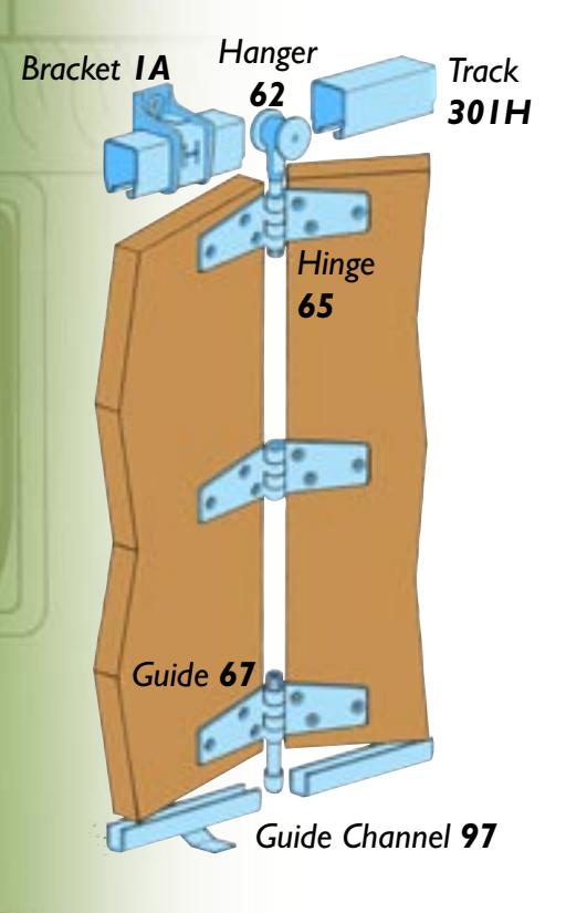
For folding metal or wood doors, the following are included:
- Support brackets and track
- Hangers
- Hinges
- Guides
- Bottom channel
- Full range of accessories
Four track sizes are vailable to suit doors of different weights up to 180 lbs
For smooth operation, no more than six door panels should be hinged together in one unit. Doors may be panelled or flush, glazed if required. Hinges should be fixed to framing
and joints of the door. Fittings are available in standard or deluxe finish which is polished or satin anodized aluminum.
Use the table below to estimate the approximate weight (pounds per square foot) of doors of different materials.
| Door Type | lbs./sq. ft. |
|---|---|
| Hollow Metal 18 ga | 4.6 lbs. |
| Hollow Metal 16 ga | 5.8 lbs. |
| Flush Wood, Particleboard Core | 4.8 lbs. |
| Flush Wood, Stave Core | 4.3 lbs. |
| Flush Wood, Mineral Core | 4.7 lbs. |
COMPOSITION
Track: Cold-rolled steel section hot-dip galvanized.
Brackets: Cast aluminum alloy or pressed steel, suitable for side
wall or overhead fixing. Closed brackets or end-clips
available for track ends.
Steel wheels fitted with maintenance free precision Hangers:
needle bearings sealed for life. Adjustable in height. Steel parts are rustproofed by electrozinc plating or painted, and hinge parts are in cast aluminum alloy, or painted cast iron. Deluxe finish hangers have polished
aluminum hinge parts.
In cast aluminum alloy (deluxe = S.A.A.) or painted cast iron. Hinges: Channel and Guides: Bottom channel steel section in three sizes, lugged for
concrete and drilled for drainage. Brass roller guides are mounted on alloy or cast iron hinge parts (deluxe = polished aluminum). Aluminum or brass channel is
available for deluxe applications. In painted or galvanized steel.
Bolts and Bow Handles: Flush Bolts and Pulls:
In satin anodized aluminum.
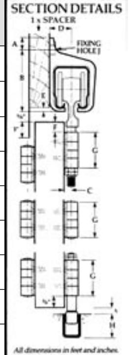
| All Dime | ensions | in | Feet | and | Inches |
|---|---|---|---|---|---|
| Track | 290 | 301/301H | 305 |
|---|---|---|---|
| Α | 1/2 | 3/4 | 1 |
| В | 25/8 | 3 13 / 16 | 5 1 / 2 |
| С | 7 /16 | 7 / 16 | 9 / 16 |
| D | 1 1 / 16 | 13/8 | 11/2 |
| Е | 1/4 | 1/4 | 3/8 |
| F | 3/8 | 5/8 | 5/8 |
| G | 21/4 | 21/4 | 31/4 |
| Н | 1 | 11/2 | 11/2 |
| J | 5 / 16 | 1/2 | 5/8 |
Tangent
HARDWARE FOR FOLDING
| I all Sc. | |||||
|---|---|---|---|---|---|
| Max. Door Size | up to 8 ft./2'8" wide | up to 8 ft./2'8" wide | up to 11 ft./3ft. wide | ||
| Max. Door Weight | up to 80 lbs. | up to 80 lbs. | up to 120 lbs. | ||
| Door Thickness | I 3 /8-2" | I 3 /8-2" | I 3 /4-2 1 /4" | ||
| 5 | SYSTEM | Standard 8 ft. | Deluxe 8 ft. | Standard II ft. | |
| Track | 290 | 290 | 301 | ||
| Brackets (one bracket for every three feet of track) Jointing Brackets available for joining two pieces of track at bracet (i.e. IAX/301) | I A/290 sidewall-use overhead- for limited use for \ninstallation limited \ninstallation space installation space 4R/290S overhead- suspended overhead- suspended use for ample \ninstallation space | I A/290 sidewall-use for limited\ninstallation space 4R/290S overhead- suspended suse for\nimited\ninstallation space 4R/290S overhead- suspended\nuse for ample\ninstallation space | I A/30 I sidewall-\nuse for limited\ninstallation space 4R/30 IS 4/30 IS 4/30 IS 4/30 IS 4/30 IS 4/30 IS 4/30 IS 4/30 IS 4/30 IS 4/30 I Serverhead-\nuse for limited\ninstallation space 4R/30 IS 4/30 I Serverhead-\nuse for ample\ninstallation space | ||
|
Hangers
(one every two doors) |
62K folding pivot hanger 63K pivot hanger | 62A/P folding pivot hanger- polished 63A/P pivot hanger- polished |
62A
folding pivot hanger 63A pivot hanger |
||
| 1 | Hinges | 65 In cast aluminum alloy or painted cast iron. | 403/2 403/3 In cast aluminum alloy (deluxe=SAA) or painted cast iron. | 65 In cast aluminum alloy or painted cast iron. | |
|
Guides
(one every two doors) |
67/89 68/89 Brass roller guides mounted on alloy or cast iron hinge parts | 67/94P 68/94P Brass roller guides mounted on alloy or cast iron hinge parts (deluxe = polished aluminum) | 67/97 68/97 Brass roller guides mounted on alloy or cast iron hinge parts | ||
| Guide Channel | 89 steel guide channel | 94A aluminum guide channel | 97 steel guide channel | ||
| Optional Extras | 414 413 flush pull pull cane 400 bolts\nin satin anodized aluminum 994 994R 994S 464 bow handle - 101/4" 863 bow handle - 51/4" | 414 flush pull flush pull cane bolts\nin satin anodized aluminum 464 bow handle - 101/4" 863 bow handle - 51/4" 77] 78 454 333 | 414 413 flush pull flush pull cane 400 bolts\nin satin anodized aluminum 994 994R 994S 464 bow handle - 10!1/4" 863 bow handle - 5!4" |
METAL OR WOOD DOORS
| up to 11 ft./3ft.wide | up to 12 ft./3ft.wide | up to 12 ft./3ft.wide | up to 15 ft./3ft.wide |
|---|---|---|---|
| up to 120 lbs. | up to 150 lbs. | up to 150 lbs. | up to 180 lbs. |
| 1 3 /4-2 1 /4" | I 3 /4-2 1 /4" | I 3 /4-2 1 /4" | I 3 /4-2 1 /4" |
| Deluxe I I ft. | Standard 12 ft. | Deluxe 12 ft. | Standard 15 ft. |
| 301 | 301H | 301H | 305 |
| 1A/301 sidewall-\nuse for limited\ninstallation space 4R/301S 4/301S 4/301S 4/301S 4/301 Serve de distallation space 4R/301S 4/301S 4/301 overhead-\ninstallation space 4A/301 overhead-\nuse for limited\ninstallation space | 1A/30 I sidewall-\nuse for limited\ninstallation space 4R/301S 4/301S 4/301S 4/30 I overhead-\ninstallation space 4R/301S 4/30 I overhead-\nuse for ample\ninstallation space\ninstallation space | 1A/301 sidewall-\nuse for limited\ninstallation space 4R/301S 4/301S 4/301S 4/301S 4/301 overhead-\nuse for limited\ninstallation space 4R/301s 4/301 overhead-\nuse for ample\ninstallation space | I A/305 sidewall-\nuse for limited\ninstallation space 4A/305 overhead-use for ample installation space 4R/305S overhead-use for ample installation space |
| 62A/P folding pivot hanger- polished 63A/P pivot hanger- polished |
62A
folding pivot hanger 63A pivot hanger |
62A/P folding pivot hanger- polished 63A/P pivot hanger- polished | 62C folding pivot hanger 63C pivot hanger |
| 403/2 403/3 In cast aluminum alloy (deluxe=SAA) or painted cast iron. | 65 In cast aluminum alloy or painted cast iron. | 403/2 403/3 In cast aluminum alloy (deluxe=SAA) or painted cast iron. | 65 In cast aluminum alloy or painted cast iron. |
| 67/94P 68/94P Brass roller guides mounted on alloy or cast iron hinge parts (deluxe = polished aluminum) | 67/97 68/97 Brass roller guides mounted on alloy or cast iron hinge parts | 67/94P 68/94P Brass roller guides mounted on alloy or cast iron hinge parts (deluxe = polished aluminum) | 67C/97 68C/97 Brass roller guides mounted on alloy or cast iron hinge þarts |
| 94A aluminum guide channel | 97 steel guide channel | 94A aluminum guide channel | 97 steel guide channel |
| 414 413 flush pull pull cane 400\nin satin anodized aluminum 464 bow handle - 101/4" 863 bow handle - 51/4" | 414 413 flush pull flush pull Cane bolts\nin satin anodized aluminum 794 994R 994S 464 bow handle - 1014" 863 bow handle - 514" | 414 413 flush pull flush pull | 414 413 flush pull cane 400 bolts\nin satin anodized aluminum 464 bow handle - 10114 863 bow handle - 5114" |
Tangent
FOR ROUND THE CORNER WOOD OR METAL DOORS
APPLICATIONS
- The hardware is suitable for commercial or industrial Tangent doors, windows and showroom doors.
- The doors slide clear of the opening and are parked along the side walls.
- Openings may be covered by any number of units sliding to one or both sides.
- Units should not be less than three panels nor more than six panels hinged together.
- The end panel under the curve normally forms an access swing door.
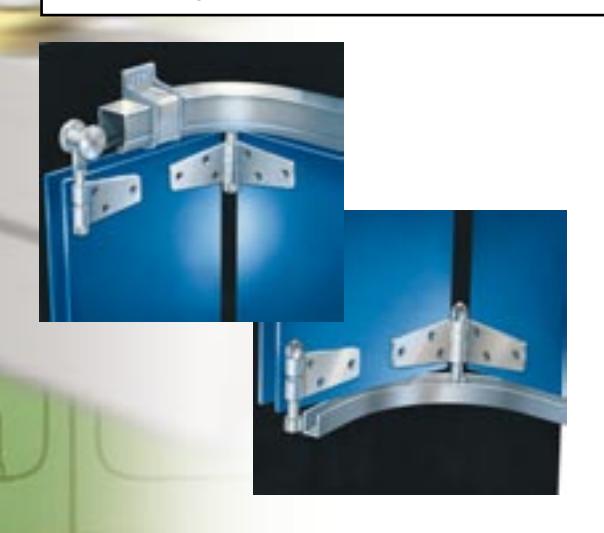
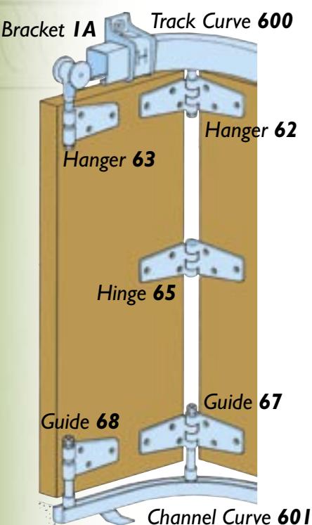
For "round-the-corner" metal or wood doors, the following are included:
- ◆ Support brackets and track
- ◆ Hangers
- ♦ Hinges
- ♦ Guides
- ♦ Bottom channel
- Full range of accessories
Four track sizes are all the size of different weights up to 180 lbs. 290 301 301H
For smooth operation, no more than six door panels should
be hinged together in one unit. Doors may be panelled or flush, glazed if required, with framing and joints designed to provide suitable fixing for hinges.
Use the table below to estimate the approximate weight (pounds per square foot) of doors of different materials.
| Door Type | lbs./sq. ft. |
|---|---|
| Hollow Metal 18 ga | 4.6 lbs. |
| Hollow Metal 16 ga | 5.8 lbs. |
| Flush Wood, Particleboard Core | 4.8 lbs. |
| Flush Wood, Stave Core | 4.3 lbs. |
| Flush Wood, Mineral Core | 4.7 lbs. |
COMPOSITION
Track and Track Curves: Brackets:
Cold-rolled steel section hot-dip galvanized.
Cast aluminum alloy or pressed steel, suitable for side wall or overhead fixing. Closed brackets or end-clips are available for track ends, and jointing brackets for
both ends of the track curve.
Hangers : Steel wheels are fitted with maintenance free precision
needle bearings sealed for life. Adjustable in height. Steel parts are rustproofed by electrozinc plating or painted, and hinge parts are in cast aluminum alloy, or painted cast iron. Deluxe finish hangers have polished
aluminum hinge parts.
Hinges: In cast aluminum alloy or painted cast iron.
Channel and Guides: Bottom channel st
Bottom channel steel section in three sizes, lugged for concrete and drilled for drainage. Brass roller guides
are mounted on alloy or cast iron hinge parts
Bolts, Stops and
Handles: In painted or galvanized steel.
All Dimensions in Feet and Inches
| iensions in | reet and inc | lies | |
|---|---|---|---|
| Track | 290 | 301/301H | 305 |
| Α | 1/2 | 3/4 | 1 |
| В | 2 5 / 8 | 3 13 / 16 | 5 1 / 2 |
| С | 7 /16 | 7 /16 | 9 / 16 |
| D | 1 1 / 16 | 13/8 | 11/2 |
| Ε | 1/4 | 1/4 | 3 /8 |
| F | 3/8 | 5/8 | 5/8 |
| G | 21/4 | 21/4 | 31/4 |
| H | 1 | 11/2 | 11/2 |
| 7 | 5 / 16 | 1/2 | 5 /8 |
| K | 1 | 11/2 | 11/2 |
| L | 5 / 16 | 1/2 | 5/8 |
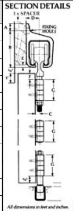
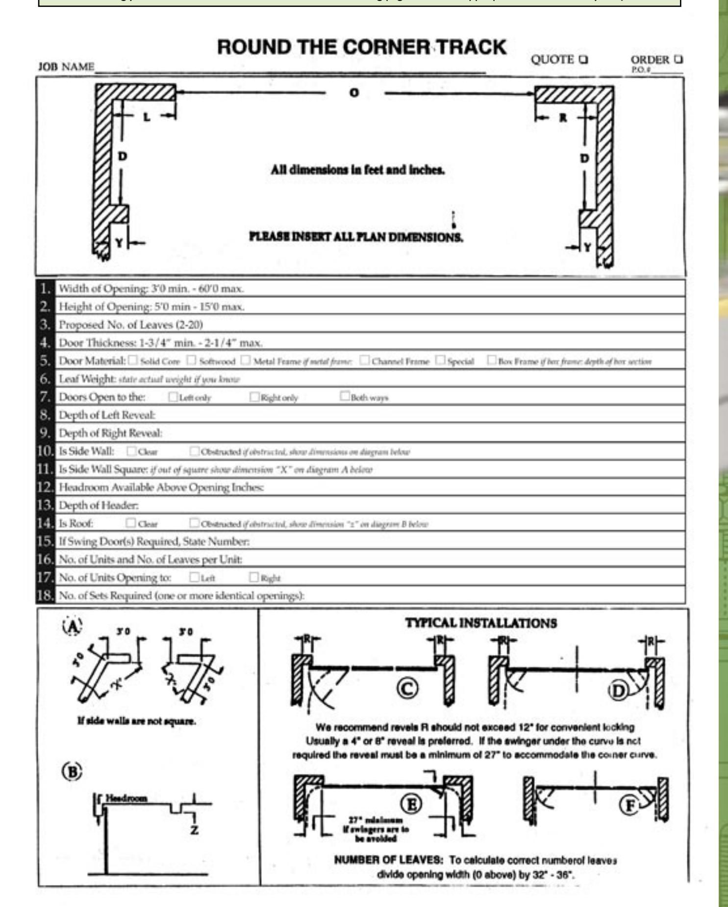
| Tangent hardware kit for round-the- | ||||
|---|---|---|---|---|
| Max. Door Height | up to 8ft System 290 | up to 11 ft System 301 | ||
| Max. Door Weight | up to 80 lbs. | 80-120 lbs. | ||
| Door Thickness/Width | 1 3 /8-2" thick, 32" wide | 1 3 /4-2 1 /4" thick, 36" wide | ||
| Track and Track Curve |
290
600K track curve |
301
600B track curve |
||
| Brackets (one bracket for every three feet of track) Jointing Brackets available for joining two pieces of track at bracet (i.e. IAX/301) | I A/290 sidewall-use for limited installation space space 4A/290 overhead-use for limited installation space 4R/290S overhead-use for ample suspended suspended suspended suspended | I A/30 I sidewall-use for limited\ninstallation space 4A/30 I overhead-use for ample\ninstallation space 4R/30 IS overhead- suspended\ninstallation space | ||
| Guides (two per door) | 67/89 68/89 Brass roller guides mounted on alloy or cast iron ninge parts | 67/97 68/97 Brass roller guides mounted on alloy or cast iron hinge parts | ||
| Hangers | 62K 63K folding pivot hanger pivot hanger (I per panel joint) (for end panel) | 62A 63A folding pivot hanger pivot hanger (I per panel joint) (for end panel) | ||
| Hinges | 65 In cast aluminum alloy or painted cast iron. | 65 In cast aluminum alloy or painted cast iron. | ||
|
Guide Channel/
Channel Curve |
89 steel guide 601/89 guide channel curve | 97 steel guide channel 601/97 guide channel curve | ||
|
Bow Handles, Flush
Pulls, Flush Bolts |
863 bow handle - 51/4" 463 bow handle - 61/4" | 863 bow handle - 51/4" 463 bow handle - 61/4" | ||
| Optional Extras | 414 flush pull 400 flush pull 994R cane bolt 109 or 107 stops 0ffset cane bolt | 109 or 107 stops 109 107 | ||
CORNER WOOD OR METAL DOORS
| up to 12 ft System 301H | up to 15 ft System 305 |
|---|---|
| 120-150 lbs. | 150-180 lbs. |
| 1 3 /4-2 1 /4" thick, 36" wide | 1 3 /4-2 1 /4" thick, 36" wide |
|
301H
600BH track curve |
305 600D track curve |
| IA/301 sidewoll-use for limited overhead-use for limited installation space 4A/301 overhead-use for ample installation space space 4R/301S overhead-use for ample suspended suspended suspended | I A/305 sidewall-use for overhead-use for limited installation space 4A/305 overhead-use overhead-use for ample installation space\ninstallation space 4R/305S overhead-use overhead-suspended suspended |
| 67/97 68/97 Brass roller guides mounted on alloy or cast iron hinge parts | 67C/97 68C/97 Brass roller guides mounted on alloy or cast iron hinge parts |
| 62A 63A folding pivot hanger pivot hanger (I per panel joint) (for end panel) | 62C 63C folding pivot hanger pivot hanger (I per panel joint) (for end panel) |
|
65
In cast aluminum alloy or painted cast iron. |
65
In cast aluminum alloy or painted cast iron. |
| 97 steel guide channel 601/97 guide channel curve | 97 steel guide channel 601/97 guide channel curve |
| 863 bow handle - 51/4" 463 bow handle - 61/4" 414 flush pull 400 flush pull 994R cane bolt | 463 bow handle - 6 1 / 4 " 413 flush pull 994R cane bolt |
| 109 or 107 994X offset cane bolt | 109 or 107 994X offset cane bolt |
Council 290-305
FOR END FOLDING WOOD PARTITION DOORS
APPLICATIONS
- The hardware is suitable for residential, commercial and public buildings where concealed fixing of the fittings is required.
- ◆ Only the neat flush pulls and bolts are visible on the face of the screen.
- ◆ Folding units should consist of an even number of panels up to a maximum of six hinged to jamb or anchored
- For wide openings, the center units may be "floating" and these should consist of four or six panels.
- ◆ A swing door independently hinged to post is recommended for easy access, or alternatively one can be added to a two or four panel unit. Avoid these on partitions over 10" high and if access is required a wicket door should be arranged.
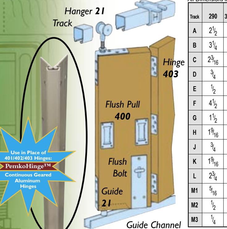
For flush end-folding wood doors, the following are included:
- Support brackets and track
- Hangers
- Hinges
- Guides
- Bottom channel
- Full range of accessories
Four track sizes are ailable to suit doors of different weights up to 180 lbs
For smooth operation, the recommended maximum number of panels in one unit is six hinged to jamb. If the panels are all of equal width and are required to be anchored at one end, Council "Flush fold pivot" hardware can be
used. Panels may be panelled, glazed or flush and should be constructed with solid top and bottom rails to provide a secure fixing for edge fitting, hangers and guides.
Use the table below to estimate the approximate weight (pounds per square foot) of doors of different materials.
| Door Type | lbs./sq. ft. |
|---|---|
| Hollow Metal 18 ga | 4.6 lbs. |
| Hollow Metal 16 ga | 5.8 lbs. |
| Flush Wood, Particleboard Core | 4.8 lbs. |
| Flush Wood, Stave Core | 4.3 lbs. |
| Flush Wood, Mineral Core | 4.7 lbs. |
COMPOSITION
Track Cold-rolled steel section hot-dip galvanized.
Cast aluminum or pressed steel electrozinc plated finish. Brackets:
Suitable brackets available for side wall or overhead fixing as well as closed brackets for each end.
Hangers: Fitted with maintenance free precision needle bearings
sealed for life. Adjustable in height. Steel wheels and other parts are electrozinc plated.
Aluminum alloy satin anodized finish. For economy, Hinges:
specify electrozinc plated steel hinges.
Brass rollers fitted to steel aprons which are electrozinc plated. Guides: Guide Channel Brass or aluminum drilled and counter-sunk for wood
or lugged for concrete.
Pivot Set (if required): Comprises a top pivot, standard bottom guide and
alternative sockets for wood or concrete floors.
Flush Pulls and Bolts: In satin anodized aluminum.
Bracket 3A
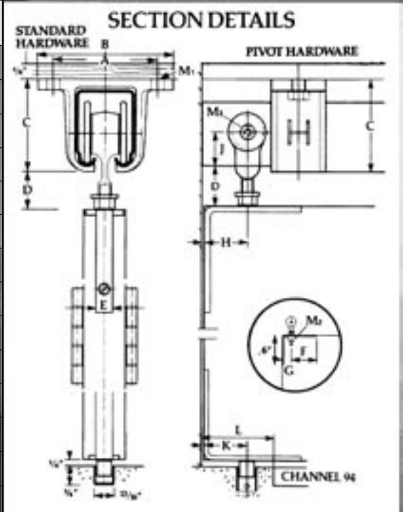
| 1 | All Di | mensions | in Feet a | nd Inches |
|---|---|---|---|---|
| Track | 290 | 301/301H | 305 | |
| Α | 21/2 | 4 | 5 | |
| В | 31/4 | 5 1 / 8 | 6 5 / 8 | |
| С | 2 3 / 16 | 33/8 | 43/4 | |
| D | 3/4 | 13/8 | 23/8 | |
| Е | 1/2 | 11 / 16 | 11 / 16 | |
| F | 41/2 | 5 1 / 4 | 5 1 / 4 | |
| G | 11/2 | 13/4 | 13/4 | |
| Н | 19/16 | 17/8 | ||
| J | 3/4 | 13/8 | ||
| K | 1 9 / 16 | 17/8 | ||
| L | 23/4 | 3 | ||
| M1 | 5 / 16 | 1/2 | 5 /8 | |
| M2 | 1/2 | 5/8 | 5 /8 | |
| М3 | 1/4 | 5/16 |
Council 290–305 hardware for end foldi
| Counci | |||
|---|---|---|---|
| Max. Door Height | up to 9ft System 290 | up to 11 ft System 301 | |
| Max. Door Weight | up to 80 lbs. | 80-120 lbs. | |
| Door Thickness/Width | 1 3 /8-1 3 /4" thick, 32" wide | 1 3 /4-2 1 /4" thick, 36" wide | |
| 5 | Track | 290 | 301 |
| Brackets (one bracket for every three feet of track) | I A/290 sidewall-use for overhead-use for limited installation space space 3A/290 4A/290 overhead-use for ample installation space space | IA/301 sidewall-use for overhead-use for limited installation installation space space AA/301 overhead-use for ample installation space | |
| Guides (two per door) |
21KR/94
guide |
2 I KR/94
guide |
|
| Hangers | 21K/S\nendfold hanger (I for every 2 panels) 21K/4N to be used adjacent to swing door | 21A/S\nendfold hanger (I for every 2 panels) bottom 21A/4S to be used adjacent to swing door | |
| Hinges, Pivots | 403/I 21K/P\nendfold pivot top bottom In cast aluminum alloy (deluxe=5. AA.) or painted cast iron. | 403/2 2 1 A/P\nendfold pivot In cast aluminum alloy (deluxe=S. AA.) or painted cast iron. | |
| Guide Channel | 94 brass 94A aluminum guide channel | 94 brass 94A aluminum guide channel guide channel | |
| Flush Pulls, Flush Bolts | 414 flush pull 400 flush pull 454 flush bolt 333 flush bolt | 414 flush pull 400 flush pull 454 flush bolt 333 flush bolt | |
| Optional Extras | II3R 21R I/290EC (not shown) end clip for 290 steel brackets (1A/290 end clips also available for aluminum brackets) | I I 3R 2 I R I / 30 I E C end clip for 30 I steel brackets (I A/30 I end clips also available for aluminum brackets) |
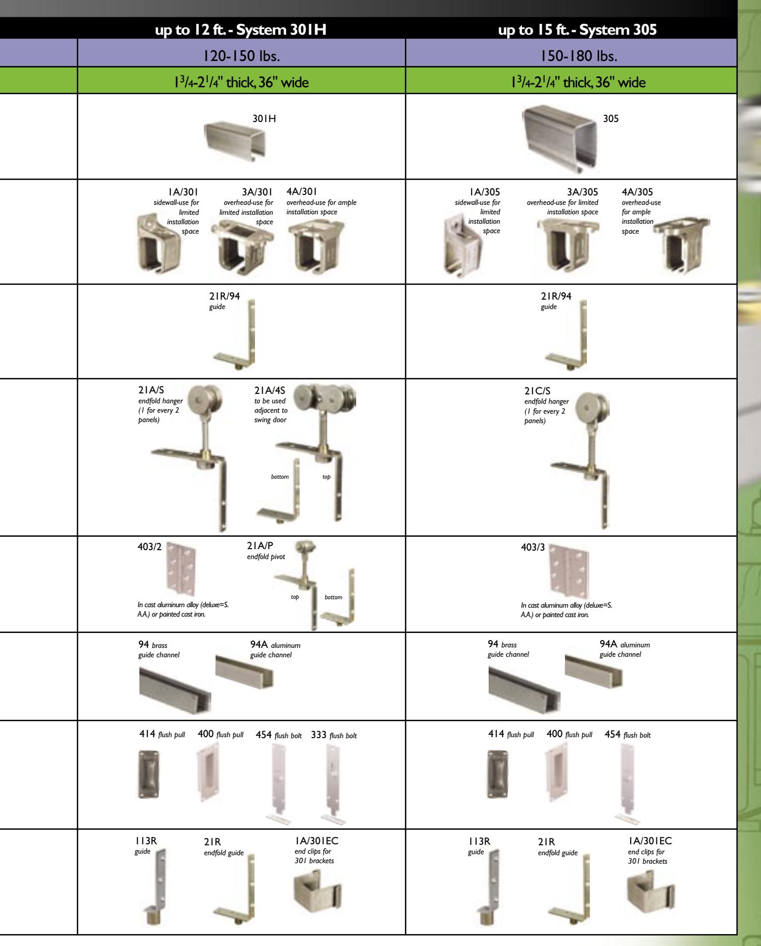
WOOD PARTITION DOORS
| _ | up to 12 ft System 301H | up to 15 ft System 305 |
|---|---|---|
| 120-150 lbs. | 150-180 lbs. | |
| 1 3 /4-2 1 /4" thick, 36" wide | 1 3 /4-2 1 /4" thick, 36" wide | |
| 301H | 305 | |
| IA/301 sidewall-use for overhead-use for overhead-use for overhead-use for overhead-use for ample installation space\ninstallation space space | I A/305 sidewall-use for overhead-use for limited limited installation space installation space\ninstallation space space A/305 overhead-use for ample installation space | |
|
21KR/94
guide |
21KR/94
guide |
|
| 21A/S\nendfold hanger (I for every 2 adjacent to swing door | 2 I C/S\nendfold hanger (I for every 2 panels) | |
| 403/2 2 | A/P\nendfold pivot In cast aluminum alloy (deluxe=S. AA) or painted cast iron. |
In cast aluminum alloy (deluxe=S.
AA) or painted cast iron. |
|
|
94 brass 94A aluminum
guide channel guide channel |
94 brass 94A aluminum guide channel guide channel | |
| 414 flush pull 400 flush pull 454 flush bolt 333 flush bolt | 414 flush pull 400 flush pull 454 flush bolt | |
| II3R 2IR I/30IEC end clips for 301 steel brackets (IA/301 end clips also available for aluminum brackets) | II3R 2IR guide endfold guide |
Council 290-305
FOR CENTER FOLDING WOOD PARTITION DOORS
APPLICATIONS
Track
- ◆ The hardware is suitable for residential, commercial and public buildings.
- Partitions are usually hung centrally under the lintel and fold to one or both sides, occupying a minimum of space during closing operation.
- The folding units should consist of an odd number of full panels with one half panel hinged to jamb.
- For wide openings, the center units may be "floating" and consist of five or seven panels in one unit.
- ◆ Where an access door is required this may be hung separately to the jamb and not form part of the folding unit, or a wicket door should be arranged in one panel.

- Support brackets and track
- Hangers
- Hinges
- Guides
- Bottom channel
- Full range of accessories
Four track sizes an vailable to suit doors of different weights up to 180 lbs

For smooth operation, the recommended maximum num-
ber of panels in one unit is five and a half hinged to jamb. Panels may be panelled, glazed or flush and should be constructed with solid top and bot-
Use the table below to estimate the approximate weight (pounds per square foot) of doors of different materials.
| Door Type | lbs./sq. ft. |
|---|---|
| Hollow Metal 18 ga | 4.6 lbs. |
| Hollow Metal 16 ga | 5.8 lbs. |
| Flush Wood, Particleboard Core | 4.8 lbs. |
| Flush Wood, Stave Core | 4.3 lbs. |
| Flush Wood, Mineral Core | 4.7 lbs. |
COMPOSITION
Cold-rolled steel section hot-dip galvanized. Brackets:
These are of cast aluminum or pressed steel. Suitable brackets are available overhead fixing
as well as closed brackets for each end.
Hangers: These are fitted with maintenance free
precision needle bearings sealed for life. Adjustable in height. Steel wheels and other parts are electrozinc plated.
Hinges: Aluminum alloy satin anodized finish. For
economy, specify electrozinc plated steel hinges.
Guides:
Brass rollers fitted to steel plates which are electrozinc plated.
Brass or aluminum drilled and
Channel: counter-sunk for wood or
lugged for concrete.
Flush Pulls and Bolts: In satin anodized
aluminum.
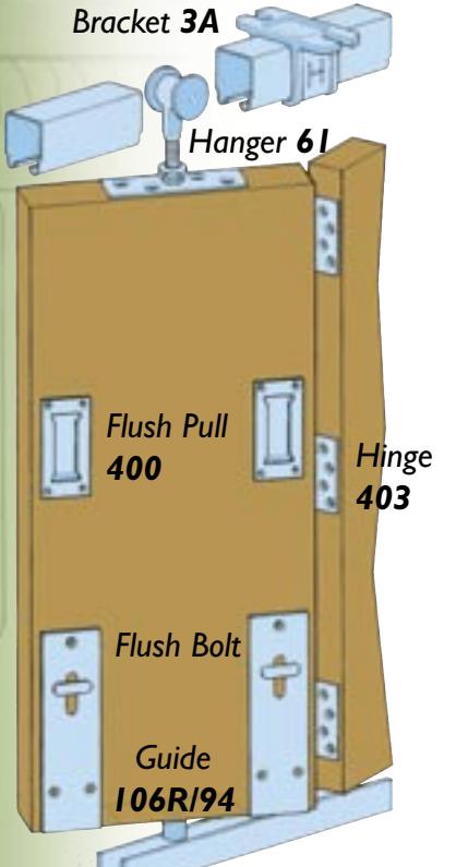
Guide Channel
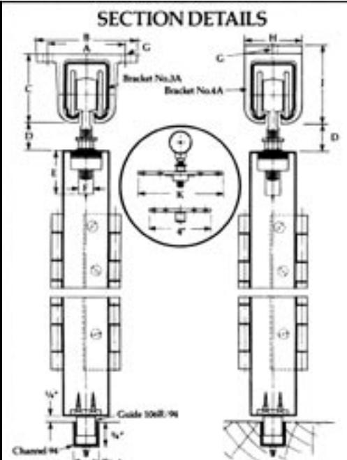
All Dimensions in Feet and Inches
| Track | 290 | 301/301H | 305 |
|---|---|---|---|
| Α | 21/2 | 4 | 5 |
| В | 31/4 | 5 1 / 8 | 6 5 / 8 |
| С | 2 3 / 16 | 3 3 / 8 | 4 3 / 4 2 3 / 8 |
| D | 3/4 | 13/8 | 23/8 |
| Е | 11/2 | 2 | 21/2 |
| F | 1/2 | 3/4 | 3/4 |
| G | 5 /16 | 1/2 | 5 /8 |
| Н | 17/8 | 3 | 31/4 |
| J | 25/8 | 3 3 / 4 | 5 3 / 8 |
| K | 51/2 | 71/4 | 91/2 |
Council 290-305 hardware for center
| Counci | 1 2/0-303 | |||
|---|---|---|---|---|
| Max. Door Height | up to 9ft System 290 | up to 11 ft System 301 | ||
| Max. Door Weight | up to 80 lbs. | 80-120 lbs. | ||
| Door Thickness/Width | 1 3 / 8 -1 3 / 4 " thick, 32" wide | 1 3 /4-2 1 /4" thick, 36" wide | ||
| 5 | Track | 290 | 301 | |
| Brackets (one bracket for every three feet of track) | I A/290 sidewall-use for overhead-use for limited installation space Space 3A/290 overhead-use for overhead-use for ample installation space space | I A/301 sidewall-use for overhead-use for overhead-use for limited installation space space space I A/301 3 A/301 4 A/301 overhead-use for ample installation space installation space | ||
| Guides (two per door) |
21KR/94
guide |
21R/94
guide |
||
| Hangers | 21K/S\nendfold hanger (I for every 2 panels) 21K/4N to be used adjacent to swing door | 21A/S\nendfold hanger (I for every 2 panels) bottom 21A/4S to be used adjacent to swing door | ||
| 1 | Hinges, Pivots | 403/I 21K/P endfold pivot top bottom In cast aluminum alloy (deluxe=S. AA.) or painted cast iron. | 403/2 2 I A/P\nendfold pivot In cast aluminum alloy (deluxe=S. AA.) or painted cast iron. | |
| Guide Channel | 94 brass 94A aluminum guide channel guide channel | 94 brass 94A aluminum guide channel guide channel | ||
| Flush Pulls, Flush Bolts | 414 flush pull 400 flush pull 454 flush bolt 333 flush bolt | 414 flush pull 400 flush pull 454 flush bolt 333 flush bolt | ||
| Optional Extras | II3R 2IR IA/30IEC end clips for 301 brackets | II3R 21R IA/301EC guide end clips for 301 brackets |
FOLDING WOOD PARTITION DOORS
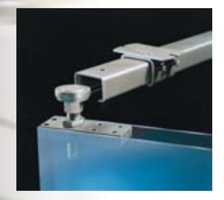
Arcade A70
FOR END AND CENTER FOLDING ALUMINUM AND WOOD SECTION DOORS
APPLICATIONS
High-quality bottom roller hardware and fittings for end and center folding aluminum section glazed for retail and display applications to a maximum leaf weight of 150 lbs.
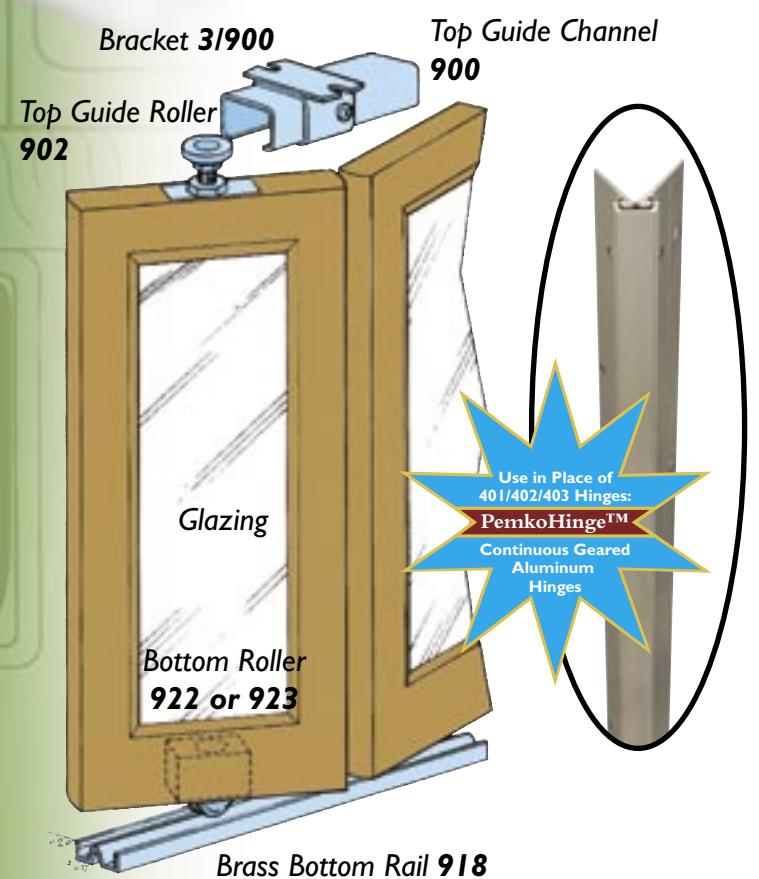
For end folding and center folding aluminum and wood partition doors, the following are included:
Top guide brackets
◆ Bottom rollers
◆ Top guide channel
Bottom railBack flap hinges
◆ Top guide rollers
◆ Full range of accessories
For best endfold operation, not more than 8 leaves should be hinged to one jamb; alternatively leaves may be floating in units of 6 or 8. Any access door should be hung separately to the jamb. For best centerfold operation, not more
than 71/2 leaves to be hinged to one jamb; alternatively leaves may be floating in units of 5 or 7. Any access door should be hung separately to the jamb.
Use the table below to estimate the approximate weight (pounds per square foot) of doors of different materials.
| Door Type | lbs./sq. ft. |
|---|---|
| Hollow Metal 18 ga | 4.6 lbs. |
| Hollow Metal 16 ga | 5.8 lbs. |
| Flush Wood, Particleboard Core | 4.8 lbs. |
| Flush Wood, Stave Core | 4.3 lbs. |
| Flush Wood, Mineral Core | 4.7 lbs. |
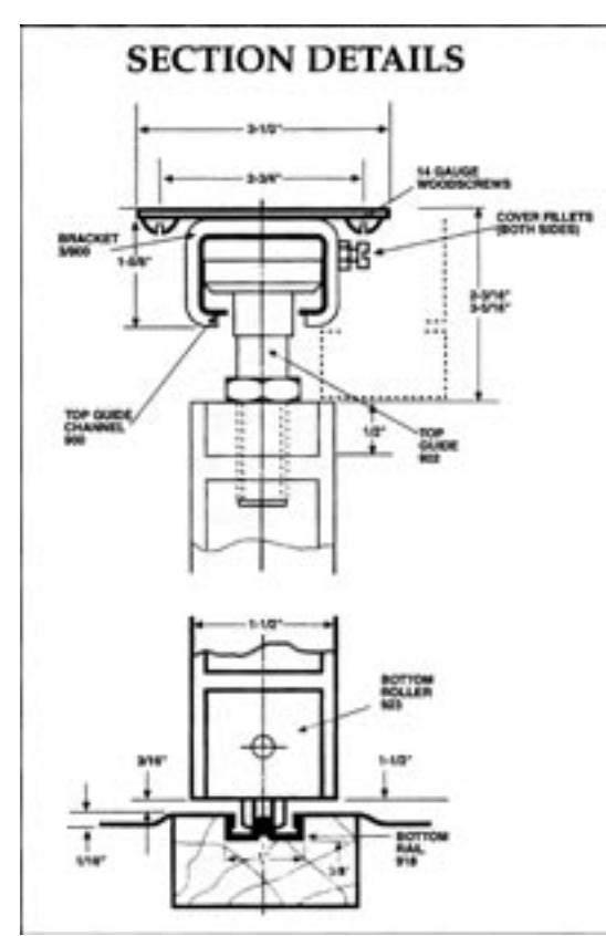
COMPOSITION
Top Guide Channel: 900 galvanized steel with safety lip.
Top Guide Brackets: Pressed steel zinc plated.
Top Guide Rollers: Fitted with adjustable nylon rollers. Vertical
adjustment is simple and positive. Bottom Rollers : Supported on thrust bearings.
Hinges: Proprietary hinges used to suit the aluminum rails and
stile used to construct the leaves.
Rail: Pre-drilled and countersunk for wood or lugging
into concrete.
Accessories: Flush Pulls, Flush Bolts and Locks.
Arcade A70 hardware for end and center
| Max. Door Weight up to 150 lbs. Top Guide Channel Brackets (fix every 3' max and at channel joints. Fix extra bracket where doors stack) Top Guide Rollers (one every two doors) Finsh Pull Flush Bolt Flush Bolt 150 lbs. \nup to 150 lbs. 1700 900 900 900 900 900 900 90 | |||
|---|---|---|---|
| Brackets (fix every 3' max and at channel joints. Fix extra bracket where doors stack) Top Guide Rollers (one every two doors) Pogament of fix and fix and fix and fix and fix and fix and fix and fix and fix and fix and fix and fix and fix and fix and fix and fix and fix and fix and fix and fix and fix and fix and fix and fix and fix and fix and fix and fix and fix and fix and fix and fix and fix and fix and fix and fix and fix and fix and fix and fix and fix and fix and fix and fix and fix and fix and fix and fix and fix and fix and fix and fix and fix and fix and fix and fix and fix and fix and fix and fix and fix and fix and fix and fix and fix and fix and fix and fix and fix and fix and fix and fix and fix and fix and fix and fix and fix and fix and fix and fix and fix and fix and fix and fix and fix and fix and fix and fix and fix and fix and fix and fix and fix and fix and fix and fix and fix and fix and fix and fix and fix and fix and fix and fix and fix and fix and fix and fix and fix and fix and fix and fix and fix and fix and fix and fix and fix and fix and fix and fix and fix and fix and fix and fix and fix and fix and fix and fix and fix and fix and fix and fix and fix and fix and fix and fix and fix and fix and fix and fix and fix and fix and fix and fix and fix and fix and fix and fix and fix and fix and fix and fix and fix and fix and fix and fix and fix and fix and fix and fix and fix and fix and fix and fix and fix and fix and fix and fix and fix and fix and fix and fix and fix and fix and fix and fix and fix and fix and fix and fix and fix and fix and fix and fix and fix and fix and fix and fix and fix and fix and fix and fix and fix and fix and fix and fix and fix and fix and fix and fix and fix and fix and fix and fix and fix and fix and fix and fix and fix and fix and fix and fix and fix and fix and fix and fix and fix and fix and fix and fix and fix and fix and fix and fix and fix and fix and fix and fix and fix and fix and fix and fix and fix and fix and fix and fix and fix and fix and f | Max. Folding Leaf Height | up to 12 ft Endfold System A70 | |
| Brackets (fix every 3' max and at channel joints. Fix extra bracket where doors stack) Top Guide Rollers (one every two doors) Hinges (three in height) Bottom Rollers (one every two doors) 922 ones and the receiving piece part downs and the receiving piece part downs and the receiving piece part downs and the receiving piece part downs and the receiving piece part downs and the receiving piece part downs and the receiving piece part downs and the receiving piece part downs and the receiving piece part downs and the receiving piece part downs and the receiving piece part downs and the receiving piece part downs and the receiving piece part downs and the receiving piece part downs and the receiving piece part downs and the receiving piece part downs and the receiving piece part downs and the receiving piece part downs and the receiving piece part downs and the receiving piece part downs and the receiving piece part downs and the receiving piece part downs and the receiving piece part downs and the receiving piece part downs and the receiving piece part downs and the receiving piece part downs and the receiving piece part downs and the receiving piece part downs and the receiving piece part downs and the receiving piece part downs and the receiving piece part downs and the receiving piece part downs and the receiving piece part downs and the receiving piece part downs and the receiving piece part downs and the receiving piece part downs and the receiving piece part downs and the receiving piece part downs and the receiving piece part downs and the receiving piece part downs and the receiving piece part downs and the receiving piece part downs and the receiving piece part downs and the receiving piece part downs and the receiving piece part downs and the receiving piece part downs and the receiving piece part downs and the receiving piece part downs and the receiving piece part downs and the receiving piece part downs and the received piece part downs and the received piece part downs and the received piece par | Max. Door Weight up to 150 lbs. | up to 150 lbs. | |
| Brackets (fix every 3' max and at channel joints. Fix extra bracket where doors stack) Top Guide Rollers (one every two doors) Hinges (three in height) Bottom Rollers (one every two doors) 922 ones and the receiving piece part downs and the receiving piece part downs and the receiving piece part downs and the receiving piece part downs and the receiving piece part downs and the receiving piece part downs and the receiving piece part downs and the receiving piece part downs and the receiving piece part downs and the receiving piece part downs and the receiving piece part downs and the receiving piece part downs and the receiving piece part downs and the receiving piece part downs and the receiving piece part downs and the receiving piece part downs and the receiving piece part downs and the receiving piece part downs and the receiving piece part downs and the receiving piece part downs and the receiving piece part downs and the receiving piece part downs and the receiving piece part downs and the receiving piece part downs and the receiving piece part downs and the receiving piece part downs and the receiving piece part downs and the receiving piece part downs and the receiving piece part downs and the receiving piece part downs and the receiving piece part downs and the receiving piece part downs and the receiving piece part downs and the receiving piece part downs and the receiving piece part downs and the receiving piece part downs and the receiving piece part downs and the receiving piece part downs and the receiving piece part downs and the receiving piece part downs and the receiving piece part downs and the receiving piece part downs and the receiving piece part downs and the receiving piece part downs and the receiving piece part downs and the receiving piece part downs and the receiving piece part downs and the receiving piece part downs and the receiving piece part downs and the receiving piece part downs and the received piece part downs and the received piece part downs and the received piece par | |||
| Top Guide Rollers (one every two doors) Flush Pull Top Guide Rollers (one every two doors) 1900 30900 30900 30900 30900 30900 30900 30900 30900 30900 30900 30900 30900 30900 30900 30900 30900 30900 30900 30900 30900 30900 30900 30900 30900 30900 30900 30900 30900 30900 30900 30900 30900 30900 30900 30900 30900 30900 30900 30900 30900 30900 30900 30900 30900 30900 30900 30900 30900 30900 30900 30900 30900 30900 30900 30900 30900 30900 30900 30900 30900 30900 30900 30900 30900 30900 30900 30900 30900 30900 30900 30900 30900 30900 30900 30900 30900 30900 30900 30900 30900 30900 30900 30900 30900 30900 30900 30900 30900 30900 30900 30900 30900 30900 30900 30900 30900 30900 30900 30900 30900 30900 30900 30900 30900 30900 30900 30900 30900 30900 30900 30900 30900 30900 30900 30900 30900 30900 30900 30900 30900 30900 30900 30900 30900 30900 30900 30900 30900 30900 30900 30900 30900 30900 30900 30900 30900 30900 30900 30900 30900 30900 30900 30900 30900 30900 30900 30900 30900 30900 30900 30900 30900 30900 30900 30900 30900 30900 30900 30900 30900 30900 30900 30900 30900 30900 30900 30900 30900 30900 30900 30900 30900 30900 30900 30900 30900 30900 30900 30900 30900 30900 30900 30900 30900 30900 30900 30900 30900 30900 30900 30900 30900 30900 30900 30900 30900 30900 30900 30900 30900 30900 30900 30900 30900 30900 30900 30900 30900 30900 30900 30900 30900 30900 30900 30900 30900 30900 30900 30900 30900 30900 30900 30900 30900 30900 30900 30900 30900 30900 30900 30900 30900 30900 30900 30900 30900 30900 30900 30900 30900 30900 30900 30900 30900 30900 30900 30900 30900 30900 30900 309000 30900 30900 30900 30900 30900 30900 30900 30900 309000 30900 30900 30900 30900 30900 30900 30900 30900 309000 30900 30900 30900 30900 30900 30900 30900 30900 3090 | 5 | Top Guide Channel | 900 |
| Hinges (three in height) Bottom Rollers (one every two doors) Bottom Rail Flush Pull Flush Bolt | channel joints. Fix extra | sidewall-use for limited overhead-use for limited | |
| Hinges (three in height) Bottom Rollers (one every two doors) Bottom Rail Plush Pull Flush Bolt | |||
| Bottom Rollers (one every two doors) Bottom Rail 922 for duminum doors for wood doors bottom rail 918 brass bottom rail Flush Pull 400 flush pull | Top Guide Rollers (one every two doors) |
comes with flat
mounting plate |
|
| Bottom Rollers (one every two doors) Bottom Rail 918 brass bottom rail Flush Pull Flush Bolt | 1 | Hinges (three in height) | 65/65P hinge |
| Flush Pull Flush Bolt | Bottom Rollers (one every two doors) | ||
| Flush Bolt | Bottom Rail | ||
| Flush Pull | 400 flush pull | ||
| Flush Bolt | 454 flush bolt |
FOLDING ALUMINUM AND WOOD SECTION DOORS
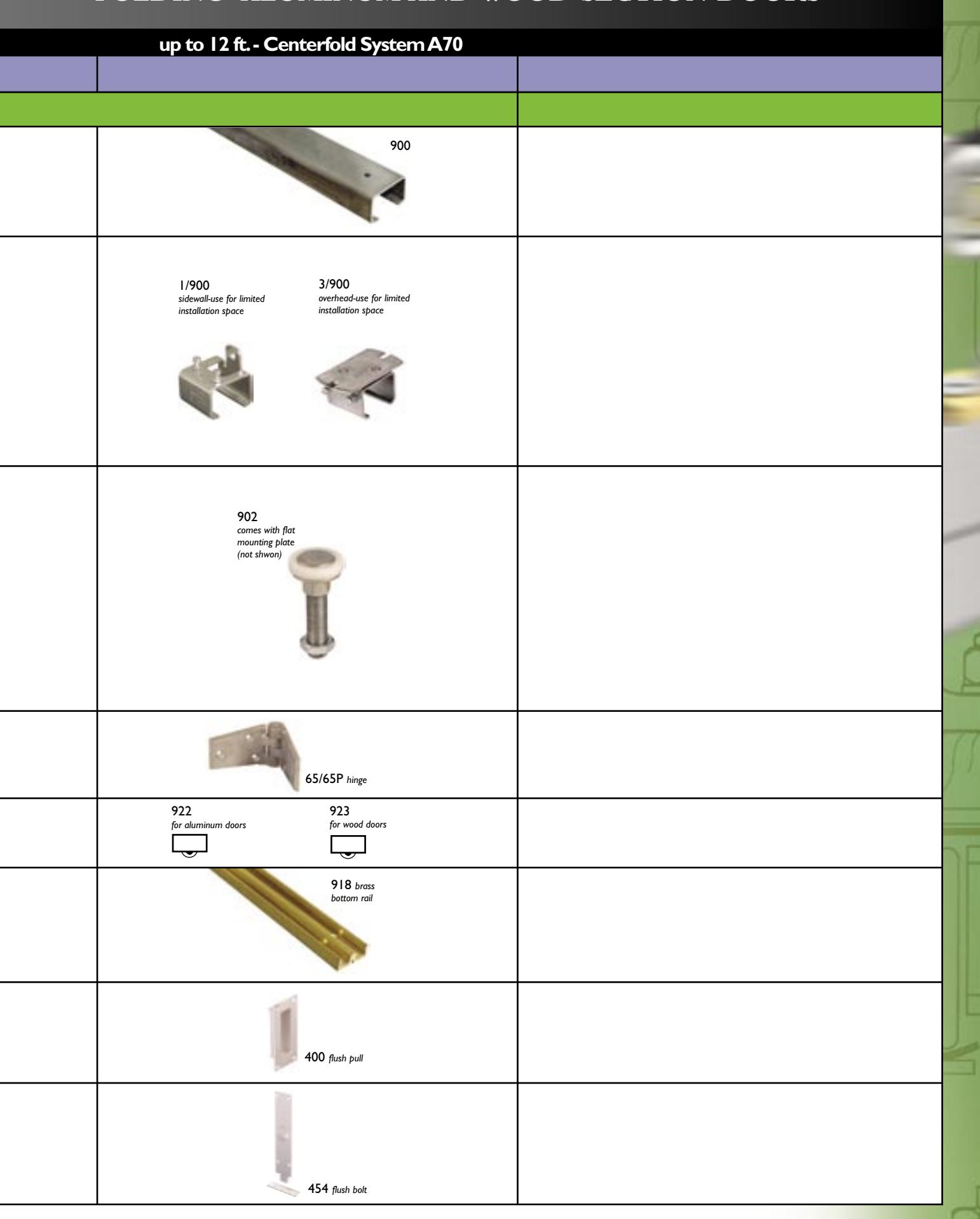
Overhead Runways
Track Curve
Track
Hanger
Hanger 58K/S
Hanger 76A/W
Bracket
Track 290
Henderson standard tracks, curves and brackets can be used together with a choice of specially adapted hangers to make a variety of overhead runway
systems. These are suited not only to the trans-
Five track sizes are available depending
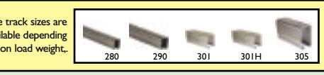
fer of load from one location to another, but also for more specialized applications such as industrial and vehicle curtains, cable carriers, safety runways for window cleaners of high buildings, and even gymnasium climbing ropes.
APPLICATIONS
- ◆ The hardware is suitable for factories, warehouses, commercial and public buildings and vehicles.
- ◆ For overhead transport runways layouts including curves are possible.
- ◆ These are usually attached to the roof support structure, using fixed or adjustable overhead fixing brackets spaced 2-3 ft. apart, but it is important that the overhead structure can support a moving load.
- ◆ Window cleaning runways are fitted to the outside of buildings designed with a parapet wide enough for a person to walk along.
- ◆ The specially punched track is normally fixed into a precast recess within the overhead concrete slab, using purpose designed bolt assemblies.
- ◆ A window cleaner (load weight 300lbs max) wearing an approved safety harness and lanyard attached to the hanger can be restrained through a 6 ft. fall, but the track and fittings must afterwards be inspected and if necessary replaced.
- ◆ Suitable for straight track applications only.
COMPOSITION
Track and
Track Curves: Cold-rolled steel section hot-dip galvanized. Brackets: These are cast aluminum or pressed steel electrozinc plated finish or painted.
Hangers: Steel wheels are fitted with maintenance free precision needle bearings sealed for life. All steel parts are electrozinc plated or painted.
Stops: In painted or galvanized steel.
Window Cleaning Safety System
Cable Carrying System
Overhead Transport System
Track Bracket Industrial Curtains
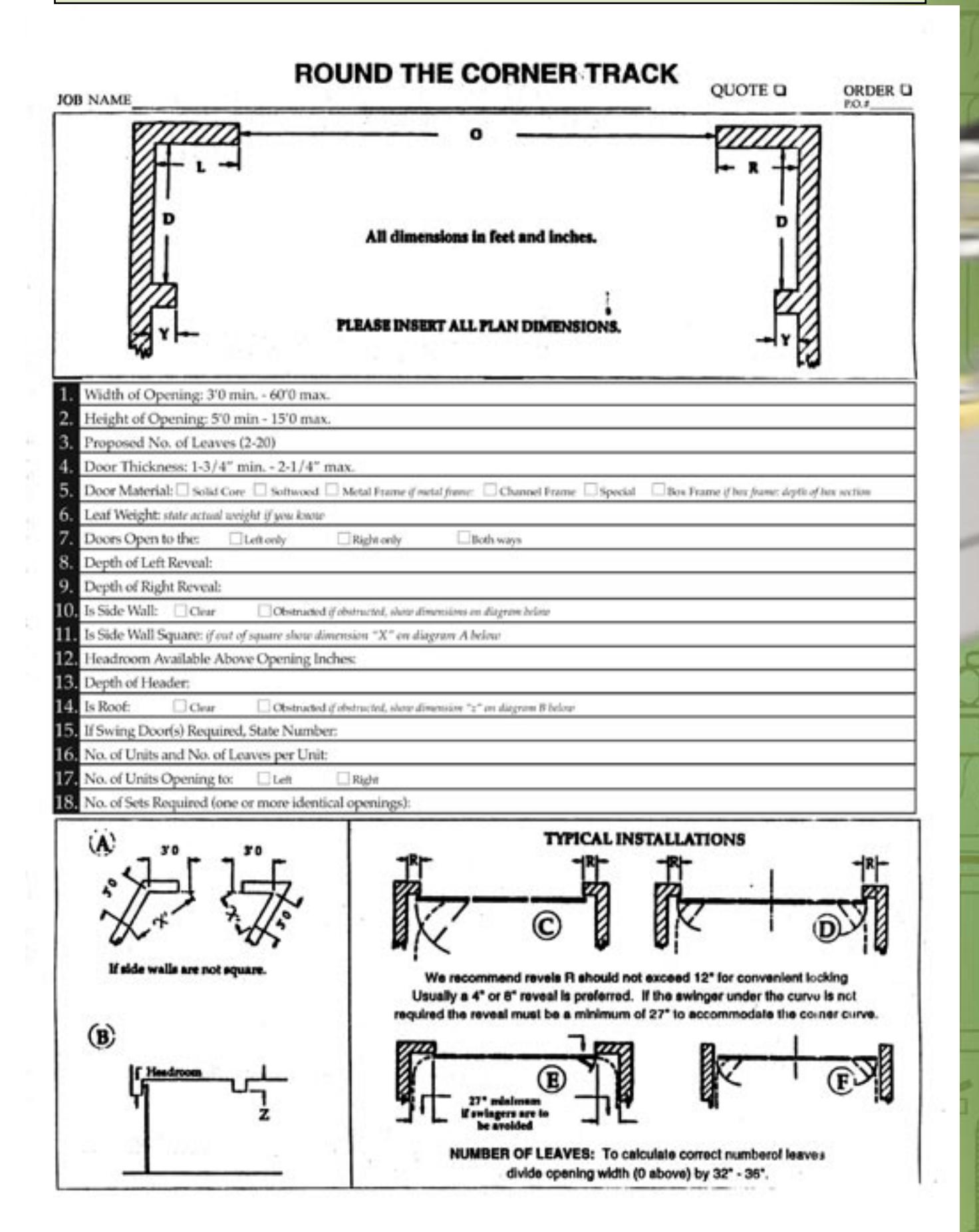
Overhead Runways
| Max. Load Weight | 0-500 lbs. | 0-440 lbs. | ll lbs. / 44 lbs. | |
|---|---|---|---|---|
| System Type | Overhead Transport (straight) | Overhead Transport (curved) | Industrial Curtains | |
| Track |
301
for 300 lbs load weight |
301
for 240 lbs load weight |
280
for 11 lbs load weight |
|
|
301H
for 400 lbs load weight |
301H
for 300 lbs load weight |
|||
|
305
for 500 lbs load weight |
305
for 440 lbs load weight |
290
for 44 lbs load weight |
||
|
Track Curves
(23" radius) |
600B
for 240 lbs load weight |
280TC
(not shown) for 11 lbs load weight |
||
| not required |
600BH
for 300 lbs load weight |
|||
|
600D
for 440 lbs load weight |
600K
for 44 lbs load weight |
|||
|
Brackets
(one bracket for every three feet of track and at |
3A/301
3A/305 overhead fixed overhead fixed |
3A/301
3A/305 overhead fixed overhead fixed |
4R/280S
3A/290 overhead fixed overhead fixed-for 44 adjustable-for lbs load weight 11lbs. load weight |
|
|
track joints)
Jointing Brackets |
4R/301S
4R/305S |
4R/301S
4R/305S |
4R/290S | |
|
available for joining
two pieces of track at bracet (i.e. 1AX/301) |
overhead
overhead fixed fixed adjustable adjustable |
overhead
overhead fixed fixed adjustable adjustable |
overhead fixed
adjustable-for 44 lbs. load weight |
|
| Hangers |
76/301 (can also use 71A)
for 400 lbs load weight |
76/301
for 300 lbs load weight |
288H
for 11 lbs load weight |
|
|
76/305 for 500
lbs load weight |
76/305 for 440
lbs load weight |
58K/S for 44 lbs | ||
| load weight | ||||
Overhead Transport Systems
| ll lbs. / 44 lbs. | 44 lbs. | 90 lbs. | 300 lbs.* | 440 lbs. | |
|---|---|---|---|---|---|
| Vehicle Curtains | Cable Carriers | Window Cleaning | Climbing Rope | ||
| 290 | 290 |
301H
305 |
301H | ||
| not required | not required | not required | not required | ||
|
3A/290
overhead fixed 4R/290S overhead fixed adjustable |
3A/290
overhead fixed 4R/290S overhead fixed adjustable |
M12 Bolts
not shown |
4A/301
overhead fixed 4R/301S overhead fixed or overhead fixed adjustable |
||
| 55MV/S | 56K/N | 76A/W | 70GYM | ||
* Capacity when load is dropped through 6 ft.
Titan FOR SLIDING CANTILEVER GATES
FOR SLIDING
APPLICATIONS
- ◆ Gates into security-fenced areas (e.g. airports, storage), factory entrances, condominiums and residences.
- ◆ Gates over railway lines or uneven surface roadways.
- These gates are best constructed in welded steel square tubing to your own design giving better security than round tube and chainlink gates.
- ◆ Opening width and gate weight determine the length of overhang required and track and roller type to use.
- There should be enough space available to slide the gate and overhang clear of the opening.
- Rollers should be mounted on substantial concrete footings, as wide apart as possible on the overhang.
- Titan can also be used for doors, where no overhead support exists for a sectional or shutter door to be fitted.
701
Titan cantilever hardware suits sliding metal gates. The track is fixed to the base of the gate, which runs on a pair of rollers ground-fixed to one
side of the opening. This leaves the roadway
Two track sizes are available to suit openings up to 32 ft. wide
710 (not shown) holds up to 2000 lbs. if manually operated
700 (not shown) holds up to 1200 lbs. if power operated.
free from any obstructions, especially top or bot-tom rails, which easily get blocked, damaged or can upset forklift loads. The heavy-duty rollers are hidden within the rail for maximum security and weather protection.
COMPOSITION
Track Cold-rolled galvanized steel section in 20 ft. lengths. Rollers:
Steel wheels with precision ball bearings mounted on height-adjustable ground plates. All parts are
7030
Wall-Concreted
709 and 104/709
galvanized or painted.
End Rollers: Steel ball bearing wheel with clamp-plate for
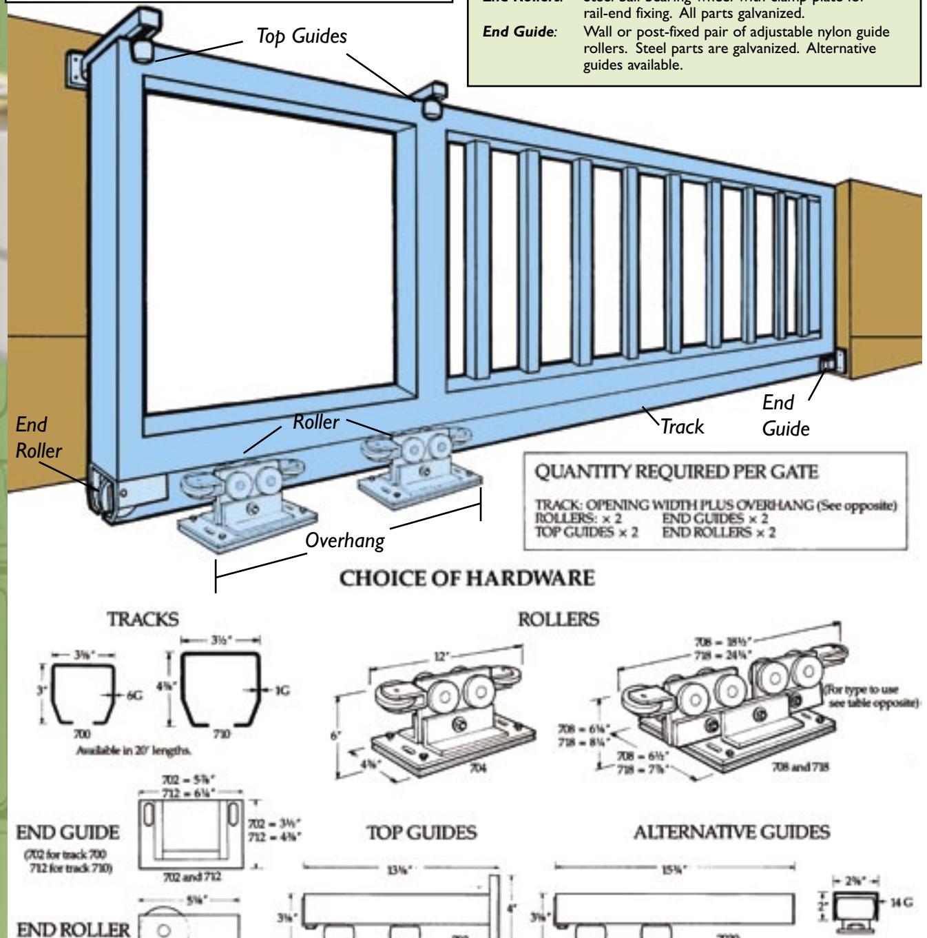
203
HOW TO CHOOSE YOUR HARDWARE: Choose gate type, manual or automatic. Read across to required gate opening width, then read downward to estimated gate weight. Shaded area indicates roller type and overhang length required.
Use a pair of rollers No. 704 and track No. 700 Use a pair of rollers No. 708 and track No. 700 Use a pair of rollers No. 718 and track No. 710
| MANUAL | OPENING WIDTH (ft) | |||||||
|---|---|---|---|---|---|---|---|---|
| GATE WEIGHT: | 400lbs. | |||||||
| 600lbs. | ||||||||
| 800lbs. | ||||||||
| 1000lbs. | ||||||||
| 1200lbs. | ||||||||
|
1400lbs.
1600lbs. |
||||||||
| 1800lbs. | ||||||||
| 2000lbs. | ||||||||
| AUTOMATIC | OPENING WIDTH (ft) | |||||||
|---|---|---|---|---|---|---|---|---|
| GATE WEIGHT: | 300lbs. | |||||||
| 400lbs. | ||||||||
| 500lbs. | ||||||||
| 600lbs. | ||||||||
| 700lbs. | ||||||||
| 800lbs. | ||||||||
| 900lbs. | ||||||||
| 1000lbs. | ||||||||
|
1100lbs.
1200lbs. |
||||||||
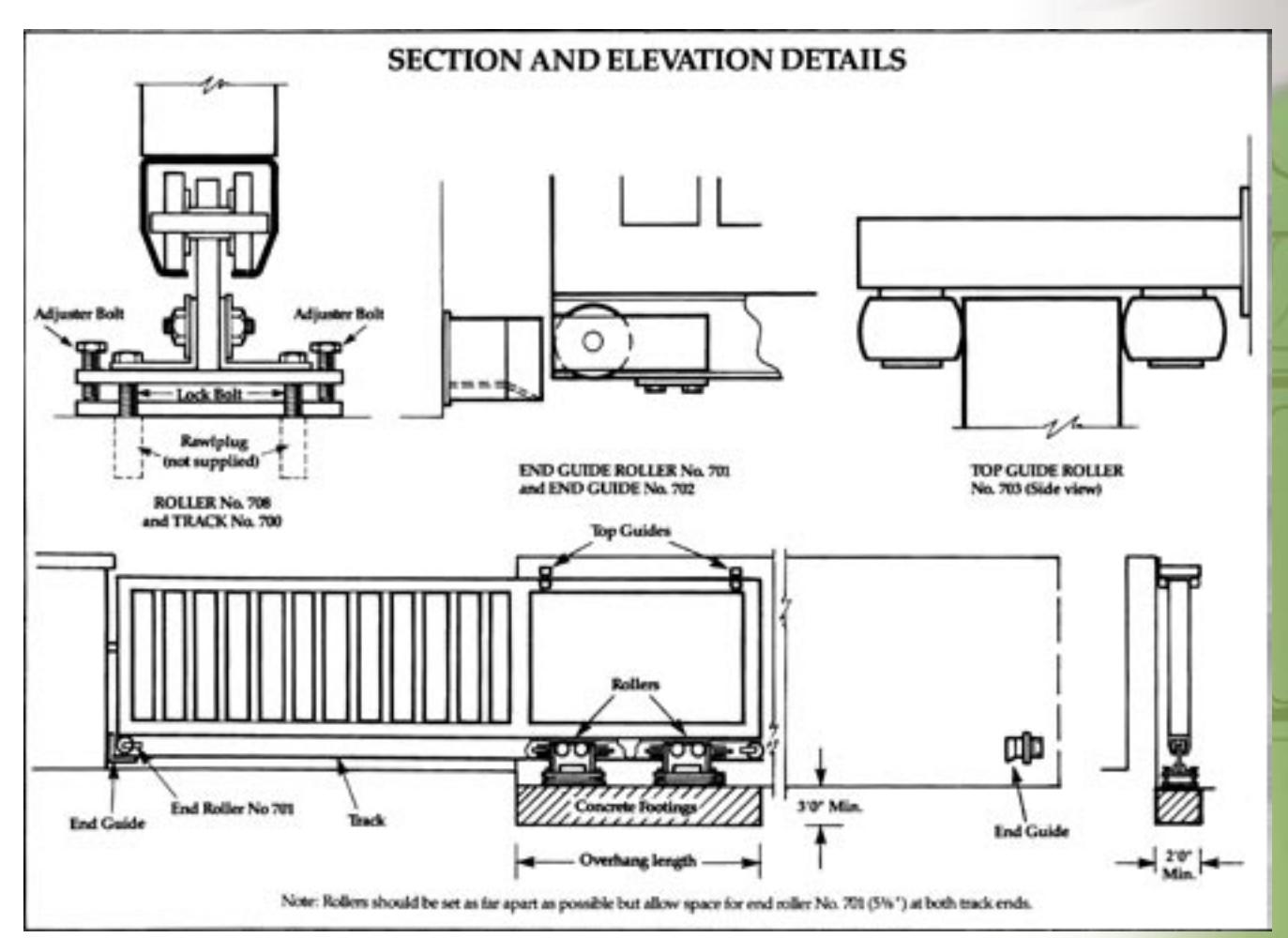


VENTURA CALIFORNIA
P.O. BOX 3780 VENTURA, CA 93006 TELEPHONE: 800.283.9988 FAX: 800.283.4050
WHITTIER CALIFORNIA
12251 EAST COAST DRIVE .. WHITTIER, CA 90601 TELEPHONE: 800.283.9988 FAX 800.283.4050
MEMPHIS TENNESSEE
P.O. Box 18966 MEMPHIS, TN 38181-0966 TELEPHONE 800,824 3016 FAX: 800.243.3656
#FM AUG
PEMBALES@PEMKO.COM
WEB
WWW.PEMKO.COM
HENDERS


INVESTOR IN PEOPLE