PS210 Installation Instruction
Open the original PDF document
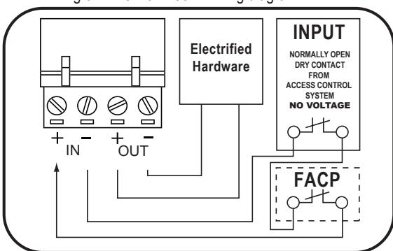
View PDFConnecting to the Fire Alarm Link (if needed)
- 1 Shut off breaker supplying AC power to the power supply.
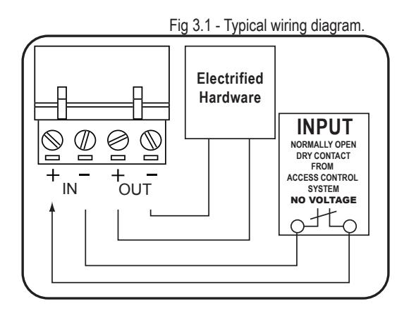
- 2 Wire your exit device(s) per the diagram(s).
NOTE: NO VOLTAGE ON INPUTS...DRY CONTACT ONLY
3 Restore power to power supply and trigger the device(s) to make sure they are working correctly.
Fig 3.2 Fire Alarm tie-in wiring diagram.
| TROUBLESHOOTING | ||
|---|---|---|
| Symptom | Possible Cause | Solution |
|
•
EL Exit device can't fully retract latch |
Possibility 1- Wire gauge from power
supply to exit device too small |
Check with your device manufacturer's wiring
specifications. |
|
Possibility 2- Distance from Power
Supply. to exit device is too far |
Check with your device manufacturer's wiring
specifications. |
|
|
Possibility 3- Exit device out of
adjustment |
Re-adjust exit device according to manufacturer's
mechanical recommendations. |
|
|
Green channel LED won't
• light up, channel isn't working |
Possibility 1- Dead short or overload |
Shut off power, detect short, restore power,
channel will reset. |
|
Possibility 2- Bad solenoid in exit device,
or defective interface device between solenoid and power supply. |
Check solenoid coil resistance and compare to
manufacturer spec. If not close, contact service representative. |
|
|
•
Power supply not working and red LED not lit. |
Possibility 1- AC fuse blown |
Replace fuse with 2A Slow Blow 250VAC
5mm x 20mm |
| Possibility 2- Short Circuit |
If replacement fuse has blown then there
is likely a short circuit in the board & it will need to be replaced. |
|
Installation Instructions PS210

DESCRIPTION
The PS210 power supply is a regulated, linear power supply rated at 1.5 Amps continuous but designed to provide the brief current surge required by 24VDC for electrified locking hardware: locksets, strikes, maglocks, and latch retraction devices.
SPECIFICATIONS
- Input voltage: 120 VAC, 60Hz, 2 Amp Input fuse
- Output voltage: Regulated 24VDC +/- 10%.
- Current Rating: 1.5 Amps continuous; 2 Amp Boost @ 20% duty cycle
- UL294 Sixth edition
- Class 2 Rated power limited output
- Input: 1 independent, solid-state input triggered by N.C. dry contact
- Solid-State Output: 1 Auto Resetting rated 1.5 Amp
- Enclosure: 11"W x 11"H x 4"D
- AC Fuse Type: 5mm x 20mm: rated @ 2 Amp 250VAC
- LEDs: Red = A/C Power Indicator, Green = D/C Output Indicator,
- Temperature Range: 0 to 49° C
- Maximum humidity: 85%
- Made in USA
- UL294 (6e) Security Levels:
Destructive Attack: Level I
Line Security: Level I
Endurance: Level IV Standby Power: Level I

Mounting Notes
- 1. For UL Installations, the power supply must be installed in the protected area within an Access Controlled room
- 2. Must be Installed within accordance with the National Electrical Code, ANSI/NFPA 70.
- 3. Must be Installed within accordance with Local authority having jurisdiction.
-
4. The AC input wiring shall
- a. be in conduit.
- b. be minimum No. 18 AWG wire.
- c. maintain ¼ inch spacing between non power-limited wiring, and
- d. be fail safe to meet the requirements of NFPA 101, Paragraph 7.2.1.6.
STEP 1 - Mount the power supply
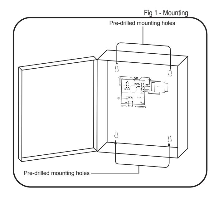
- 1. Find a cool and dry location to mount the power supply.
-
2. Using the four mounting holes in the power supply box, secure the box to a wall or other solid surface.
- (Note: The box is designed & approved for indoor use only.)
- 3. Proceed to step 2.
STEP 2 - 120VAC wiring connection
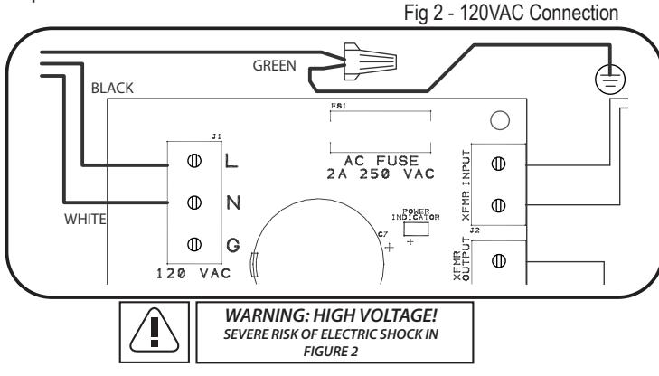
- 1. Make sure 120VAC service is off at power supply PS210 (Breaker should be shut off).
- 2. Make sure 120VAC supply wire is rated at 90° C or higher.
- 3. Connect 120VAC supply wire to the terminal block. Connect ground to pigtail attached to enclosure.
- 4. Restore AC power to power supply. Red LED should now be on.
- 5. Proceed to step 3.
STEP 3 - Wiring the Electrified Locking Hardware
1. Shut off breaker supplying AC power to the power supply.
NOTE: NO VOLTAGE ON INPUTS...DRY CONTACT ONLY
- 2. Using wiring diagram in fig 3.1, wire your exit devices.
- 3. Restore power to power supply and trigger exit devices to make sure they are working correctly.