PD25-M RIM Installation Instruction
Open the original PDF document
View PDF

PD25-M-RIM
INSTALLATION INSTRUCTIONS



The PD25-M-RIM (PD26 Mechanical) is our architectural grade 1 exit device. Electrified it comes equipped with motorized latch retraction utilizing our PTS "Push to Set" technology.
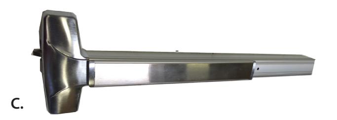
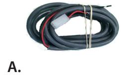
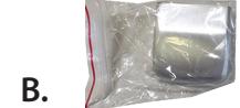
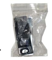
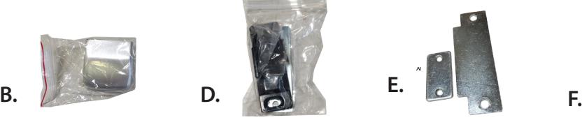
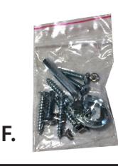
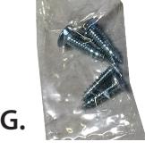
PD25 Includes
- A. 6' 2-Pin Power Lead (not included on PD26)
- B. End Cap
- C. PD25-M Device w/ MM Module
- D. Strike
- E. Shim Plates
- F. Screw Pack #1
- G. Screw Pack #2
Tools Required
• Cordless Drill

TECHNICAL INFORMATION
S PECIFICATIONS
- Input Voltage: 24VDC +/- 10%
- Wire gauge: Minimum 18 gauge
- Direct wire run no relays or access control units in-between power supply & module
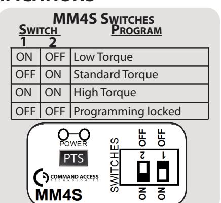
Low Torque Mode
- Average Latch Retraction Current: 600 mA
- Average Holding Current: 150 mA
Standard Torque Mode- Ships Standard
- Average Latch Retraction Current: 900 mA
- Average Holding Current: 215 mA
High Torque Mode
- Average Latch Retraction Current: 2 Amp
- Average Holding Current: 250 mA
OPTIONAL
REX SWITCH
Rating: .5A @24VAC
Configuration:
Green - Common (C)
BLUE - NORMALLY OPEN (NO)
Gray - Normally Closed (NC
SETTING PTS
**Important Info** Make sure to set PTS before finishing installation!
- Step 1- Select your preferred torque mode (ships in standard torque) Press the device push pad to the desired setting. (Recommend to fully depress and release 5%, giving the device a little room for changing door conditions.)
- Step 2- While depressing the push pad, apply power. (i.e. presenting the credential to the reader).
- Step 3- Continue to keep pad depressed, the device will beep 6 times. After the beeps have stopped, release the pad and now the adjustment is complete. If not to your liking repeat the three steps. That's all there is to it.
- Step 4 Once you found the right location, switch the dip switches to off to lock in programming.
Troubleshooting & Diagnostics
| BEEPS | EXPLANATION | Solution |
|---|---|---|
| 2 Beeps | Over Voltage | > 30V unit will shut down. Check voltage & adjust to 24 V. |
| 3 Beeps | Under Voltage | < 20V unit will shut down. Check voltage & adjust to 24 V. |
| 4 Beeps | Failed Sensor | Verify all 3 sensor wires are installed correctly. Replace sensor if problem persists by contacting office. |
| 5 Beeps |
Retraction or Dogging
failure |
|
| 6 Beeps | Push to Set | Device is recording it's new position and power mode after the 6th beep. |
2

RECOMMEND POWER SUPPLIES:
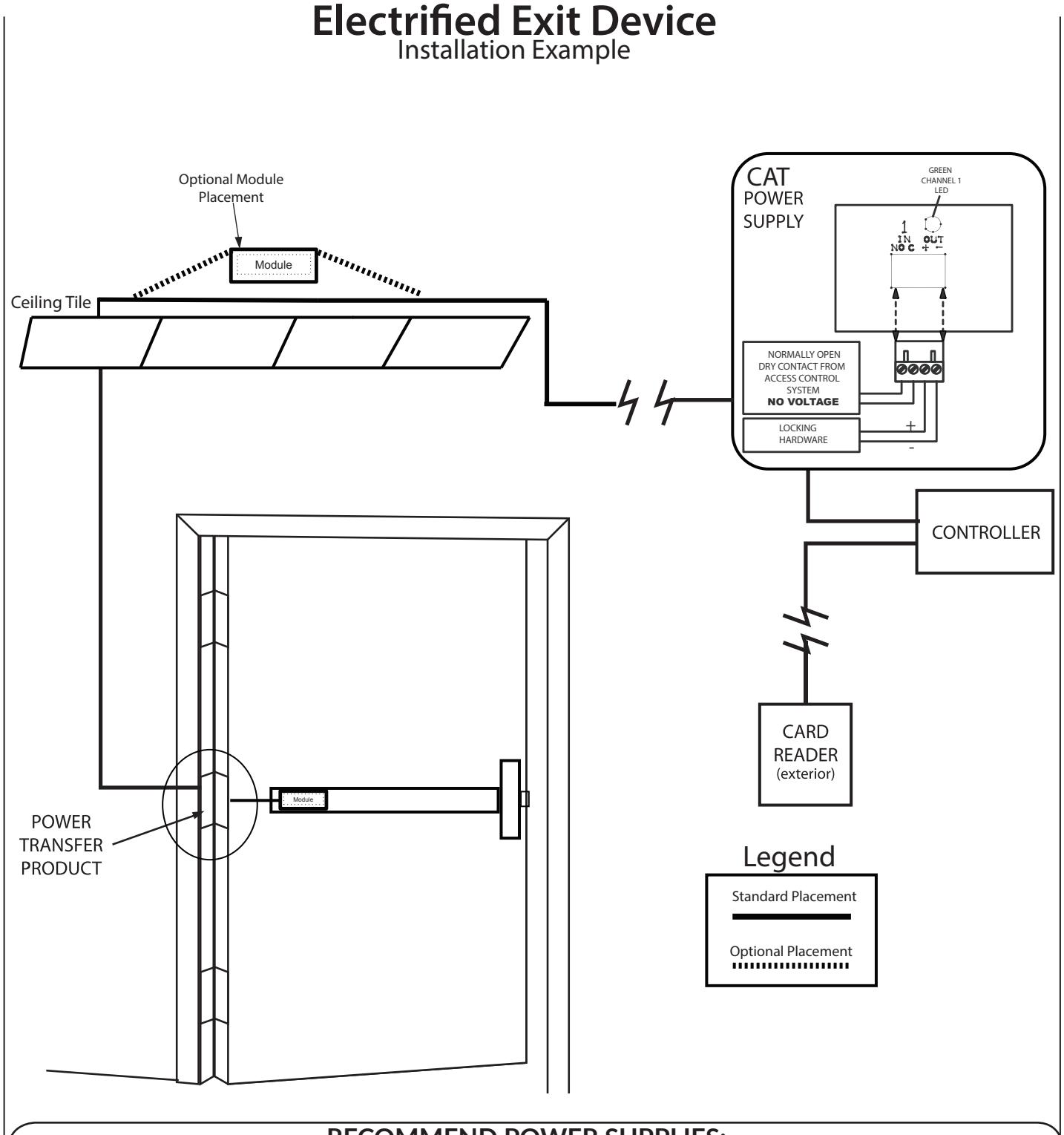
All Command Access exit devices & field installable kits have been thoroughly cycle tested with Command Access power supplies at our factory.
• PS210
- PS440B
- PS1
• PS5-4
- PS220/220B
- PS480B
- PS2/2B
- PS5-6
For more information click here or go to our website

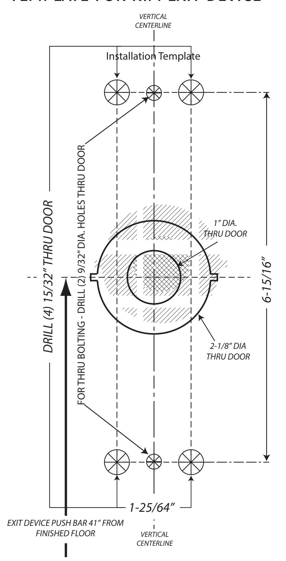
Template for rim exit device

BEFORE INSTALLING DEVICE, PLEASE CHECK:
- 1. IF DOOR FITTED AND HUNG.
- 2. SIZE OF EXIT DEVICE, FUNCTION AND DESIGN...
2.1. 36"DOORS, CAN BE CUT TO FIT DOORS DOWN TO 30" WIDE. 2.2. 48"DOORS, CAN BE CUT TO FIT DOORS DOWN TO 36" WIDE.
2.3. HAND OF DEVICE AGAINST APPLICATION.
1.PREPARE DOOR
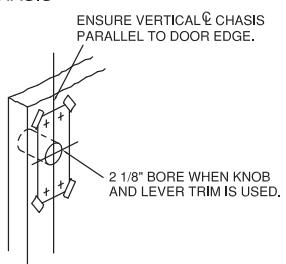
1.1 FOR 2 1/8" BORE PREP. POSITION TEMPLATE OVER EXISTING HOLE AND MARK FOR TWO CHASIS MOUNTING SCREW HOLES.
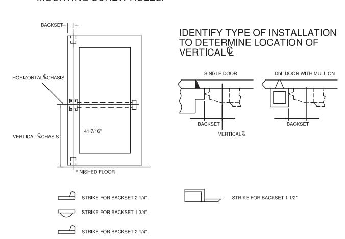
1.2 FOR DOOR W/O BORE PREP,MARK VERTICAL € CHASIS AND HORIZONTAL<sup>®</sup> CHASIS USING DIMENSIONS BELOW. MOUNTING SCREW HOLES.
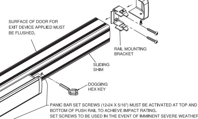
END CAP
BOTTOM OF PUSH RAIL TO ACHIEVE IMPACT RATING. SET SCREWS TO BE USED IN THE EVENT OF IMMINENT SEVERE WEATHER
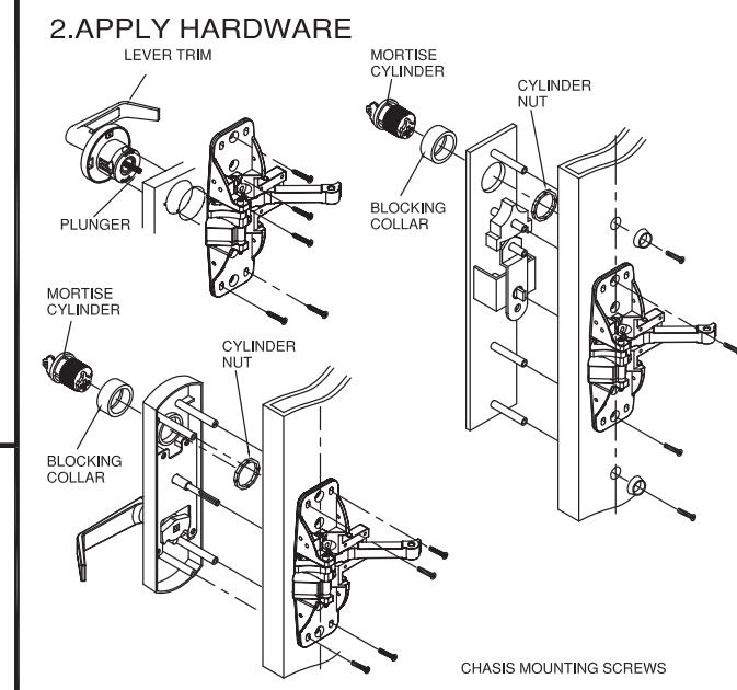
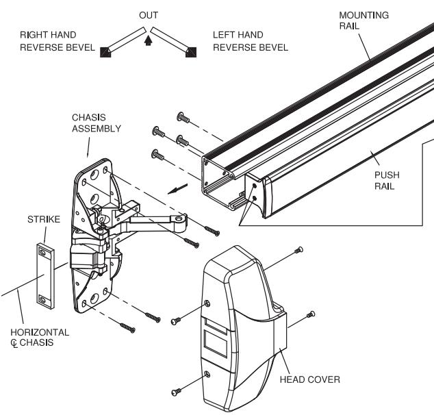
3. APPLY RAIL ASSEMBLE
- 3.1 CHECK THE SIZE OF DEVICE, IF CUTTING TO LENGTH IS REQUIRED.
- 3.2 DETERMINE CUT OFF LENGTH "X" BY SUBTRACTING 1-3/4" FROM "Y". MARK CUT OFF POINT ON MOUNTING RAIL.
- 3.3 DEPRESS ARM INTO RAIL OPENING AND SLIDE RAIL ONTO CHASIS. LEVEL RAIL AND FASTEN CHASIS AND MOUNTING PLATE.
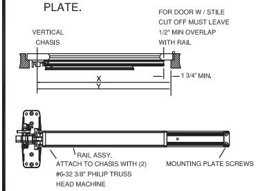
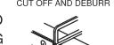
DON'T CUT CLOSER THAN 1-3/4" FROM LOWER PIUOT.
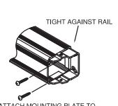
ATTACH MOUNTING PLATE TO DOOR WITH (3) ROUND HEAD SCREWS.
4. APPLY COVER AND STRIKES
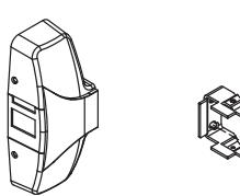
SCREW.
ATTACH COVER TO CHASIS WITH ATTACH END CAP TO MOUNTING (4) #8 TRUSS HEAD MACHINE PLATE WITH (2) COVER SCREWS.
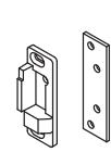
ATTACH STRIKE TO DOOR STOR WITH (2), STRIKE SCREW AND LOCK