OBDE Installation Instructions i-ea00156-rev1
Open the original PDF document
View PDF

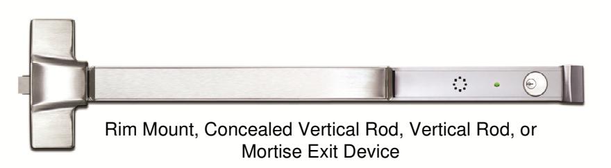
4501 On-Board Delayed Egress Exit Device
PUSH UNTIL ALARM SOUNDS. DOOR CAN BE OPENED IN 15 SECONDS.
When unauthorized egress is initiated by depressing the push pad of the 4501 OBDE, an audible alarm will sound and an irreversible unlock delay period of 15 seconds will begin. Meanwhile, the person exiting must wait to egress, allowing personnel or security time to respond to the alarm. After the delay period has expired, the device unlocks, permitting egress until the device is reset. In a life safety emergency, the device will immediately unlock upon loss of power or when powered by a fire control supervised power supply. The included signage provides clear and comprehensive instructions of the door egress operation for persons without prior knowledge of the exit delay, including the sight and hearing impaired.
4501 OBDE Applications include:
- Restricting the egress of wandering patients for their own safety.
- Restricting the egress of commercial center patrons for security application needs.
- Controlling pedestrian traffic in transportation facilities, including airport jetways and tarmacs
- Reducing shoplifting and employee theft
Standard Features:
Egress Delay
- 15 second exit delay
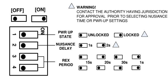
- 1 or 2 second nuisance delay
- Optional 30 second delay with AHJ approval
Built-In Visual & Audible Annunciation
- Armed mode
- Nuisance mode
- Irreversible egress mode
- Release mode
Trigger Modes
Rev 1, Rev Date: 9/28/19
- Egress alarm triggered by Push Bar
- Trigger input from external device (Pair of Doors)
- Door opened in secure mode (Door Forced or Prop)
Control Inputs
- Field-selectable 1 to 30 second request-to-exit with anti-tailgate and door prop alarm.
- Bypass
- Reset
- Remote trigger (for Pairs of Doors)
- DPS (Required for Door Forced, Prop and Anti-Tailgate)
Monitoring Outputs
- Secure/Unsecure status
- Egress initiation status
- Released/Bypass status
Recommended Accessories
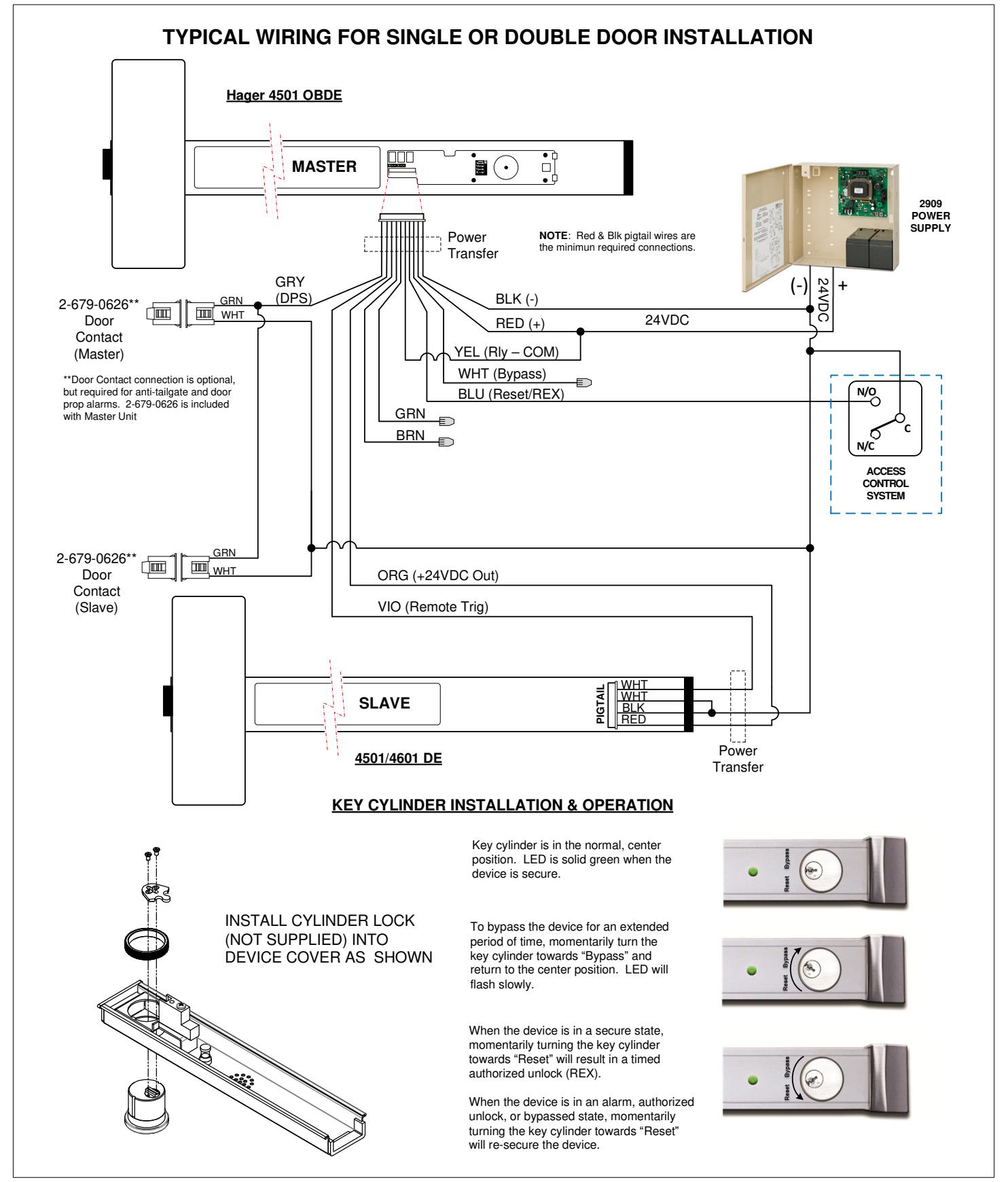
- 4501 DE Delayed Egress Slave Exit Device (for Pair of Doors)
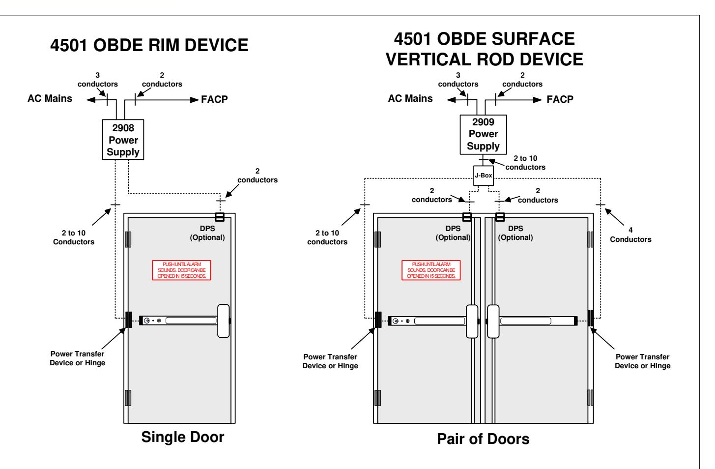
- 2900 Series regulated & filtered power supply 2908 (1 Amp) or 2909 (2 Amp)
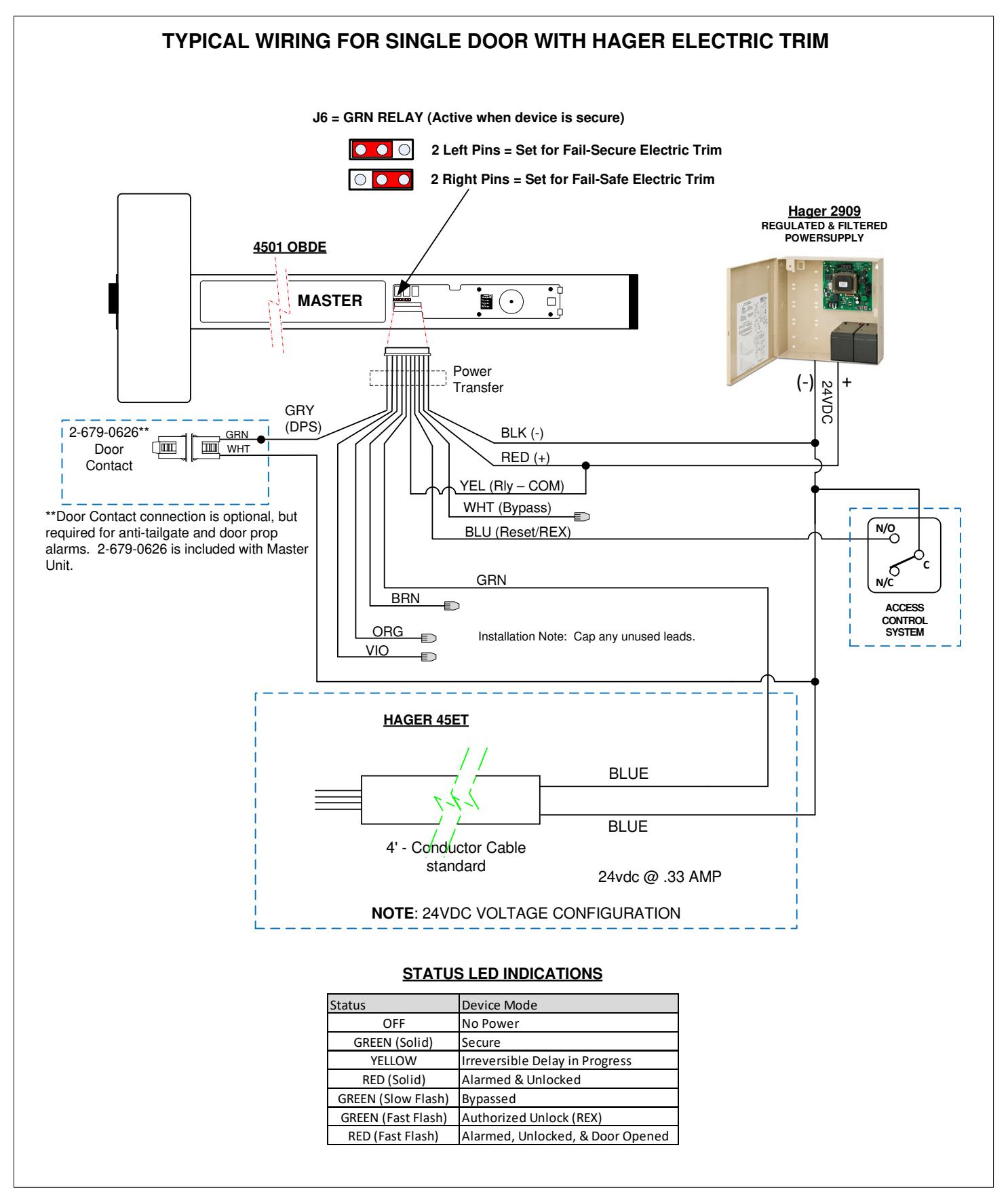
- Door contact (included) 2-679-0626 magnetic switch
- Power Transfer Device ETW/ETM/EPT
Code Compliance
- IFC International fire Code
- IBC International Building Code
- NFPA 101 Life Safety Code
- NFPA 1 Uniform Fire Code
- California Building Code with the exception of Sec. 11B-309.4 2013 edition.
- Field selectable automatic or manual power up after emergency release or power loss. Use of manual power up complies with California Building Code (OSHPD) requirements.
SECURITY


<u>4501 OBDE – Operational Description</u>
The door is normally closed and secured by the 4501 On-Board Delayed Egress Exit Device. The on-board status LED illuminates Green indicating that the unit is secured. The integral Reset/Bypass key switch is in the center position.
Activation/Alarmed Release: Pressing the push pad of the 4501 OBDE device initiates the irreversible 15 second unlock delay cycle. To prevent false alarms, a pre-alarm audible warning tone is activated during the short nuisance delay period. Releasing the push pad during the nuisance delay period will silence the pre-activation warning tone, reset the unlock delay cycle, and keep the door locked.
Once the nuisance delay period has been exceeded, the 4501 OBDE continues its irreversible door release cycle. An audible tone and Yellow status LED inform the person intending to exit of the door release cycle activation. An alarm output is activated to alert personnel of an unauthorized exit. After the delay cycle has expired, the status LED illuminates Red, and power is removed from the locking device, allowing free egress by pressing the push pad. A second output is activated indicating that the door is unsecure.
Reset/Relock (from an Alarm, REX, or Bypass state): The 4501 OBDE can be manually reset by authorized personnel by closing the door and turning the integral key switch to the reset position, or by momentarily activating a N/O switch connected to the remote Reset/REX control input.
Request-to-Exit (from a Secure state): A timed Request-to-Exit (REX) cycle is initiated by authorized personnel by momentarily turning the integral key switch to the reset position, or by momentarily activating a N/O switch connected to the remote Reset/REX control input. The power will be removed from the locking device allowing free egress by pressing the push pad. The on-board status LED will rapidly flash Green (2x / sec) during the REX cycle. After the REX cycle has expired, the 4501 OBDE will automatically re-apply power to the locking device to re-secure the door. If an external door position switch is connected to the DPS input, the door will automatically relock on door closure.
Authorized Maintained Bypass (from a Secure state): Unlocking the door for an extended period of time is accomplished by momentarily turning the integral key switch to the Bypass position, or by momentarily activating a N/O switch connected to the remote Bypass control input. The power will be removed from the locking device allowing free egress by pressing the push pad. The on-board status LED will slowly flash Green (1x / sec) during Bypass mode. The 4501 OBDE may be re-secured using the Reset procedure described above.
(NFPA-101)
The 4501 OBDE operation complies with the following building and fire codes: NFPA 101; NFPA 1-UFC; UBC; IBC; IFC; SBC; California Building Code. Listings: UL Listed: Special Locking Arrangements and Auxiliary Locks; California State Fire Marshal (CSFM) Listed.
| Option | Delay Release | Nusiance | Reset after | Lock Status on |
|---|---|---|---|---|
| Code | Time | Time | Alarm | Power-Up |
| ND |
15 sec
Fixed |
1 sec or 2 sec
Selectable |
Manual |
Locked or Unlocked
Selectable |
| NH | 30 sec | 1 sec or 2 sec | Manual | Locked or Unlocked |
| (AHJ Approval) | Fixed | Selectable | Selectable | |
| NC | 15 sec | 1 sec or 2 sec | Manual | Unlocked |
| (CBC Compliant) | Fixed | Selectable | Fixed |
Per BOCA compliance, the 4501 OBDE is manually reset by authorized personnel after an alarm by closing the door and turning the integral key switch to the reset position, or by momentarily closing a contact connected to the remote Reset/Bypass control inputs. In addition, a reset will be automatically be initiated once the door has been opened, then closed, and remains closed for 30 consecutive seconds.
(BOCA/Chicago)
Rev 1, Rev Date: 9/28/19
The 4501 OBDE operation complies with BOCA National Building Code and the Chicago Building Code: UL Listed, Special Locking Arrangements and Auxiliary Locks.
|
Option
Code |
Delay Release
Time |
Nusiance
Time |
Reset after
Alarm |
Lock Status on
Power-Up |
|
|---|---|---|---|---|---|
| ; | BD |
15 sec
Fixed |
1 sec or 2 sec
Selectable |
Auto/Manual |
Locked or Unlocked
Selectable |
|
BH
(AHJ Approval) |
30 sec
Fixed |
1 sec or 2 sec
Selectable |
Auto/Manual |
Locked or Unlocked
Selectable |
|
| ВС |
15 sec
Fixed |
0 sec
Fixed |
Auto/Manual |
Locked or Unlocked
Selectable |

4501 OBDE Board Layout (LR Device shown)

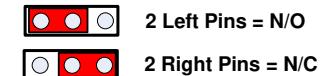
MONITOR RELAY JUMPER SETTINGS*
*Individually sets the polarity of the GRN & RED relays when the relay is in an ACTIVE state.
Rev 1, Rev Date: 9/28/19
J6 = GRN RELAY (Active when device is secure) J7 = RED RELAY (Active upon alarm intiation)
DIP SWITCH SETTINGS

Rev 1, Rev Date: 9/28/19
4501 On-Board Delayed Egress Installation Instructions I-EA00156
Device Wiring Pigtail
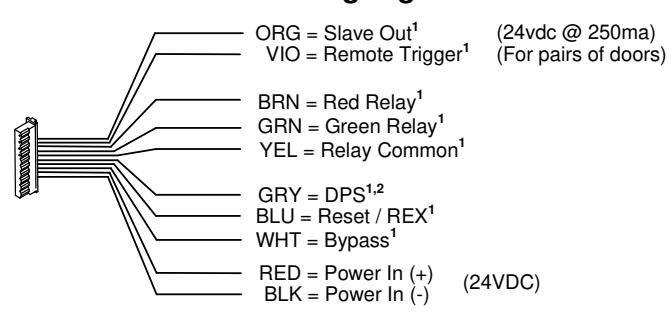
1 THESE WIRES SHALL BE CONNECTED TO AN ACCESSORY IN THE PROTECTED AREA. UNUSED WIRES SHOULD BE CAPPED OFF.
A DOOR CONTACT IS REQUIRED FOR ANTI-TAILGATE AND DOOR PROP FUNCTIONS.
Electrical Specifications:
Input Voltage : 24VDC +/- 10% Input Current : 540ma Max
Monitor Relays: 1 Amp contacts @12/24vdc
Slave Output: 24VDC @250ma
Enviromental:
Max Operating Temperature: C to C Tested to 85% RH @30°C
| Wire Color | Wire Designation | Description |
|---|---|---|
| Used for a pair of doors (master & slave). This is a voltage output (24VDC @250mA). | ||
| Connect this wire to +24VDC (Red wire) of the slave bar. | ||
| Orange | Slave Out | See "Typical Wiring for Double Door Installation". |
| Used for a pair of doors (master & slave). This is a dry input. Connect this wire to one leg of the Slave Trigger output. The other leg of the Slave Trigger output is connected to ground (-VDC). Closing the switch shorts this wire to ground and | ||
| initiates the alarm sequence. | ||
| \ , c | See "Typical Wiring for Double Door Installation". The two white wires on the | |
| Violet | Remote Trigger | slave bar are the Normally Open trigger switch. |
| Brown | Red Relay | This is the Alarm Relay Output (Dry, 1A@12/24VDC). It is normally INACTIVE when the door is secure. It changes state when the bar is pressed beyond the nuisance delay and placed into an Alarm state. It may be configured as Normally Open OR Normally Closed using Jumper J7. The YELLOW wire is the relay common. |
| This is the Door Secure Relay Output (Dry, 1A@12/24VDC). It is normally ACTIVE when the door is secure. It changes state when the bar unlocks after (a) the delayed egress countdown expires, (b) an authorized Request-to-Exit(REX) signal, or (c) the bar is Bypassed. It may be configured as Normally Open OR Normally | ||
| Green | Green Relay | Closed using Jumper J6. The YELLOW wire is the relay common. |
| Yellow | Relay Common | This is the shared relay common for both the Red & Green Relay. |
| Grey | Door Position Switch (DPS) | This is a dry input. Connect this wire to one leg of a Door Contact switch. The other leg of the Door Contact switch is connected to ground (-VDC). The Door Contact polarity must be OPEN when the door is closed. A door contact is required for antitailgate and door prop alarm functions. |
| Grey | Door Fosition Switch (DFS) | This is a momentary, dry input. Connect this wire to one leg of a Normally Open |
| switch. The other leg of the Normally Open switch is connected to ground (-VDC). When the bar is in a secure state, shorting this input will result in an authorized unlock (REX). The REX period is configured by the dip switch settings. When the bar is in an alarm, authorized unlock state, or in a bypassed state, | ||
| Blue | Reset/REX | shorting this input will reset (secure) the bar. |
| This is a momentary, dry input. Connect this wire to one leg of a Normally Open switch. The other leg of the Normally Open switch is connected to ground (-VDC). When the bar is in a secure state, shorting this input will unlock the device | ||
| White | Bypass | indefinitely, until the bar is Reset. |
| Red | Power IN (+) 24VDC | Input Voltage: 24VDC +/- 10%; Input Current: 540mA (max). The Red & Black wires |
| Black | Power IN (-) 24VDC | are the minimum required connections. |

Rev 1, Rev Date: 9/28/19


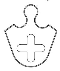
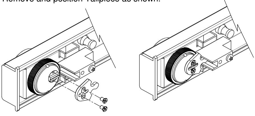
Use Hager 3978 Clover Tailpiece or equivalent.
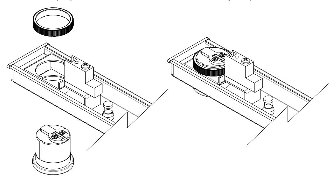
1 Install Key Cylinder as shown and secure with locking nut provided.
2 Remove and position Tailpiece as shown.
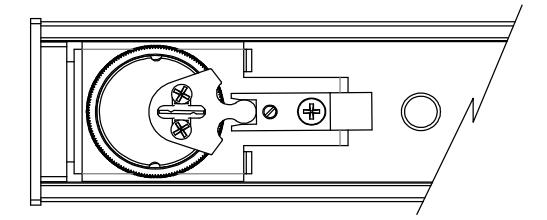
3 Insert Key and check for proper operation.