Norton Rixson Electrified Closers and Holders Catalog_43509
Open the original PDF document
View PDF
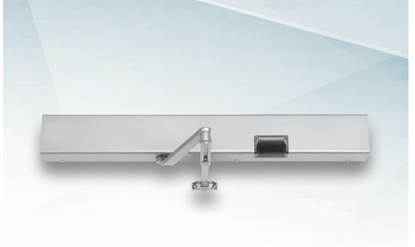
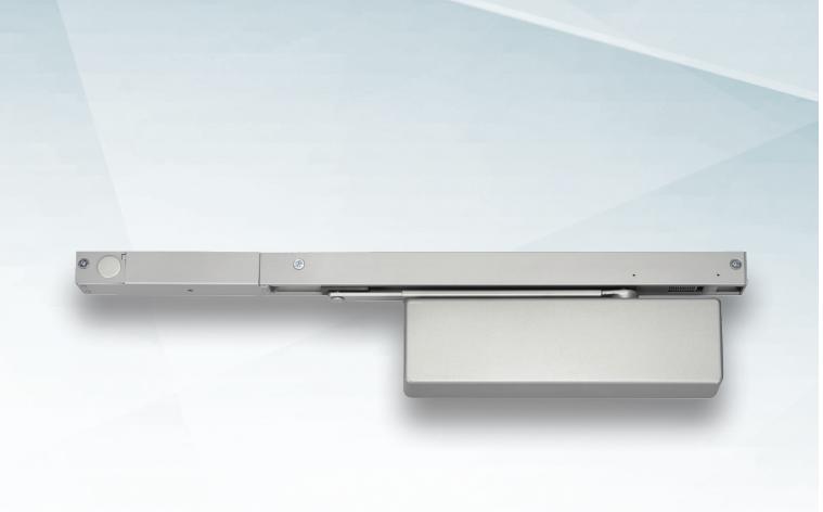
TABLE OF CONTENTS
ELECTRIFIED CLOSERS AND HOLDERS
| 710052 | |
|---|---|
| Introduction, Features, Benefits, Certifications, Patents | |
| Specifications | |
| 7110SZ, 7150SZ | |
| 7120SZ, 7130SZ | |
| Parts List | |
| How To Order | 8 |
| 7200 | |
| Introduction, Features, Benefits | |
| Overview, Certifications, Specifications | 1C |
| Explanation of Features | |
| 7210MPSO, 7210RFS, 7250MPSO | 12 |
| 7220MPSO, 7220RF, 7230MPSO, 7230RFS | 13 |
| 7240 | 14 |
| 7290 | 15 |
| Parts List | 16 |
| How To Order | 17 |
| 7700PT | |
| Introduction, Features, Benefits, Overview, Certifications | 18 |
| Explanation of Features, Voltage Info. | |
| 7705PTO | |
| P7705PTO | |
| Electrical Info., Specifications | 22 |
| Parts List | |
| How To Order | 25 |
| Smok-Chek® V, Checkmate® 99 | |
| Introduction, General Info, Specifications | 26 |
| Smok-Chek V | |
| 0600, 0601 | 27 |
| 0602, 0100 | |
| 0101 | |
| How To Order, Product Comparison Chart | |
| Parts List | |
| Checkmate 99 | |
| 99-726, 99-926 | 77 |
| How To Order | |
| Parts List | |
7100S7 SAFF7ONF®

INTRODUCTION
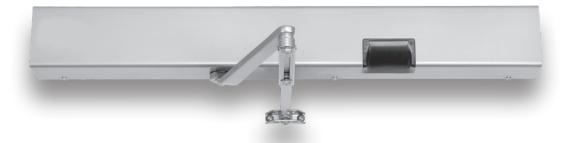
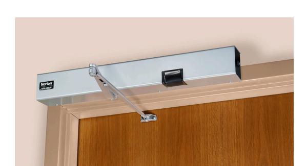
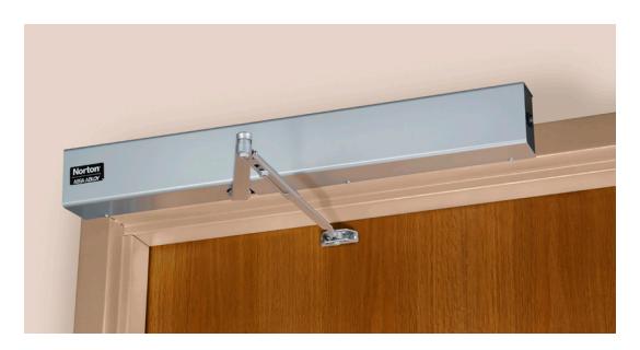
The 7100 Series SafeZone® door closer safeguards occupants throughout a variety of facilities with the detection of movement through doorways and intelligent door control functions. A multipoint electromechanical closer with a programmable motion sensor allows the door to open manually and remain open when one or more people travel through the opening.
FEATURES
- Multi-point, electromechanical closer/holder
- Sensor detects movement in both directions
- Selectable hold open time and sensitivity
- Push or pull side mounting
- Handed units
- Spring sizes 3. 4 or 5 (models 7110SZ and 7150SZ): Spring sizes 2, 3, 4 or 5 (models 7120SZ and 7130SZ)
- Fail safe operation
- Optional dual sensor
- 2-year limited warranty
BENEFITS
- Energy savings realized by power engaging only when motion is detected
- Extends door life and minimizes wear and tear on hardware by limiting unnecessary cycles
CERTIFICATIONS
- CAL FIRE, 3550-0944:0112
- Models 7122SZ, 7132SZ, 7113SZ and 7153SZ meet requirements for Americans with Disabilities Act (ADA) and ANSI A117.1


- UL10C positive pressure up to 3 hours (1)
- UL-cUL listed
- Manufactured in an ISO 9001. ISO14001 facility
PATENTS
assaabloydss.com/patents
ELECTRIFIED CLOSERS AND HOLDERS
SPECIFICATIONS
Manufacturer: Door closers for both interior and exterior openings are to be the product of a single source manufacturer.
Electromechanical closer units to be a multipoint, closer/holder type with selective hold open positioning achieved by electronic solenoid locking of closer arm slide into the track assembly. Closer/holder units to have a maximum opening of 180° (hold open to 175°) and are fail safe to close the door in the event of electrical power interruption.
SafeZone Detection: Closer/holders units to have an integral sensor device monitoring a "zone of safety" at the door opening. SafeZone detection prevents the door from closing in the event of movement within the adjustable sensing field. Movement is detectable in both directions with selectable closer hold open time and sensor sensitivity.
Mechanical closer to be hydraulic type with full rack and pinion construction enclosed in a cast aluminum alloy shell. Internal hydraulic fluid is to be nongumming and non-freezing. Include two non-critical valves to independently regulate sweep and latching speeds and an adjustable backcheck cushioning valve. All valves are adjustable by hex key. Provide spring power adjustment permitting a 50% increase in closing power over the minimum closing force for any closer size
Mounting: Closer units can be surface mounted to the frame face for application on the pull (hinge side) side of door, or soffit mounted on the push side of the door frame with projection of no more than 2-5/8" (67mm) from the frame face. Frame face must be a minimum 2" and ceiling clearance a minimum of 4". Door must be hung on either butt hinges or 3/4" offset pivot hinges, minimum 1-3/4" to 2-1/4" thickness.
Installation: Provide optional handheld remote device for programming SafeZone sensor settings. Auxiliary door stops are recommended at closer/holder openings and required at doors opening beyond 110°. Interior installation only.
Power: Closer units operate on (120VAC, 60Hz) or (24VDC) with an amperage draw not exceeding (.086 Amps for 24VDC) (.051 Amps for 120VAC). Supplier to coordinate electrical requirements with electrical and alarm system engineers. Field wiring (and conduit) by others.
Electromechanical SafeZone Closer/Holder to be Norton Rixson 7100SZ Series.
ELECTRIFIED CLOSERS AND HOLDERS
7110SZ Shown
PULL SIDE
- Surface mounted to the pull (hinge) side frame face
- Slide track mounts directly to door
- Minimum 4" ceiling clearance required
- 1/8" (3mm) maximum frame reveal
- Handed
- Standard units accommodate doors opening 180°; maximum 175° hold open (110° maximum for 7150SZ series).
- Buffer block assembly in the track will accommodate doors opening to 125°
- Auxiliary door stop is required for doors opening beyond 125°
- Fail Safe solenoid will de-energize in the event of power failure
- Accommodates either concealed or surface wiring
-
Selective hold open
- Standard on all units (can be disengaged)
- Activates the viewing sensor only when the door opens beyond a specific angle
- Once the door is manually opened past the set point, SafeZone holds the door until movement is no longer detected
- If the door is not opened to the predetermined opening angle, SafeZone operates like a regular door closer and simply closes the door
- NorGlide® closer fluid
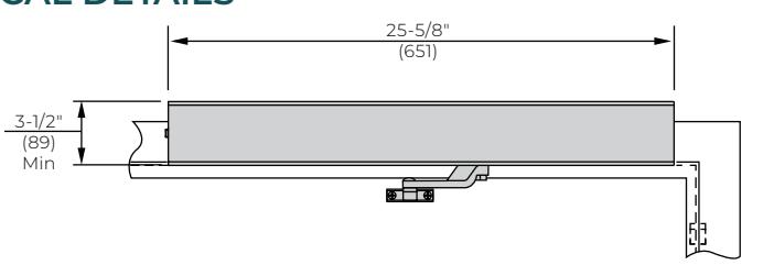
TECHNICAL DETAILS
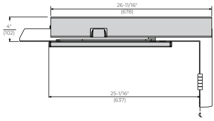
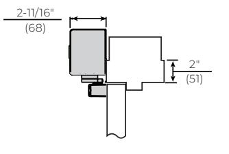
Minimum door width = 28" (71cm) Deep reveals
- Special slide arm is available for reveals in excess of 1/8" (3mm) up to 3" (76mm) 7150SZ Series
- 110° maximum door swing
DOOR SIZE
|
Maximum
Door Size (cm) |
Model
Number |
Model Number –
Deep Reveal |
|---|---|---|
| 40" (102) | 7113SZ | 7153SZ |
| 44" (112) | 7114SZ | 7154SZ |
| 48" (122) | 7115SZ | 7155SZ |
ELECTRICAL DATA
| Series Operating | No. Power | Amperage Draw | |
|---|---|---|---|
| Number | Voltage (Input) |
Input Lines*
(Pairs) |
Solenoid Coil |
| 7110SZ | 24VDC | 7 | .070 @ 24VDC |
| 7150SZ | 120VAC | I | .035 @ 120VAC |
* Max/min operating voltage parameters +10% / -15%.
ELECTRIFIED CLOSERS AND HOLDERS
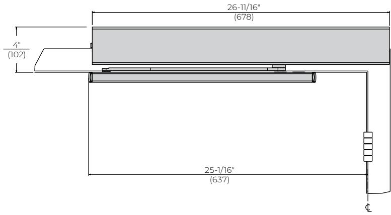
PUSH SIDE
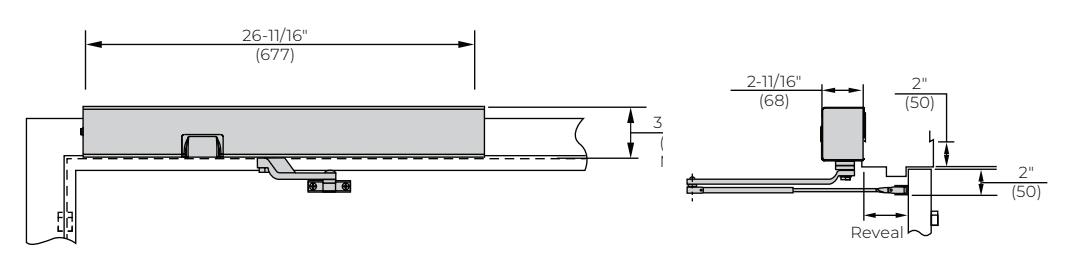
- Surface mounted to the push (stop) frame face
- Double lever arm mounts directly to the door
- Minimum 4" (102mm) ceiling clearance required
- Handed
- Standard units accommodate doors opening 180°; maximum 175° hold open
- Fail safe solenoid will de-energize in the event of power failure
- Accommodates either concealed or surface wiring
-
Selective hold open
- Standard on all units (can be disengaged)
- Activates the viewing sensor only when the door opens beyond a specific angle
- Once the door is manually opened past the set point, SafeZone holds the door until movement is no longer detected
- If the door is not opened to the predetermined opening angle, SafeZone operates like a regular door closer and simply closes the door
- NorGlide® closer fluid
TECHNICAL DETAILS
Note: for applications with narrow top rails or limited ceiling clearance, a special drop angle bracket is required. See page 7.
DOOR SIZE
|
Maximum
Door Size (cm) |
Model
Number |
Maximum
Degree of Opening |
Reveal Range
(Inches/mm) |
|
|---|---|---|---|---|
| 180° | 2-3/4" - 4" (70-102) | |||
| ADA | 7122SZ | 165° | (|| E|| (100 1E0) | |
| 7132SZ | 180° | 4"-7" (102-178) | ||
| F10767 | 180° | 2-3/4" - 4" (70-102) | ||
| 40" (102) | 7123SZ | 165° | (II EII (200 2E0) | |
| 7133SZ | 180° | 4"-7" (102-178) | ||
| F10 / 67 | 180° | 2-3/4" - 4" (70-102) | ||
| 44" (112) | 7124SZ | 165° | (|| F|| /100 1F0) | |
| 7134SZ | 180° | 4"-7" (102-178) | ||
| F10F67 | 180° | 2-3/4" - 4" (70-102) | ||
| 48" (122) | 7125SZ | 165° | (|| || || || || || || || || || || || || | |
| 7135SZ | 180° | 4"-7" (102-178) | ||
ELECTRICAL DATA
|
Series
Number |
Operating
Voltage |
No. Power
Input Lines* |
Amperage
Draw |
|---|---|---|---|
| Number | (Input) | (Pairs) | Solenoid Coil |
| 7110SZ | 24VDC | ٦ | .070 @ 24VDC |
| 7150SZ | 120VAC | l | .035 @ 120VAC |
* Max/min operating voltage parameters +10% / -15%.

CLOSER BODIES
| Description | Mounting | Hand | Part Number |
|---|---|---|---|
| Left | 720XLAP24L | ||
| Closer bodies | Push or pull | Right | 720XLAP24R |
ARM & TRACK ASSEMBLIES
| Description | For Series | Part Number |
|---|---|---|
| Slide track | 7110SZ, 7150SZ | 7100-1T |
| Slide arm | 7110SZ | 7110-1A |
| Double lever arm | 7120SZ | 7701-1A |
| Double lever arm | 7130SZ | 7701-1B |
| Double egress arm - left hand | F15067 | 7150-1L |
| Double egress arm - right hand | 7150SZ | 7150-1R |
TRACK & ARM PARTS
| Description | Part Number | |
|---|---|---|
| Slider assembly | 2800SLD | |
| Cushion block | 7100CB | |
COVERS
| Description | Part Number |
|---|---|
| Left hand (for LH pull OR RH push units) | 7100CL |
| Right hand (for RH pull OR LH push units) | 7100CR |
MISCELLANEOUS PARTS
| Description | Part Number |
|---|---|
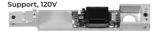
| Power supply (120V only) | 7100PS |
| Remote | 7100REM |
| Selective hold open switch assembly 24V | SHOK |
| Sensor kit | 7100SK |
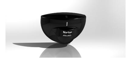
7100SK
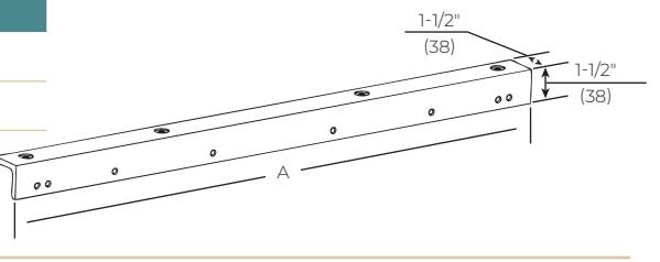
| Description | Part Number | A (Length) |
|---|---|---|
| Drop angle bracket | 7100DAB | 29-9/16" (675) |
| 7100DAB-180 | 24-9/16" (621) |
ELECTRIFIED CLOSERS AND HOLDERS
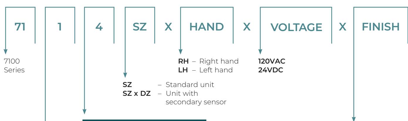
HOW TO ORDER
Note: All transmitters (door switches or key fob) must be ordered separately.
| Closer Size | ||
|---|---|---|
|
Maximum
Door Size |
||
| ADA | ||
| 44" | ||
| 48" | ||
| Maximum | ||
| Door Size | ||
| Door Size | ||
|
Door Size
ADA |
||
Specifies side of door unit is mounted on and the type of arm
Pull Side
"1" – Rigid slide arm & track; maximum reveal 1/8" (3mm) "5" – Double egress slide arm & trac
Double egress slide arm & track; reveals 1/8"-3" (3-76mm) to 110°
Push Side
"2" – Double lever arm; reveals 2-3/4"-4" (70-120mm) to 180°, reveals 4"-7" (102-179mm) to 165°
"3" – Double lever arm; reveals 4"-7" (102-179mm) to 180°
FINISHES
Product will be sprayed with a combination of waterborne acrylic and polyester powder coat.
| ANSI/BHMA (US) | Description |
|---|---|
| 613E (US10BE) | Dark oxidized satin bronze - equiv. |
| 689 (US28) | Aluminum, painted |
| 690 (US20) | Dark bronze, painted |
| 691 (US10) | Light bronze, painted |
| 693 | Black, painted |
| 694 | Medium bronze, painted |
| 696 (US4) | Gold , painted |
| BSP | Black suede powder coat |
| WSP | White suede powder coat |

INTRODUCTION
The 7200 Series Electromechanical Closer/Holders combine the functions of an electromechanical door holder with the 7700 series door closer.
The 7200MPSO (support units) consists of an on-board power supply (for 120VAC input option) or a terminal strip (for 24VDC input option) and a door closer assembly with internal electrohydraulic holder capability. This unit (120VAC or 24VDC) is intended to control a single door or a pair of doors where the building's alarm system monitors the power to the Support Unit (24VDC input.).
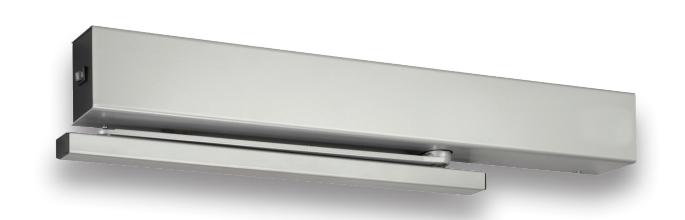
Executive™ units (RFS suffix) consists of an on-board power supply (for 120VAC input option) or a terminal strip (for 24VDC input option), a 433MHz radio frequency receiver and a door closer assembly with internal electro-hydraulic holder capability. Unit is intended to provide remote wireless release of a door that has been manually placed into the electrified hold open position. Not intended for use in life safety applications.
FEATURES
- Multi-point hold open
- Fixed spring sizes 3, 4, or 5
- Push or pull side mounting (frame mounted)
- Adjustable sweep and latch speed valves
- Handed
- Adjustable backcheck cushioning and position valve
- Selective hold open (SHO) allows door to hold open at any degree of opening beyond a pre-set hold open point, up to 175°
- Metal covers
- Fail safe: solenoid will de-energize in the event of power failure
- Concealed or surface wiring
- Minimum 4" ceiling required
- Auxiliary door stop is required for doors opening beyond 125° (pull side mounting)
- NorGlide® closer fluid
- 2-year limited warranty
BENEFITS
- Adjustable hold open position allows application flexibility
- Connected free swing arm option allows door to be held open at any degree
- Doors automatically close if activated by fire alarm
ELECTRIFIED CLOSERS AND HOLDERS
OVERVIEW
CERTIFICATIONS
- UL10C positive pressure up to 3 hours (1)
- UL-cUL listed
- Manufactured in an ISO 9001, ISO 14001 facility
- Environmental Product Declaration (EPD)
SPECIFICATIONS
Closer for _____ doors shall be electromechanical and completely enclosed in a metal cover. Units shall be surface mounted to the frame face [on the pull (hinge side) or the push (opposite hinge side)] of the door [and shall project no more than 2-11/16" (68mm) from the surface of the frame]. (Closer shall be installed in the header of the frame, and the slide track mortised into the door's top rail). Closer unit shall be hydraulic, full rack and pinion type with a cast aluminum alloy shell. Hydraulic fluid shall be non-gumming and nonfreezing. Closer unit shall have two noncritical valves to independently regulate closing and latch speed. It shall also have an adjustable backcheck with a hex-key. Closer unit shall have spring power adjustment to permit a 50% increase in closing power over the minimum closing force for any size. Electromechanical Closer shall have (Infinite) (Selective) Hold Open (Free Swing Operation) and shall be able to attain a maximum opening of 180° (with hold open to 175°). Unit to be fail safe and must close the door during any electrical power interruption to the unit. (Closer/Holder to be Executive Door Holder/ Release with release actuated by battery operated handheld controller). Unit(s) to operate on (120VAC, 60Hz) (24VDC) and will accept (surface) (concealed) wiring. Amperage draw shall not exceed (.105 Amps for 24VDC) (0.46 Amps for 115VAC) units. Supplier to coordinate electrical requirements with electrical and alarm system engineers. Wiring (and conduit) by others.
Electromechanical Units to be Norton Rixson Series 7200 (Closer/Holder), (Free Swing Releasing Device), (Executive Door Holder/Release).

EXPLANATION OF FEATURES
Aluminum Alloy Housing
Closer bodies are constructed of a special aluminum alloy, carefully selected to accommodate interactive steel components and operating conditions
Rack & Pinion Operation
Provides a smooth constant control of the door through its full opening and closing cycle.
Spring Sizes
Specify closer size 3, 4 or 5. Size 6 available with 7290 overhead concealed units.
Sweep Speed Control Valve
Allows adjustment of door speed from the door's full open position down to approximately 10° from the closed position.
Latch Speed Control Valve
Allows adjustment of door speed from approximately 10° down to the door's fully closed position.
Adjustable Backcheck Cushioning
Provides control of the door in the opening cycle, beginning at approximately 75° of door opening. It slows/cushions the door opening, when the door is forcibly opened beyond its pre-adjusted limits.
Closer Fluid
NorGlide® closer fluid is a specially formulated multi-viscosity hydraulic fluid that contains lubricity and anti-oxidation agents that provide optimum performance and efficiency. This fluid complements the interaction of the door closer's aluminum housing with its steel and brass components, while maintaining stable viscosity to allow the door closer to perform in temperatures ranging from extremely high to as low as -40° F.
Adjustable Backcheck Position Valve
Allows the door opening position, where backcheck cushioning begins, to be adjusted to a greater door angle, up to a maximum of 20° farther (approximately 95°).
Handed
Specify right or left hand when ordering.
Selective Hold Open (standard)
The door will hold open at any degree of opening beyond a pre-set hold open point, up to 175°, with a maximum allowable door opening of 180° (exception series 7250 at 110°).
Infinite Hold Open
The door will hold open at any degree of opening up to 175°, with a maximum allowable door opening of 180° (exception series 7250 at 110°). Can be set in the field by turning cam.
Fail Safe
In the event of a power failure, the solenoid will de-energize and the closer/holder will then operate as a normal door closer
Wiring Option
All 7200 series electromechanical closer/holders will accommodate either concealed or surface wiring.
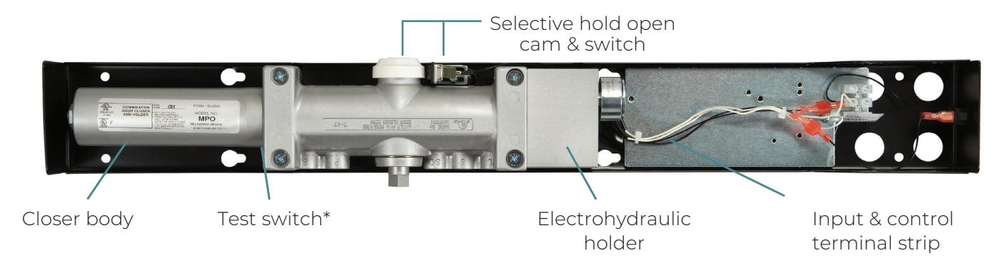
Selective Hold Open Switch and Cam:
The selective hold open starting point is determined by a switch and adjustment cam assembly. The cam is attached to the upper pinion shaft by means of a machine screw. As the door is opened, the pinion shaft will rotate the cam and operate the switch to the "on" position to initiate hold open. When the door is closed, the pinion cam will operate the switch to the "off" position. The cam is factory set to operate at 80° of door opening. The cam can be easily field adjusted to operate at virtually any degree of door opening.
Warranty
2-year limited warranty
7210MPSO Shown
ELECTRIFIED CLOSERS AND HOLDERS
SUPPORT UNITS
7210/7250
- Surface mounted to the pull (hinge) side frame face
- · Slide track mounts directly to door
- · Minimum 4" ceiling clearance required
- 1/8" (3mm) standard frame. For deeper reveals, a special slide arm is required (see chart below)
- Handed
- Standard units accommodate doors opening 180°; maximum 175° hold open
- Buffer block assembly in the track will accommodate doors opening to 125°
- Auxiliary door stop is required for doors opening beyond 125°
- Units shipped selective hold open; infinite hold open can be set in the field
- Fail safe solenoid will de-energize in the event of power failure
- Accommodates either concealed or surface wiring
Single Door:
• Executive™ Door Holder/Release: both series 7210RFS or 7250RFS are self-contained and can be installed to control a single door
TECHNICAL DETAILS
2-11/16" (68) 1 4" (102) 1 2" (51)
Note: Deep reveals
- Special slide arm is available for reveals in excess of 1/8" (3mm) up to 3" (76mm) 7250MPSO series
- 110° maximum door swing
DOOR SIZE
| Marianian | Model Number | ||
|---|---|---|---|
|
Maximum
Door Size (cm) |
Standard Reveal
(to 1/8" (3mm) reveal) |
Deep
Reveal (see note) |
|
| 40" (102) | 7213MPSO | 7213RFS | 7253MPSO |
| 44" (112) | 7214MPSO | 7214RFS | 7254MPSO |
| 48" (122) | 7215MPSO | 7215RFS | 7255MPSO |
* Max/min operating voltage parameters +10% / -15%

SUPPORT UNITS
7220/7230
- Surface mounted to the push (stop) frame face
- Double lever arm mounts directly to the door
- Minimum 4" (102mm) ceiling clearance required
- Handed
- Standard units accommodate doors opening 180°; maximum 175° hold open
- Units shipped selective hold open; infinite hold open can be set in the field
- Fail safe solenoid will de-energize in the event of power failure
- Accommodates either concealed or surface wiring
7220MPSO shown
TECHNICAL DETAILS
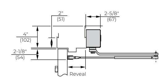
Note: for applications with narrow top rails or limited ceiling clearance, a special drop angle bracket is required. See page 16.
DOOR SIZE
|
Maximum
Door Size |
Model Number |
Maximum
Degree of Opening |
Reveal
Range (Inches/ mm) |
|
|---|---|---|---|---|
| 7223MPSO | 7223RFS | 180° |
2-3/4" - 4"
(70 - 102) |
|
| 42" (107) | 165° | 4" - 7" | ||
| 7233MPSO | 7233RFS | 180° | (102 - 178) | |
| 7224MPSO | 7224RFS | 180° |
2-3/4" - 4"
(70 - 102) |
|
|
48" (122)
7234MPSO |
165° | 4" - 7" | ||
| 7234RFS | 180° | (102-178) | ||
ELECTRIFIED CLOSERS AND HOLDERS
7240 CONNECTED FREE SWING ARM
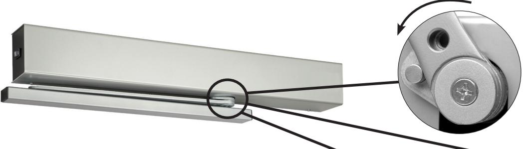
As the door is opened, the rigid slide arm rotates the arm driver and the pinion shaft of the closer mechanism.
When the door has
plunger valve will hold
degree of door opening. The door is then free to
door Close
the pinion shaft and
arm driver at that
swing unhindered.
been opened and released, the unit's electrically controlled
door free ★ swing
The connected free swing arm assembly provides the convenient automatic closing fire door protection for health care facilities or other locations where it is desired to neutralize the effort required to open or close a door. With no spring force on the door during the normal operation, patients, the handicapped and/or staff find the door easy to open, close or leave ajar.
Functions:
- Arm driver connected to the closer pinion drives the pinion when the door is opened and the slide arm rotates
- When unit is energized the pinion and arm driver remain at the point where door was initially opened
- Arm is connected to the pinion but is free to pivot
- The door is free to open, close or be set at any degree of opening
- When there is a fire/smoke alarm or any power interruption, the hold open control valve is released, and door closes
- Units shipped selective hold open; infinite hold open can be set in the field
UL Listed:
7200 Series with connected free swing arm is UL listed as a releasing device for fire/smoke barrier doors
| Model Numbers | |||
|---|---|---|---|
|
Maximum
Door Size (cm) |
Support |
Executive™ Door
Release |
|
| (====, | Selective I | Hold Open | |
| 40" (102) | 7243MPSO | 7243RFS | |
| 44" (112) | 7244MPSO | 7244RFS | |
| 48" (122) | 7245MPSO | 7245RFS | |
After fire/storm detection alarm or any bower interruption to
After fire/storm detection alarm or any power interruption to the control, the pinion shaft and arm driver are released to close the door.
Specify voltage and hand of door when ordering

7290 OVERHEAD CONCEALED SUPPORT UNIT
Controlled Remotely by Area/Ceiling Detectors
- Handed
- · Unit concealed in the header of the frame
- Installation requires a 4" (102mm) high frame header

- A 2" x 4" (51 x 102mm) dust/grout box and a removable frame stop (provided by the door and frame supplier) are required
- Slide track is mortised in the door's top rail
- Standard units accommodate doors opening 180°; maximum 175° hold open
- Buffer block assembly in the track will accommodate doors opening to 125°
- Auxiliary door stop is required for doors opening beyond 125°
- Units shipped selective hold open; infinite hold open can be set in the field
- Intended for use with compatible ul listed ceiling alarm detection equipment
- Fail safe solenoid will de-energize in the event of power failure
TECHNICAL DETAILS
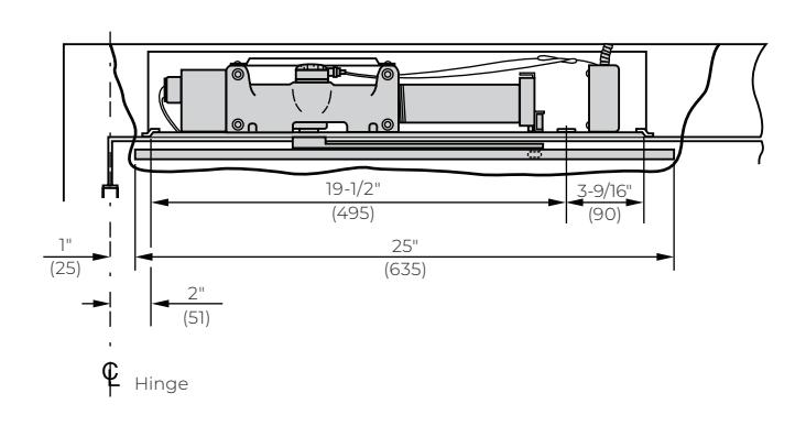
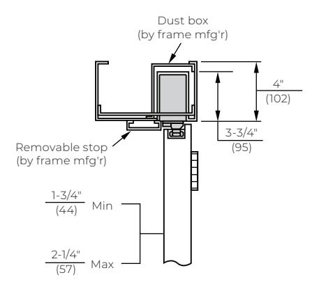
DOOR SIZE
|
Maximum Door Size
(cm) |
Selective Hold Open |
|---|---|
| 32" (81) | 7294MPS |
| 38" (97) | 7295MPS |
| 48" (122) | 7296MPS |
ELECTRIFIED CLOSERS AND HOLDERS
CLOSER BODIES
| Description | Mounting | Voltage | Hand | Part Number |
|---|---|---|---|---|
| Development II | 2.0.45.0 | Left | 720XLAPS24L | |
| Closer/holder assembly | Push or pull | 24VDC | Right | 720XLAPS24R |
ARM & TRACK ASSEMBLIES
| Description | For Series | Part Number |
|---|---|---|
| Slide track | 7210, 7240, 7250 | 7100-IT |
| Slide arm | 7210 | 7110-1A |
| Connected free swing arm | 7240 | 7140-1A |
| Double egress arm – right hand | 7150-1R | |
| Double egress arm – left hand | 7250 | 7150-1L |
| Double lever arm | 7220 | 7701-1A |
| Double lever arm | 7230 | 7701-1B |
| Arm assembly NHO – right hand | 7950-1R | |
| Arm assembly NHO – left hand | 7290 | 7950-1L |
| Track assembly NHO | 7950ST |
TRACK & ARM PARTS
| Description | Part Number |
|---|---|
| Cushion block (part of slide track assembly) | 7100CB |
| Screw pack for CFS arm | 7240SP |
| Slider assembly | 2800SLD |
MISCELLANEOUS PARTS
| Description | Part Number |
|---|---|
| Cover (support unit) | MPSOCOV |
| Selective hold open switch assembly 24V | SHOK |
| Switch 24V | SHO |
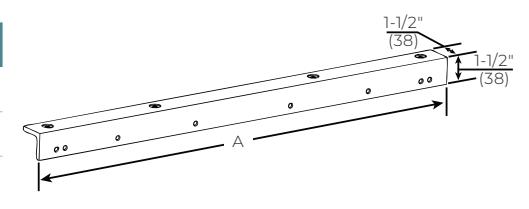
| Description | Part Number | A (Length) |
|---|---|---|
| 7100DAB | 29-9/16" (675) | |
| Drop angle bracket | 7100DAB-180 | 24-9/16" (621) |

FINISH
NORTON
ELECTRIFIED CLOSERS AND HOLDERS
HOW TO ORDER
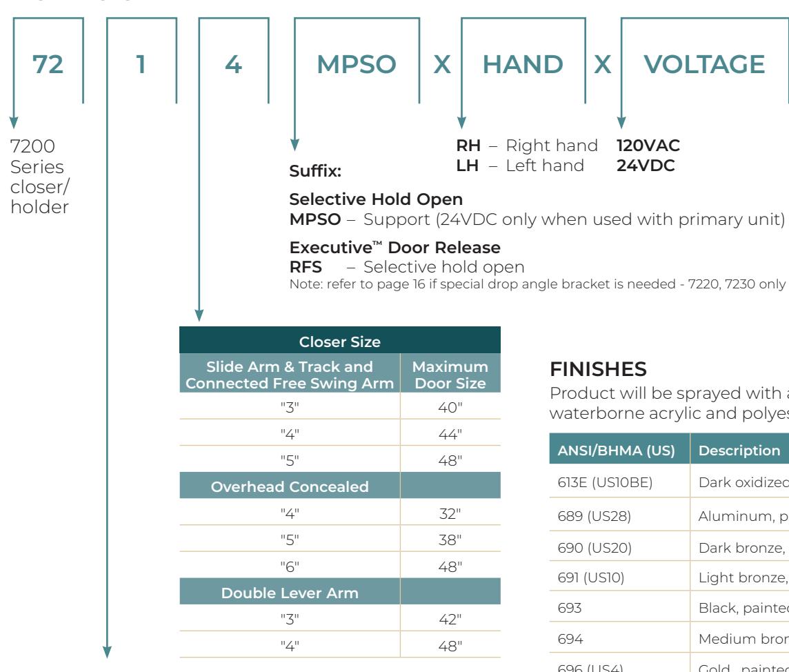
Specifies side of door unit is mounted on and the type of arm
Pull side
- Rigid slide arm & track; maximum reveal 1/8" (3mm)
"4" - Connected free swing slide arm & track; maximum reveal 1/8" (3mm)
"5" - Double egress slide arm & track; reveals 1/8"-3" (3-76mm) to 110°
"9" - Overhead concealed door closer with rigid slide arm & track
Push side
"2" - Double lever arm; reveals 2-3/4"-4" (70-120mm) to 180°; reveals 4"-7" (102-179mm) to 165°
"3" Double lever arm; reveals 4"-7" (102-179mm) to 180°
FINISHES
X
120VAC
24VDC
Product will be sprayed with a combination of waterborne acrylic and polyester powder coat.
VOLTAGE
X
| ANSI/BHMA (US) | Description |
|---|---|
| 613E (US10BE) | Dark oxidized satin bronze - equiv. |
| 689 (US28) | Aluminum, painted |
| 690 (US20) | Dark bronze, painted |
| 691 (US10) | Light bronze, painted |
| 693 | Black, painted |
| 694 | Medium bronze, painted |
| 696 (US4) | Gold , painted |
| BSP | Black suede powder coat |
| WSP | White suede powder coat |
ELECTRIFIED CLOSERS AND HOLDERS
INTRODUCTION
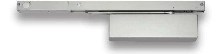
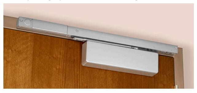
The Norton Rixson Power Track® Closer-Holders combine the functions of a single point electromechanical door holder with the proven reliability of a 7700 Series door closer. The track assembly contains an arm slide and solenoid operated hold open mechanism.
Units can be installed on a single door or a pair of doors when controlled by compatible UL listed detection equipment such as area ceiling detectors, pull stations, and remote alarm panels.
FEATURES
- Selective single-point hold open
- Fixed spring size 5
- Push or pull side mounting (closer mounted on door)
- Standard separate and independent latch, sweep, and backcheck intensity valves
- Spring loaded buffer block at the point of hold open prevents over travel of the arm slide and provides a cushioned dead stop
- Additional floor or wall stop is recommended
- Voltage: 24VDC or 120VAC
- NorGlide® closer fluid
- Non-handed
- Fail safe: solenoid will de-energize in the event of power failure
- Concealed or surface wiring
- 2-year limited warranty
BENEFITS
- Ideal for low ceiling clearance applications
- Installation based on the door angle needed
- Doors automatically close if activated by fire alarm
OVERVIEW
CERTIFICATIONS
- ANSI/BHMA A156.15 BHMA
- CAL FIRE, 3550-0944:0106
- Environmental Product Declaration (EPD)
- UL10C positive pressure up to 3 hours (1)
- UL-cUL listed
- Manufactured in an ISO 9001, ISO 14001 facility
ELECTRIFIED CLOSERS AND HOLDERS
EXPLANATION OF FEATURES
Selective Single-Point Hold Open:
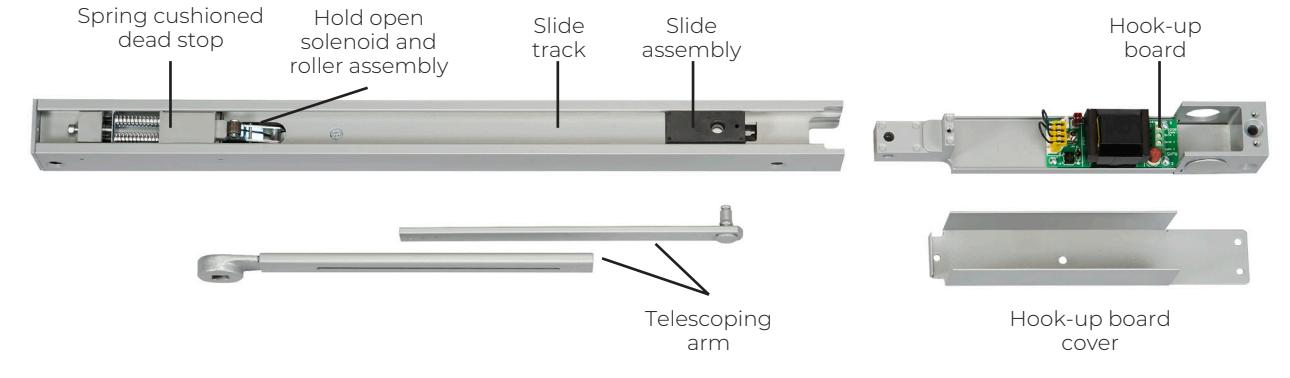
The Power Track® has one template position. The single-point hold open position is selected by adjusting the telescoping arm with a hex drive set screw. Hold open range is 85° thru 110° in approximately 3° increments.
Non-Handed:
Units are non-handed except when ordered with "DE" double egress arms. Choice of push or pull side installation: no prefix indicates pull side application. Prefix "P" for push side installation.
Choice of Supply Voltage:
Available in 24VAC/DC or 120VAC, 60Hz. voltages. Power to these devices must be within a range of (+) 10% (-) 15% of the stated voltage.
Fail Safe:
In the event of a power outage, the Power Track solenoid will be de-energized and the closer/holder will then operate as a normal door closer.
Wiring Option:
Both pull and push side applications will accommodate either concealed or surface wiring. The hook-up box will accept 3/4" (19mm) conduit. Each Power Track is supplied with a thin-walled conduit nut to attach the conduit clamp. The hook-up box base is prepared for surface wiring. State and local building codes will dictate the type of wiring.
Spring Cushioned Dead Stop:
A spring-loaded buffer block at the point of hold open prevents over travel of the arm slide and provides a cushioned dead stop. Use of an additional wall or floor stop is always recommended.
ORDERING VOLTAGES
| Model | # of Power Input Lines | Choices of Voltage Input | Can be used with |
|---|---|---|---|
| PTO-24 | 1 | 24 VAC/DC | Area smoke |
| PTO-120 | l | 120 VAC, 60Hz | detection system |
Operating voltage for the control of fire/smoke doors are specified by the architect, electrical engineer and alarm system engineer and/or contractor. Consulting with these sources will verify which operating voltage should be ordered.
"PTO" Support Units
- Hold open solenoid requires electrical power.
- Solenoid controlled by smoke detection equipment (ceiling detectors) or remote alarm panels.
- Available for operation on 24VAC/DC or 120VAC, 60Hz
- Hold open solenoid operates on direct current.
- Contains built-in rectifier that converts alternating current to direct current
ELECTRIFIED CLOSERS AND HOLDERS
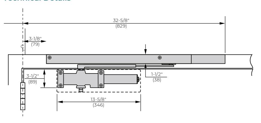
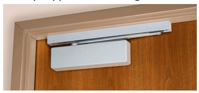
7705 POWER TRACK®
Pull (Hinge) Side Mounting
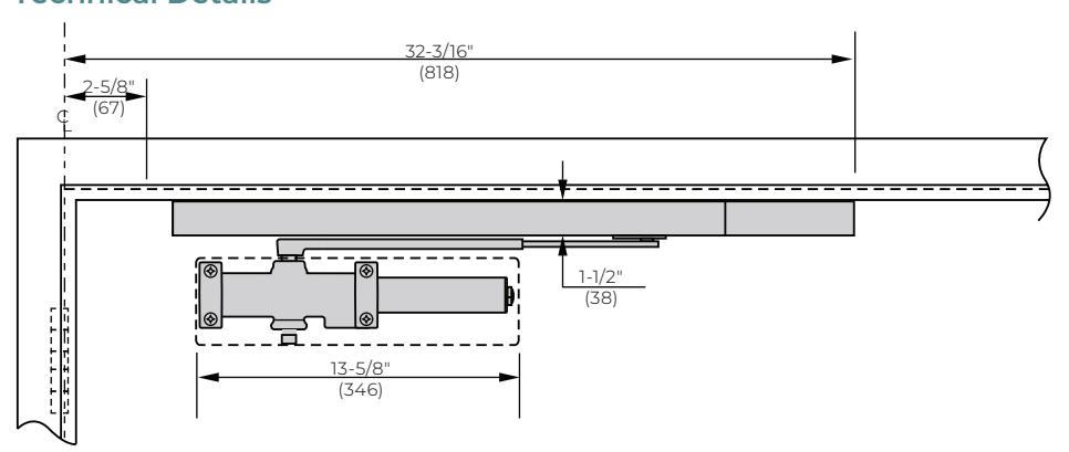
Technical Details
Door Size
|
Door(s) Opening Inches
(cm) |
Model Number | ||
|---|---|---|---|
| Max.* | Min.** | & Type | |
| Single Door | 48" (122) | 32" (81) | (1) 7705PTO Support Unit |
|
Pairs of
Doors |
96" (244) | 64" (163) |
(2) 7705PTO Support Units
(controlled by remote detection equipment) |
| Minimum Top Rail | ||
|---|---|---|
| Without Drop Plate | With 7786 Drop Plate | |
|
3-1/2"
(89mm) |
1-7/8"
(48mm) |
|
2-1/8& quot; (54mm) minimum ceiling clearance required for Power Track.
- * Maximum door size for door closer power.
- ** Minimum door opening for standard installation. Consult factory for door openings narrower than those shown.
Double egress doors: With reveals greater than 1/8" (3mm); a special handed arm for the pull (hinge) side Power Track is available. Accommodates reveals to 3" (76mm). Suffix "DE" to model number; specify hand.

ELECTRIFIED CLOSERS AND HOLDERS
P7705 POWER TRACK®
Push (Stop) Side Mounting
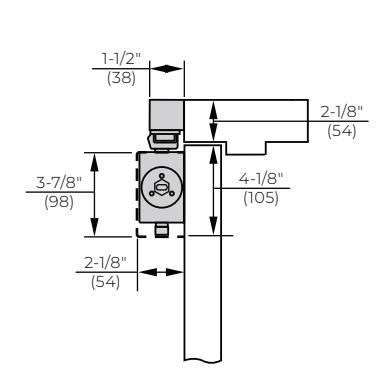
Technical Details
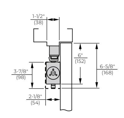
Door Size
| Door(s) Opening Inches (cm) | Model Number | ||
|---|---|---|---|
| Max.* | Min.** | & Type | |
| Single Door | 48" (122) | 33" (84) | (1) P7705PTO Support Unit |
|
Pairs of
Doors |
96" (244) | 64" (163) |
(2) P7705PTO Support
Units |
| Minimum Top Rail | ||
|---|---|---|
| With 7788 Drop Plate | ||
|
2-3/4"
(70mm) |
||
1-1/2& quot; (38mm) minimum frame soffit required for Power Track.
Consult factory for door openings narrower than those shown.
NOTE: Interference with other hardware such as vertical rod exit devices, magnetic locks, and door coordinators, etc., must be considered when selecting this product.
* Maximum door size for door closer power.
** Minimum door opening for standard installation.
ELECTRIFIED CLOSERS AND HOLDERS
ELECTRICAL INFORMATION
|
Model
Number |
No. Power
Input Lines* (Pairs) |
Operating
Voltage |
Amperage Draw Solenoid Coil |
|---|---|---|---|
|
7705PTO
P7705PTO |
- | 24VAC/DC | .090 @ 24VDC |
| I | 120VAC, 60Hz | .018 @ 120VAC |
* Number of input lines (pairs) required to supply operating voltage. This does not include signal or control lines (pairs) to alarm panels.
SUGGESTED SPECIFICATIONS
Closers for ______ doors shall be electromechanical closer-holder. Hold open to be achieved by electric solenoid locking of closer arm slide in its track. Track, arm, slide (and) solenoid (and integral smoke detector) to be contained in a single aluminum extrusion 1-1/2" (38mm) high, 1-1/2" (38mm) deep.
Closer shall be door mounted. Track and hold open mechanism shall be surface mounted to the frame face for application on the pull side of the door and frame soffit mounted for application on the push side of the door. Single point hold open shall be selective through a range of 85° to 110°. Hold open point to be achieved by adjustment of a telescoping closer arm
Closer shall be hydraulic with full rack and pinion enclosed in a cast aluminum alloy shell. Hydraulic fluid shall be non-gumming and non-freezing. Closer shall have two non-critical valves to independently regulate sweep speed and latch speed. It shall have an adjustable backcheck cushioning valve and an adjustable backcheck positioning valve. All valves shall be
adjustable with a hex-key. (Closer shall have spring power adjustment to permit 50% increase in closing power.) Closer to be enclosed in a molded full cover.
(Support units to be controlled by U.L. Listed Smoke Detection Equipment.) Units to be fail safe and close the door during an interruption to the electrical power. The hold open solenoid coil shall have a maximum amperage draw of (.090 Amps at 24 volts) (.018 Amps at 120 volts). Unit shall have a switch to permit testing of the releasing device function without alarming the system.
All wiring connections shall be made without the need of wire nuts or soldering. Support unit(s) shall require a (24VAC/DC) (120, 60Hz) power input. Supplier to coordinate electrical requirements with electrical and alarm system engineers. Wiring (and conduit) by others. Electromechanical Closer-Holder to be Norton Rixson Power Track® [(P)7700(PTO)].
ELECTRIFIED CLOSERS AND HOLDERS
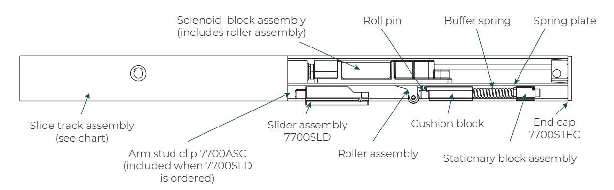
TRACK ASSEMBLIES
| Valhana | Part Number^ | ||
|---|---|---|---|
| Voltage | Hinge Side | Stop Side | |
| 24V | PTO24 | PPTO24 | |
Support unit track assemblies include track, slider assembly and solenoid block assembly. Hook-up box not included.
| Description | Part Number |
|---|---|
| Hook-up box cover kit | PTOHBCOV |
| Description | Voltage | Part Number |
|---|---|---|
| Hook-up boards | 24V | PTOPCB24 |
| 120V | PTOPCB120 |
PARTS
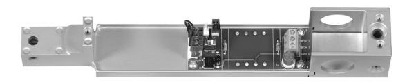
Hook-Up Box (shown less cover**)
** For identification purposes only – box is only supplied with cover
| Danasistias | Valtaria | Hook-Up Boxes^ | ||
|---|---|---|---|---|
| Description | Voltage | Hinge Side | Stop Side | |
| 6 | 24V | PTOHB24 | PPTOHB24 | |
| Support | 120V | PTOHB120 | PPTOHB120 | |
| Miscellaneous Parts | |||
|---|---|---|---|
| Description | Part Number | ||
| Fuse | PTO125V | ||
| Solenoid block assembly (24V) | PT24SOL | ||
|
Push side hook-up box plug
button |
P7700PB | ||
Support, 24V
ELECTRIFIED CLOSERS AND HOLDERS
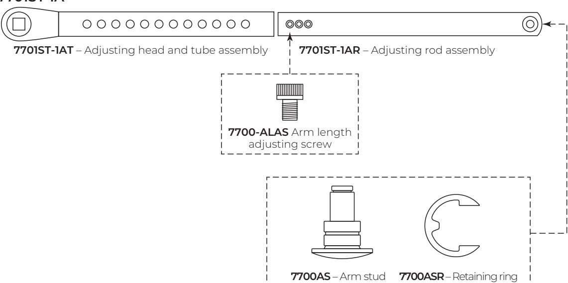
STANDARD ARM ASSEMBLY

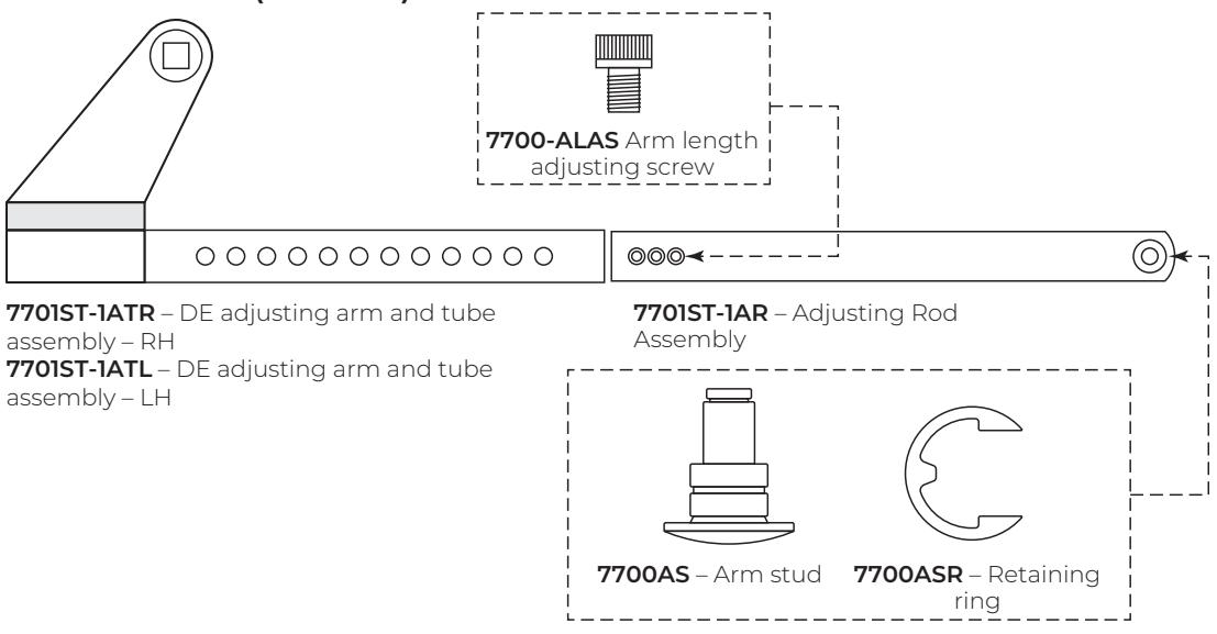
DOUBLE EGRESS ARM ASSEMBLY

Notes:
1 Includes arm length adjusting screw 7700-ALAS 2 Includes arm tube & adjusting rod assembly Mounting hardware included with all parts orders
ELECTRIFIED CLOSERS AND HOLDERS
HOW TO ORDER
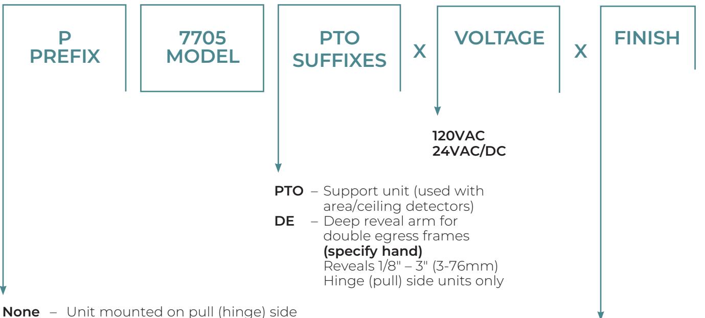
- None Unit mounted on pull (hinge) side of door; maximum reveal 1/8" (3mm) For greater reveals up to 3" (76mm) suffix "DE" to model number
- P Unit mounted on push (stop) side of door
FINISHES
Product will be sprayed with a combination of waterborne acrylic and polyester powder coat.
| ANSI/BHMA (US) | Description |
|---|---|
| 613E (US10BE) | Dark oxidized satin bronze - equiv. |
| 689 (US28) | Aluminum, painted |
| 690 (US20) | Dark bronze, painted |
| 691 (US10) | Light bronze, painted |
| 693 | Black, painted |
| 694 | Medium bronze, painted |
| 696 (US4) | Gold , painted |
| BSP | Black suede powder coat |
| WSP | White suede powder coat |
ELECTRIFIED CLOSERS AND HOLDERS
INTRODUCTION
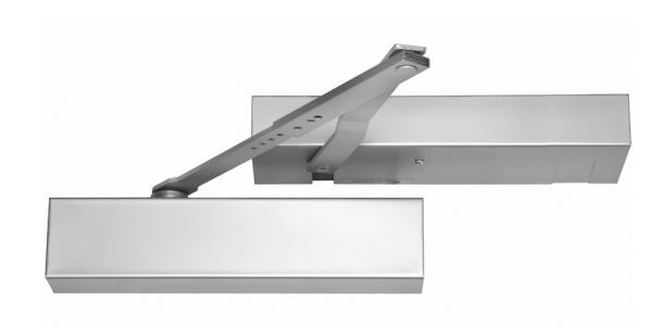
Designed for a variety of applications, fire/life-safety closers and holders protect people and property.
The single-point electromechanical Smok-Chek V can be mounted on the push or pull side of the door and is best suited for cross corridor doors. Checkmate 99, an electrified holder, is used with independent closers and can be mounted on the push or pull side of the door.
GENERAL INFORMATION
SMOK-CHEK® V
Electromechanical action
- Single point hold open
- More durable than electrohydraulic units
- To hold open at 90°, door must open to 93°
- Best suited for cross corridor doors
CHECKMATE<sup>®</sup> 99
Electromechanical action - no closer supplied
- For doors with floor closers or surface mounted door closers
- Single point hold open
- To hold open at 90°, door must open to 93°
- Best suited for cross corridor doors
Note: these products are not designed to be manually pulled out of hold open. If continual cycling is necessary, a separate switch to release should be used.
SPECIFICATIONS
Closer/Holders shall be Smok-Chek® V series. They should be electromechanical type. All holders shall open and hold up to 180°. Units shall have holder on the frame and closer on the door. Product with fall-off will not be acceptable.
Whenever floor closers are specified and an electromechanical hold open is needed, the product should be Checkmate® 99 . This separate holder will allow the doors to swing to 110°, depending on the type of closer being used.
ELECTRIFIED CLOSERS AND HOLDERS
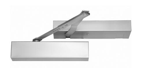
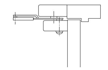
0600 PULL SIDE MOUNTING
Application
Cross corridor doors - swinging in the same direction
Features
- Single-point hold open
- Pull side mounting
- Non-handed
- Hold open range 85°-145°
- Mounts on a 2" header
- Doors up to 4'0"
- · Door weight: 250 lbs.
- Concealed switch disconnects hold open
- Adjustable spring surface closer
- Maximum reveal: 1/8"
- NorGlide® closer fluid
- 2-year limited warranty
Certifications
- UL-cUL fire-rated up to 3 hours
- CAL FIRE. 3550-0047:0015
Electrical Data
- 24VAC/DC 80ma
- 120VAC 17ma
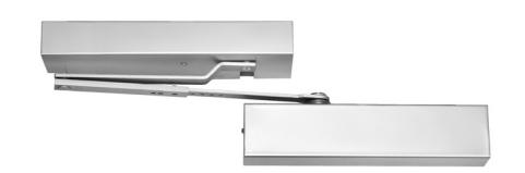
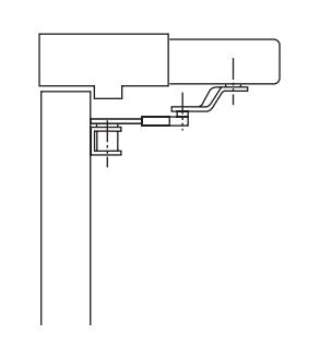
0601 PUSH SIDE MOUNTING
Application
Cross corridor doors – double egress – doors swinging in opposite directions
Features
- · Single-point hold open
- Push side mounting
- Non-handed
- Hold open range 85°-105°
- Mounts on a 2" header
- Doors up to 4'0"
- · Door weight 250 lbs.
- Concealed switch disconnects hold open
- Adjustable spring surface closer
- Maximum reveal: 3-1/2"
- For double egress doors with reveals from 3-1/2" up to 5-1/2" or on applications where doors need to swing 150°, use 550789 arm.
- NorGlide® closer fluid
- 2-year limited warranty
Certifications
- UL-cUL fire-rated up to 3 hours
- CAL FIRE, 3550-0047:0015
Electrical Data
- 24VAC/DC 80ma
- 120VAC 17ma
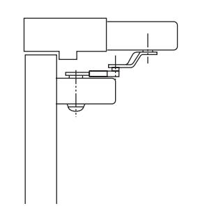
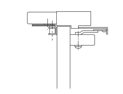
| Arm | Reveal |
Hold Open
Range |
|---|---|---|
| Standard | 3-1/2" | 85-105° |
| Deep | 3-1/2" | 85-150° |
| Reveal | 5-1/2" | 85-135° |
ELECTRIFIED CLOSERS AND HOLDERS
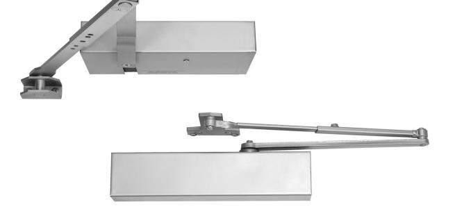
0602 HOLDER
Application
Cross corridor doors – swinging in the same direction
Features
- Single-point hold open
- Pull side mount for holder; push side mount for closer
- Non-handed
- Hold open range 85°-180°
- Mounts on a 2" header
- Doors up to 4'0"
- Door weight 250 lbs.
- Concealed switch disconnects hold open
- Adjustable spring surface closer
- Maximum reveal (pull side): 1/8"
- NorGlide® closer fluid
- 2-year limited warranty
Certifications
- UL-cUL fire-rated up to 3 hours
- CAL FIRE, 3550-0047:0015
Electrical Data
- 24VAC/DC 80ma
- 120VAC 17ma
0100 HOLDER
Application
Cross corridor doors – can be used with floor closers
Features
- Single-point hold open
- Pull side mount for holder
- No closer supplied
- Non-handed
- Hold open range 85°-180°
- Mounts on a 2" header
- Doors up to 4'0"
- Maximum door weight 250lbs.
- Maximum reveal: 1/8"
- 2-year limited warranty
Certifications
- UL-cUL fire-rated up to 3 hours
- CAL FIRE, 3550-0047:0015
Electrical Data
- 24VAC/DC 80ma
- 120VAC 17ma
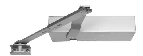
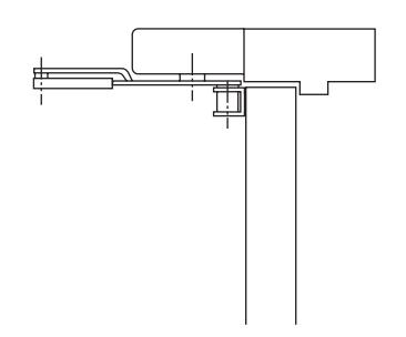

0101 HOLDER
Application
Cross corridor doors – double egress – doors swinging in opposite directions
Features
- Single-point hold open
- Push side mount for holder
- No closer supplied
- Non-handed
- Hold open range 85°-105°
- Mounts on a 2" header
- Doors up to 4'0"
- Door weight 250 lbs.
- Maximum reveal: 3-1/2".
- For double egress doors with reveals from 3-1/2" up to 5-1/2" or on applications where doors need to swing 150°, use 550789 arm.
- 2-year limited warranty
Certifications
- UL-cUL fire-rated up to 3 hours
- CAL FIRE, 3550-0047:0015
Electrical Data
- 24VAC/DC 80ma
- 120VAC 17ma
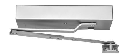
| Arm | Reveal |
Hold Open
Range |
|---|---|---|
| Standard | 3-1/2" | 85-105° |
|
Deep
Reveal |
3-1/2" | 85-150° |
| 5-1/2" | 85-135° |
ELECTRIFIED CLOSERS AND HOLDERS
HOW TO ORDER
X 120VAC VOLTAGE 120VAC 24VAC/DC
550789 OPTIONS 550789 Arm (0601, 0101 models only)
689 FINISH
0600 Pull side mounting0601 Push side mounting
0602 Holder on pull side/closer on push side
0100 Pull side mounting holder only 0101 Push side mounting holder only
| ANSI/BHMA (US) | Description |
|---|---|
| 689 (US28) | Aluminum, painted |
| 690 (US20) | Dark bronze, painted |
| 691 (US10) | Light bronze, painted |
| 696 (US4) | Gold, painted |
| BSP | Black suede powder coat |
| WSP | White suede powder coat |
X
PRODUCT COMPARISON CHART
| 0600 | 0601 | 0602 | 0100 | 0101 | |
|---|---|---|---|---|---|
| Application |
Cross corridor
doors (swinging in the same direction) |
Cross corridor
doors (swinging in the opposite direction) |
Cross corridor
doors (swinging in the same direction) |
Cross corridor
doors - can be used with floor closers |
Cross corridor,
double egress doors - (doors swing in opposite directions) |
| Closer included | • | • | • | ||
| Pull side mounting | • | Holder | Holder | ||
|
Push side
mounting |
• | Closer | Holder | ||
| Hold open range | 85-145° | 85-105° | 85-180° | 85-180° | 85-105° |
| Maximum reveal 1 | 1/8" | 3-1/2" | 1/8" | 1/8" | 3-1/2" |
1 When ordered with special arm 550789, additional reveals from 3-1/2" up to 5-1/2" may be accommodated (0601, 0101 only).
NORTON
SMOK-CHEK® V

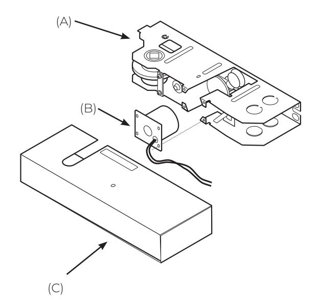
PARTS DRAWING
(A) Holder assembly 120VAC 550100 550101 24VAC/DC
(B) Magnet 930105 930106
120VAC 24VAC/DC
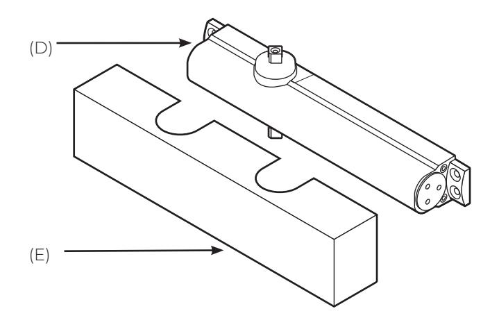
- (C) Holder cover 550106-*
- (D) Closer body 85010163-*
- (E) Closer cover 233069K*
Screw Packs
550221-* for models with closers 550131-* for models without closers
ELECTRIFIED CLOSERS AND HOLDERS
PARTS DRAWING
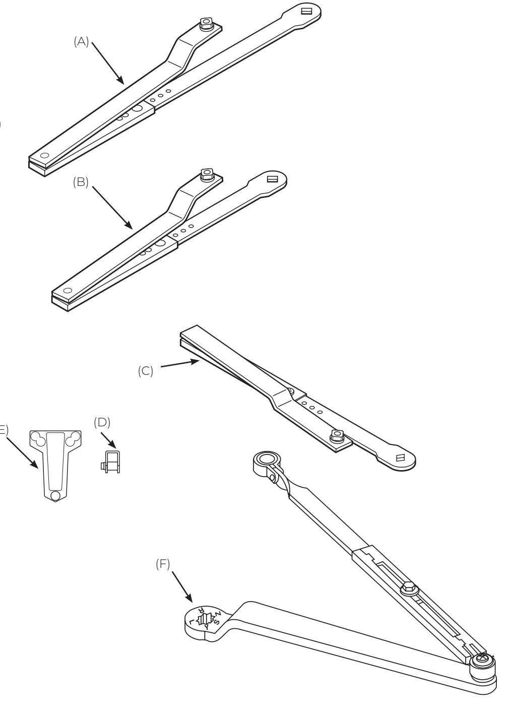
- (A) Deep reveal push side arm 550789-*
- (B) Push side arm 550136K*
- (C) Pull side arm 550120K-*
- (D) Door pivot bracket (used with 0602 closers) 565118T689
- (E) PA bracket (used with 0602 closers) 40-1600-0450-078
- (F) Arm (used with 0602 closers) 20-7700-0192-*
*specify finish
CHECKMATE® 99
ELECTRIFIED CLOSERS AND HOLDERS
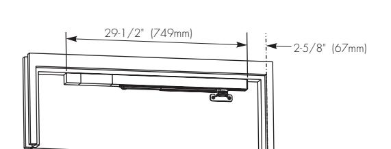
99-726 PUSH SIDE MOUNT
Application
Used with independent closers
Features
- Single-point hold open
- Push side mounting
- Surface mounted
- Non-handed
- Single acting
- Surface or concealed wiring
- Holding force: 25-35lbs.
- Hold open: 85° 110°
- For doors 2' 8" x 4' 0"
- 2-year limited warranty
Certifications
UL-cUL fire-rated up to 3 hours
Electrical Data
120VAC / 24VAC/DC 90mA
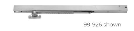
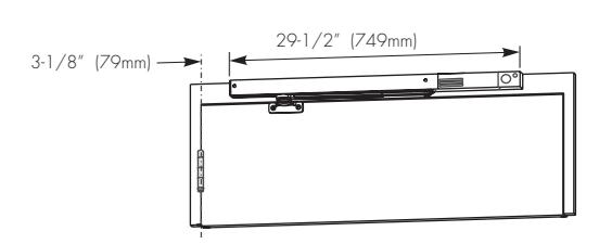
99-926 PULL SIDE MOUNT
Application
Used with independent closers
Features
- Single-point hold open
- Pull side mounting
- Surface mounted
- Non-handed
- Single acting
- Surface or concealed wiring
- Holding force: 25-35lbs.
- Hold open: 85° 110°
- For doors 2' 8" x 4' 0"
- 2-year limited warranty
Certifications
UL-cUL fire-rated up to 3 hours
Electrical Data
• 120VAC/24VAC/DC 90mA
CHECKMATE® 99
ELECTRIFIED CLOSERS AND HOLDERS
HOW TO ORDER
99-726 MODEL
99-726 Push side mounting 99-926 Pull side mounting
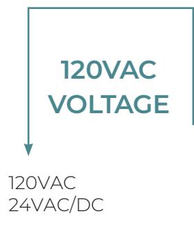
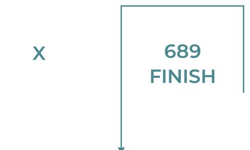
| ANSI/BHMA (US) | Description | |
|---|---|---|
| 689 (US28) | Aluminum, painted | |
| 690 (US20) | Dark bronze, painted | |
| 691 (US10) | Light bronze, painted | |
| 696 (US4) | Gold, painted | |
| BSP | Black suede powder coat | |
| \//SD | White suede powder coat | |
CHECKMATE® 99

PARTS DRAWINGS
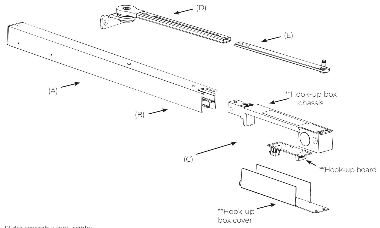
- (A) Slider assembly (not visible) 20-0099-0337-500
- (B) Channel (for 99-726) 20-0099-0608-* (24V)
- (B) Channel (for 99-926) 20-0099-0609-* (24V)
- (C) Hook-up box assembly (for 99-726) 20-0099-0604-* (24V) 20-0099-0605-* (120V)
- (C) Hook-up box assembly (for 99-926) 20-0099-0600-* (24V) 20-0099-0601-* (120V)
- (D) Arm bracket & tube 20-0099-0516-*
- (E) Adjusting rod 20-0099-0343-*
Screw Kit
20-0040-0534-*
* specify finish
** Not sold separately. Part of hook-up box assembly
The ASSA ABLOY Group is the global leader in access solutions. Every day, we help billions of people experience a more open world.
ASSA ABLOY Opening Solutions leads the development within door openings and products for access solutions in homes, businesses and institutions. Our offering includes doors, frames, door and window hardware, mechanical and smart locks, access control and service.
Since 1880, Norton Rixson door controls have been an integral part of schools, hospitals and businesses around the globe. When you need products and people that perform at the highest level, rely on Norton Rixson – From Open to Close.
NORTON RIXSON | WWW.NORTONRIXSON.COM
3000 Highway 74 East | Monroe, NC 28112 | Tel: 1 877 974 2255
ASSA ABLOY OPENING SOLUTIONS DOOR SECURITY SOLUTIONS CANADA | www.assaabloydss.ca
160 Four Valley Drive | Vaughan, Ontario, L4K 4T9 Canada | Tel: 800 461 3007