Norton Rixson 9500 Series Door Closer, Unitrol Arm, Non-Hold Open or Hold Open Installation Instructions_80-9395-9514-020
Open the original PDF document
View PDF

RIXSON Multi-Sized 1 thru 6 W ® ith Unitrol Arms 9500 Series Installation Instructions

IMPORTANT:
- An improperly installed or incorrectly adjusted door closer may cause property damage or personal injury and will void product warranty.
- To avoid personal injury, DO NOT DISASSEMBLE THIS DOOR CLOSER BODY .
- Door closers must be securely fastened to a properly reinforced door and frame with fasteners provided.
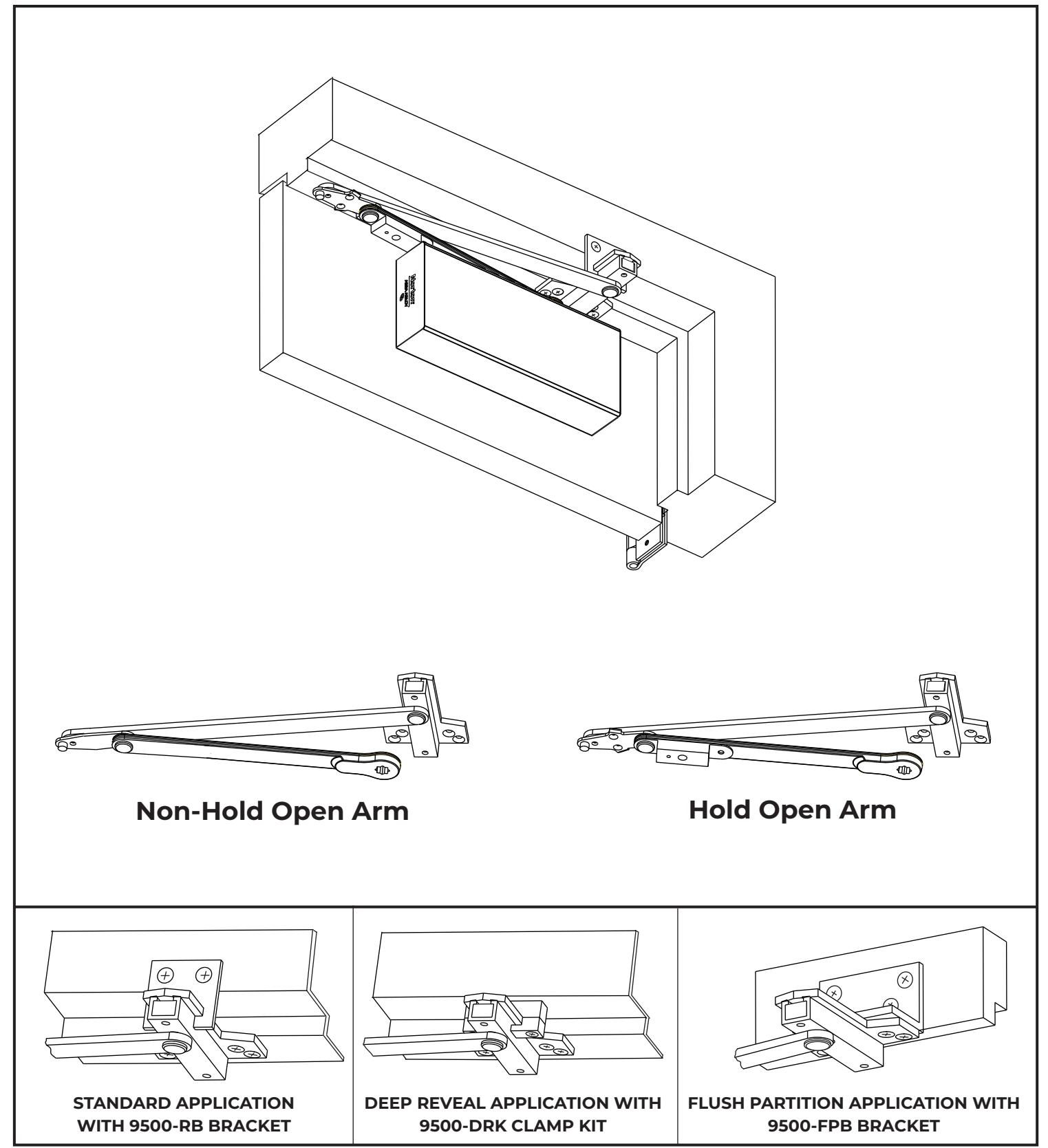
- Door closers with a HOLD OPEN ARM are not permitted to be installed in fire door assemblies.
- Door and frame must be specifically templated for 85°, 90°, 95°, 100°, 105°, or 110° door swing.
| Size of Door & Door Closer | ||||||||
|---|---|---|---|---|---|---|---|---|
|
Type
of Installation |
Interior |
Exterior
In -swinging |
Exterior
Out -swinging |
Recommended
Closer Size |
**Max.
Opening Force lbs/f |
|||
| 2'4" | 1 | 8 | ||||||
| 2'6" | 2 | 14 | ||||||
| Parallel | 3'0" | 2'6" | 3 | 16 | ||||
| Arm | 3'6" | 3'0" | 4 | 22 | ||||
| 4'0" | 3'6" | 5 | 24 | |||||
| 4'6" | 4'0" | 6 | 26 | |||||
TO DETERMINE HAND OF YOUR DOOR:

** NOTE: These forces are for standard templating with bearing type hinges and do not account for pressure differentials and draft.

3

| Preparation for Fasteners | Figure 2 | |||
|---|---|---|---|---|
| Fasteners | Door or Frame | Drill-Sizes | ||
| #32 17 Calf Drilling Carry |
Aluminum
or Metal |
No drill required | ||
| Standard | #12-14 Self-Drilling Screw | | Door or Frame | 3/16 (4.30) | |
| 1/4 - 20 machine screw | Metal |
Drill: #7 (0.201" dia.)
Tap: 1/4" - 20 |
||
| Optional |
Sleeve nuts and bolts
1-9/32 (33) = 1-3/8 (35) Door Thk. 1-21/32 (42) = 1-3/4 (44) & Over Dr. Thk. |
3/8 (9.5) door face | ||
| 3/8 (9.5) through | ||||
| Through-bolts and grommet-nuts | All | 3/8 (9.5) dia. x | ||
Note: Wood doors/frames: drill 1/8" (3.2) pilot hole when using Self-Drilling Screws.
Always consult door/frame manufacturer for fastener compatibility with the material of their door/frame.
- · It is recommended that the door on which the door closer will be installed be hung on ball bearing hinges. Door must swing freely.
- A separate door stop, supplied by others, is recommended to prevent damage to the door closer, closer arm, or to the door, frame, or adjacent walls.
- Door and Frame must be properly reinforced, or use of special fasteners employed, to prevent mounting screws from pulling out.
- All dimension s are given in inches with corresponding metric dimensions (millimeters) in parentheses.

Parallel Arm Template
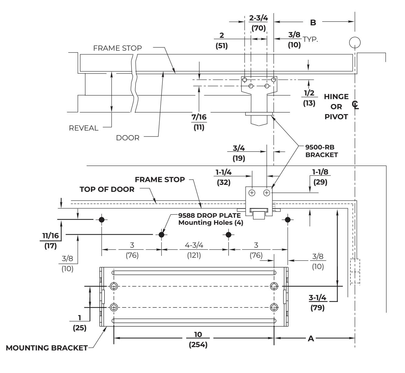
Standard Application with 9500-RB Bracket Template
NOTES:
- Check hand of door, see page 2.
- Right Hand Application Shown. Left Hand Opposite.
- Dimensions given in inches (mm). Do Not Scale Drawing.
- Closer must be installed mounted level to ensure proper closer performance.
Frame Reveals 1-7/8" to 4-5/8" (48mm to 117mm)
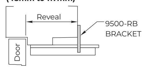
Parallel Arm Template
Deep Reveal Frame Template Application With 9500-DRK Clamp Kit
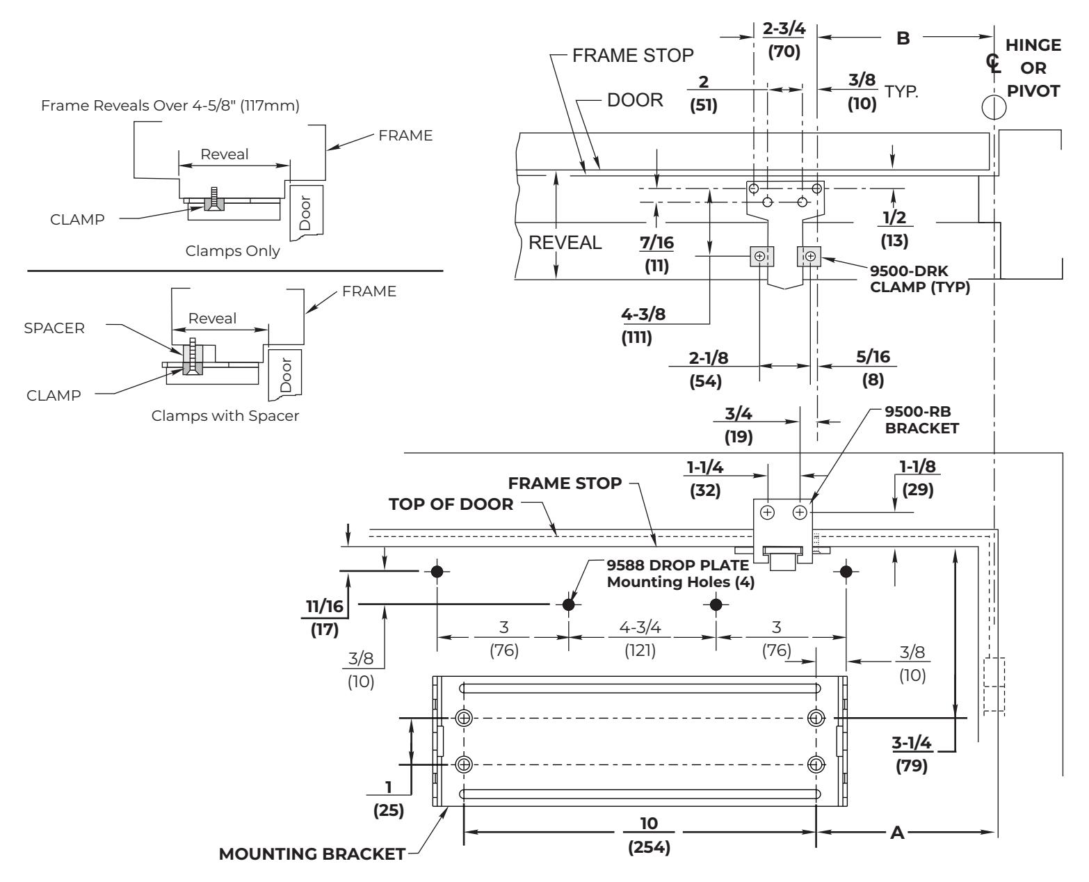
NOTES:
- Check hand of door, see page 2.
- Right Hand Application Shown. Left Hand Opposite.
- Dimensions given in inches (mm). Do Not Scale Drawing.
- Closer must be installed mounted level to ensure proper closer performance.

Parallel Arm Template
Flush Partition Frame Template Application With 9500-FPB Bracket
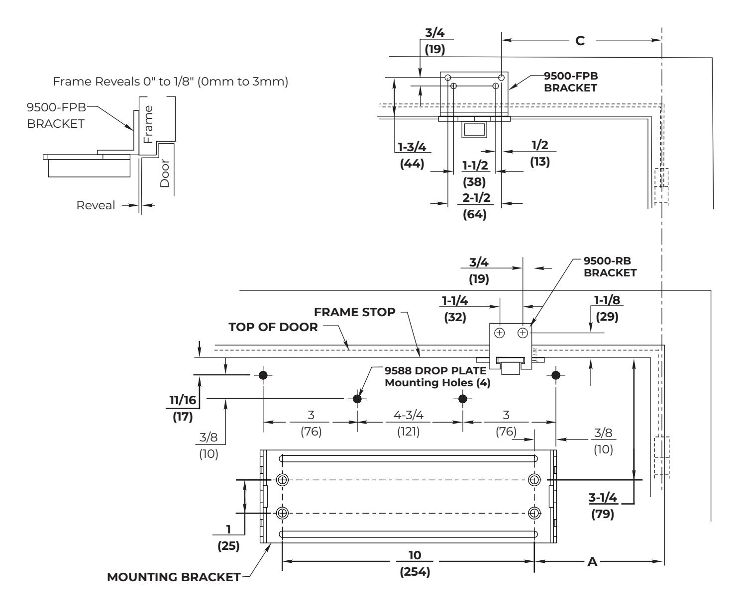
NOTES:
- Check hand of door, see page 2.
- Right Hand Application Shown. Left Hand Opposite.
- Dimensions given in inches (mm). Do Not Scale Drawing.
- Closer must be installed mounted level to ensure proper closer performance.

Parallel Arm Installation Sequence
NOTES:
- See chart to select degree of door opening and door width for your door. Then determine frame condition: STANDARD & DEEP REVEAL (Use Dims A & B) or FLUSH PARTITION (Use Dims A & C)
- MINIMUM TOP RAIL for Standard Application: 5" (127mm)
- MINIMUM TOP RAIL for Drop Plate Application: 2" (51mm)
| *Dimension "C" is only used for Flush Partition application (page 3). | ||||||||||
|---|---|---|---|---|---|---|---|---|---|---|
| Opening |
DOORS 28" TO 32"
9100-11 NHO ARM 9100-1 HO ARM |
DOORS 33" TO 41"
9100-13 NHO ARM 9100-3 HO ARM |
DOORS 42" TO 48"
9100-14 NHO ARM 9100-4 HO ARM |
|||||||
|
HOLD
OPEN |
DEAD
STOP |
Dim. A | Dim. B | *Dim. C | Dim. A | Dim. B | *Dim. C | Dim. A | Dim. B | *Dim. C |
| 85° | 90° | 5-3/4 (146) | 9-3/4 (248) | 9-7/8 (251) | 8-1/8 (206) | 11-7/8 (302) | 12 (305) | 10-1/4 (260) | 14-1/4 (362) | 14-3/8 (365) |
| 90° | 95° | 5-1/4 (133) | 9-1/4 (235) | 9-3/8 (238) | 7-5/8 (194) | 11-3/8 (289) | 11-1/2 (292) | 9-3/4 (248) | 13-3/4 (349) | 13-7/8 (352) |
| 95° | 100° | 4-3/4 (121) | 8-3/4 (222) | 8-7/8 (225) | 7-1/8 (181) | 10-7/8 (276) | 11 (279) | 9-1/8 (232) | 13-1/8 (333) | 13-1/4 (337) |
| 100° | 105° | 4-3/8 (111) | 8-3/8 (213) | 8-1/2 (216) | 6-5/8 (168) | 10-3/8 (264) | 10-1/2 (267) | 8-1/2 (216) | 12-1/2 (318) | 12-5/8 (346) |
| 105° | 110° | 4 (102) | 8 (203) | 8-1/8 (206) | 6-1/4 (159) | 10 (254) | 10-1/8 (257) | 8 (203) | 12 (305) | 12-1/8 (308) |
| 110° | 115° | 3-3/4 (95) | 7-3/4 (197) | 7-7/8 (200) | 6 (152) | 9-3/4 (248) | 9-7/8 (251) | 7-5/8 (194) | 11-5/8 (295) | 11-3/4 (298) |
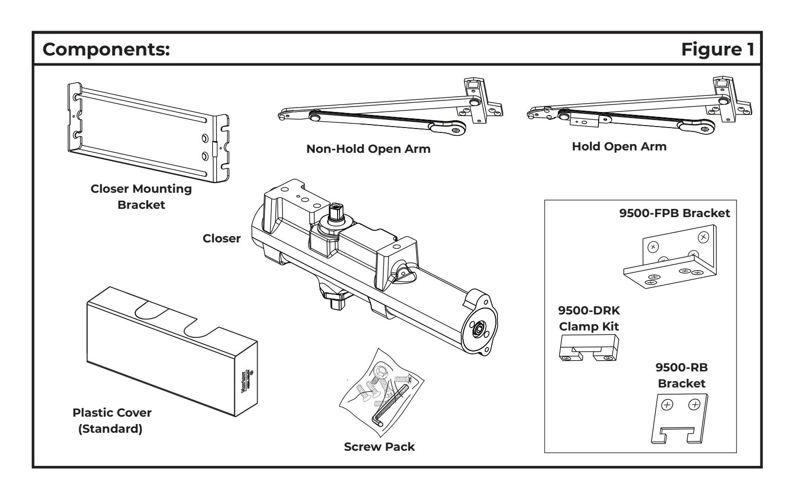
- Select angle of opening and use dimensions shown in template to locate 4 holes on door for Closer Mounting Bracket (or 4 holes for optional drop plate) and 4 holes on jamb for arm bracket (additional holes required for optional brackets). For applications that are different from above, a separate template will be supplied for door and frame preparation.
- Prepare door and frame for fasteners using "Preparation for Fasteners" chart, Figure 2, Page 4.
- Fasten Closer Mounting Bracket to door. Fasten optional drop plate to door, only if it is required for the door conditions.
- Install closer body with tube end TOWARDS hinge, with valves:
DOWN for Left Hand door UP for Right Hand door
- · Attach arm to door frame.
- Connect arm to closer. Using hex wrench provided, turn closing speed and latching speed valves clockwise until completely closed. DO NOT OVER TIGHTEN.
Open door to approximately 60°. Using wrench on underside of spindle, rotate spindle approximately 135° toward hinge edge of door. Install arm washer on spindle, then install arm at approximately a 90° angle to door. Reopen CLOSING SPEED VALVE. Install and tighten 5/16 Hex Head Arm Washer and Screw Assembly.
LEFT HAND DOOR SHOWN BELOW ALL ANGLES SHOWN ARE APPROXIMATE
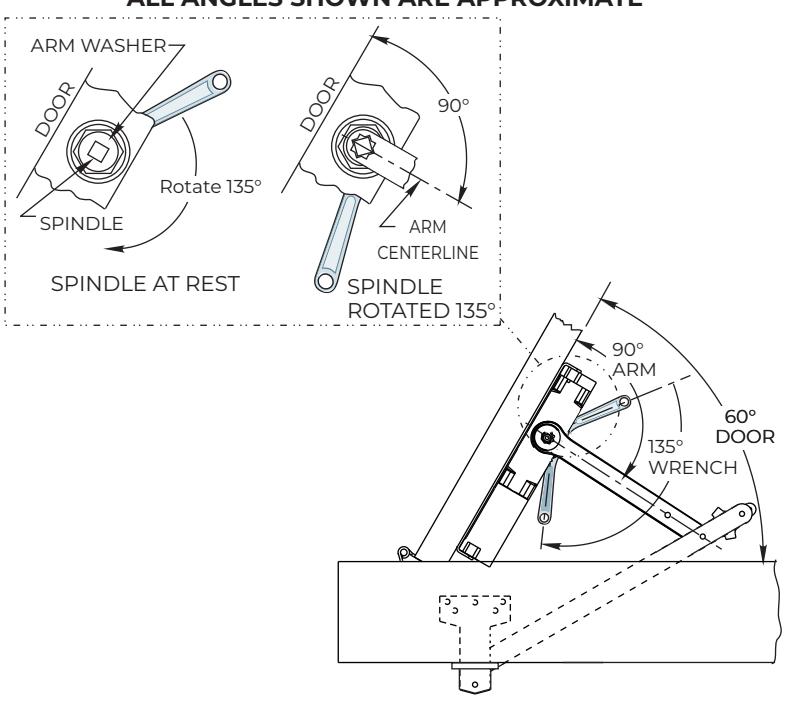
Make closer adjustments using information on page 9, then install closer cover.

Unit Adjustment
Spring Power Adjustment
Locate spring power adjuster from Illustration below Size 1 thru 6 Adjustment See Chart
SPRING POWER ADJUSTMENT CHART
- All 9500 closers are factory set at an approximate Size 3.
- Adjust closer as necessary for door size using this chart.
- Readjustment may be required to suit prevailing conditions.
| Size of Do | Spring Power | ||||
|---|---|---|---|---|---|
| Interior |
Exterior
In Swing |
Exterior
Out Swing |
Adjustment
No. Full Turns Clockwise |
Equivalent
Closer Size (Approx.) |
|
| 2' 4" (712) | 2'6" (764) | 2-7 | 3 | ||
| 2' 6" (764) | 3'0" (915) | 7-11 | 4 | ||
| 3' 0" (915) | 3'6" (1067) | 2'6" (764) | 11-15 | 5 | |
| 3' 6" (1067) | 4'0" (1219) | 3'0" (915) | 15-17 | 6 | |
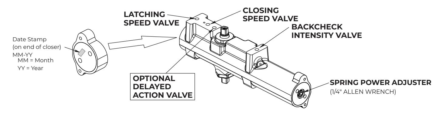
Closing Speed Valve (1/8 Allen Wrench Provided)
Factory preset for typical doors.
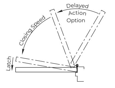
To adjust speed of door closing from fully open to a position 2" to 5" from closed, turn Closing Speed Valve CLOCKWISE to SLOW closing, COUNTER-CLOCKWISE to SPEED closing.
Latching Speed Valve (1/8 Allen Wrench Provided)
Factory preset for typical doors.
After closing speed has been obtained, turn latching speed valve CLOCKWISE to SLOW latching or COUNTER-CLOCKWISE to SPEED latching for last 2" to 5" of door travel.
NOTE : Set combination of CLOSING and LATCHING speeds to between 3 and 7 seconds Use of door by handicapped, elderly or small children may require even greater closing time.
Delayed Action Valve (1/8 Allen Wrench Provided)
Factory preset for typical doors.
Turn valve CLOCKWISE to SLOW closing, COUNTER-CLOCKWISE to SPEED closing. Delayed action may be adjusted from 20 seconds to 90 seconds, depending on degree of door swing. Delay occurs at the beginning of the door closing cycle from fully open down to 70°, where the closing speed valve then begins its control.
Backcheck Intensity Valve
Factory preset for typical doors.
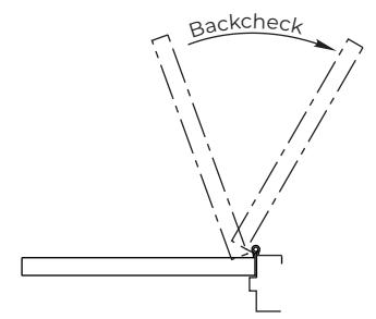
Turn valve COUNTER-CLOCKWISE to reduce backcheck or CLOCKWISE to increase backcheck. (Backcheck should be set to give a soft cushioning action, not a sudden stop.)
The ASSA ABLOY Group is the global leader in access solutions. Every day we help people feel safe, secure and experience a more open world.

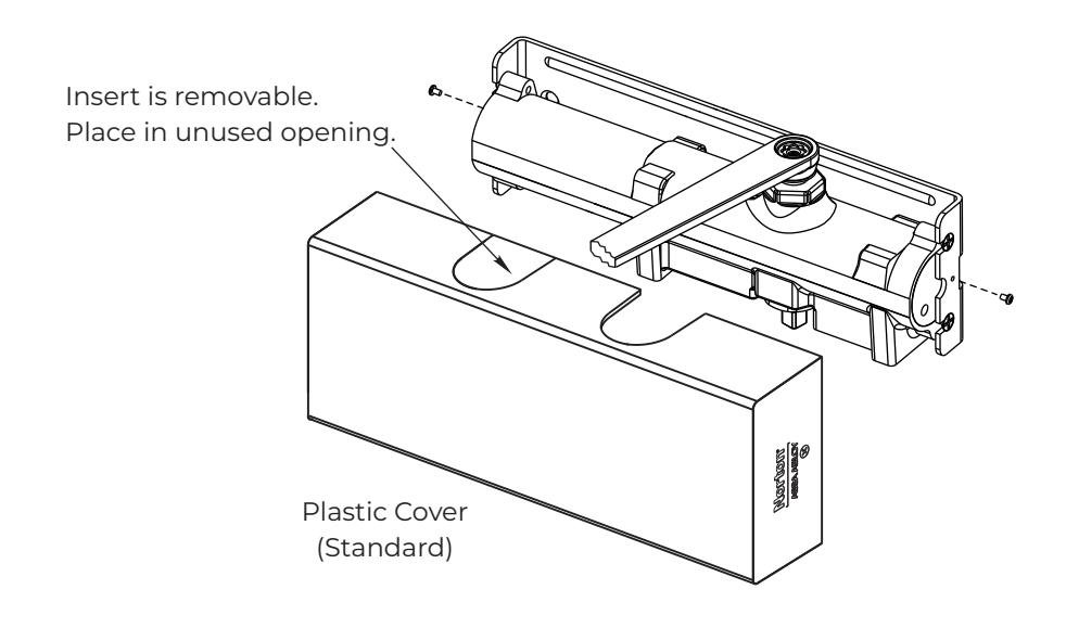
Installing Cover
- Slip cover over closer.
- Hold tightly against Closer Mounting Bracket surface.
- Secure on each side with 6-32 x 1/4" screws.
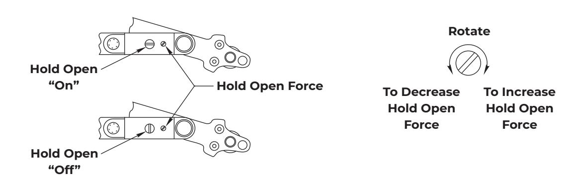
Hold Open Adjustments