Norton Rixson 78 BF Series Door Closer UNI78-BF, UNI78-BFH, Unitrol Arm, Non-Hold Open or Hold Open Installation…_80-9349-1040-020
Open the original PDF document
View PDFInstallation Instructions

Unitrol® Parallel Arm Door Controls Series UNI-78B/F Series UNI-78B/FH Non-Hold Open or Hold Open
- Use these instructions for installing all models of these series on 1-3/4" (45mm) doors hung on 4-1/2" (114mm) wide hinges or 3/4" (19mm) offset pivots.
- DOOR WIDTH determines the location of the closer. Use ONLY the template chart corresponding to your door width.
- Use ONLY the dimensions given in each template chart for the door total OPENING angle or the HOLD OPEN angle desired.
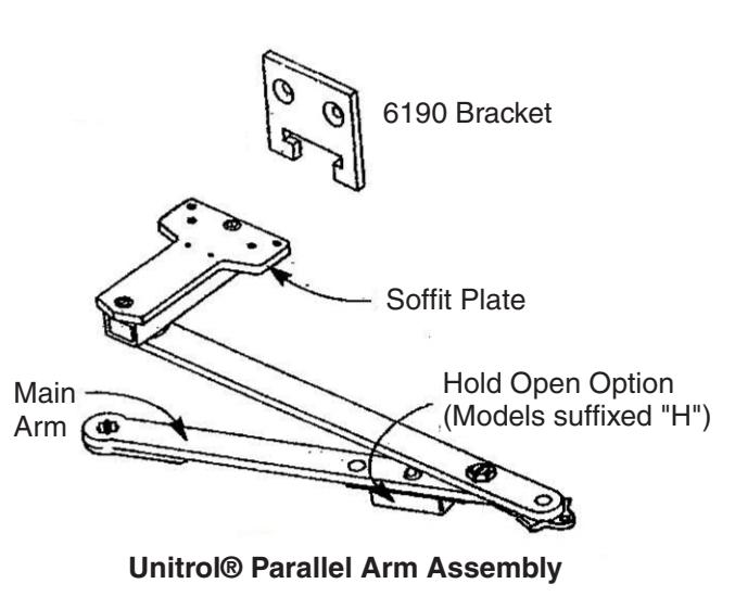
- Unitrol® parallel arms are supplied in one of three lengths, according to door width specified on order. To verify that the ARM you have is CORRECT FOR THE DOOR WIDTH, check the number stamped on the arm against the chart below.
|
Door
Width |
Non-Holder Arm | Hold Open Arm | |
|---|---|---|---|
|
28" - 32"
(0.70 - 0.80 m) |
6130-17 | 6130-7 | |
|
33" - 41"
(0.85 - 1.00 m) |
6130-18 | 6130-8 | |
|
42" - 48"
(1.05 - 1.20 m) |
6130-19 | 6130-9 | |
Components

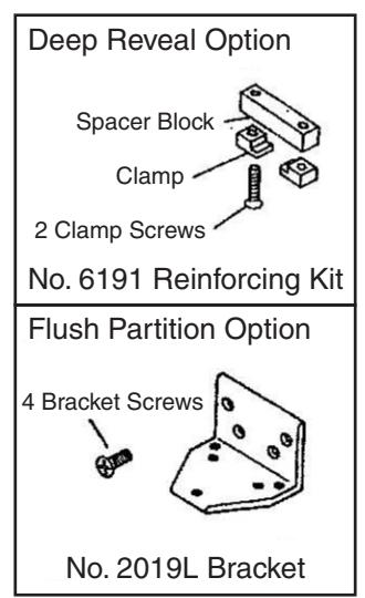
1-4-20 Machine Screw #14 Type "A" Screw 6 each, to mount soffit plate and 6190 bracket
Frame Template for 1-7/8" to 4-5/8" Reveals Door Template Typical for All Installations
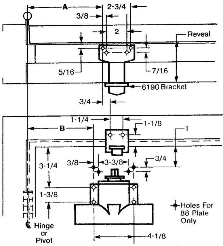
| DIMENSIO | NS FOR | DOORS 28" TO | 32" WIDE | |
|---|---|---|---|---|
| Opening | Dimension | Dimension | ||
| Hold-Open | Stop | Α | В | |
| 85° | 90° | 10-3/8 | 11-5/8 | |
| 90° | 95° | 9-3/4 | 11 | |
| 95° | 100° | 9-3/8 | 10-1/2 | |
| 100° | 105° | 8-3/4 | 10 | |
| 105° | 110° | 8-1/4 | 9-1/2 | |
| 110° | 115° | 77/8 | 9-1/8 | |
| DIMENSIO | NS FOR | DOORS 33" TO | 0 41" WIDE | |
|---|---|---|---|---|
| Opening | Dimension | Dimension | ||
| Hold-Open | Stop | Α | В | |
| . 85° | 90° | 12-7/8 | 14 | |
| 90° | 95° | 12-1/4 | 13-3/8 | |
| 95° | 100° | 11-5/8 | 12-3/4 | |
| 100° | 105° | 11 | 12-1/8 | |
| 105° | 110° | 10-1/2 | 11-5/8 | |
| 110° | 115° | 10-1/8 | 11-1/4 | |
| DIMENSIO | NS FOR | DOORS 42" TO | O 48" WIDE | |
|---|---|---|---|---|
| Opening | Dimension | Dimension | ||
| Hold-Open | Stop | Ą | В | |
| 85° | 90° | 15-3/8 | 16-3/8 | |
| 90° | 95° | 14-1/2 | 15-1/2 | |
| 95° | 100° | 13-3/4 | 14-3/4 | |
| 100° | 105° | 13-1/8 | 14-1/8 | |
| 105° | 110° | 12-5/8 | 13-5/8 | |
| 110° | 115° | 12-1/8 | 13-1/8 | |
Template Information

- Door template is typical for all installations.
- ASSA ABLOY
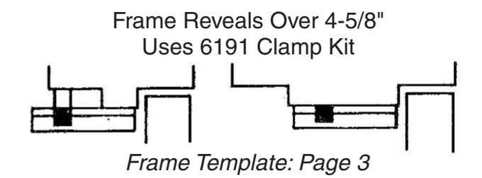
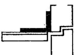
- Frame template must be selected according to reveal.
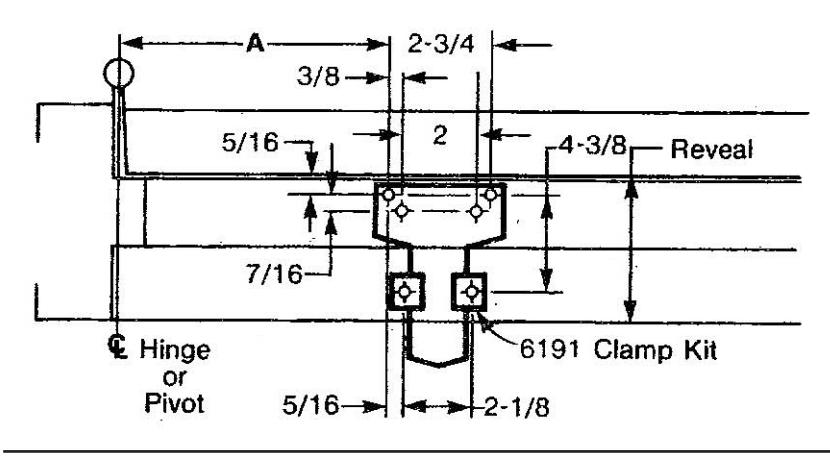
1-7/8" to 4-5/8" Frame Reveals Uses 6190 Bracket
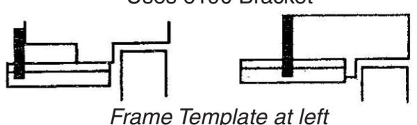
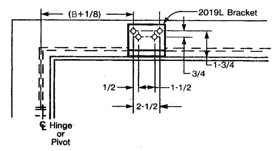
Flush Partitions Uses 2019L Bracket
Frame Template: Page 3
- Dimension Charts on this page are typical for all templates.
- Do not scale drawing.
- Left hand door shown.
- Dimensions are in inches.
- Metric conversion chart below.
- Fastener specifications on Page 3
| inches | mm | inches | mm | inches | mm | inches | mm |
|---|---|---|---|---|---|---|---|
| 5/16 | 8.0 | 2 | 50.8 | 9-3/4 | 248 | 12-7/8 | 327 |
| 3/8 | 9.5 | 2-3/4 | 69.9 | 10 | 254 | 13-1/8 | 333 |
| 7/16 | 11.1 | 3-1/4 | 83 | 10-1/8 | 257 • | 13-3/8 | 340 |
| 1/2 | 12.7 | 3-3/8 | 85.7 | 10-3/8 | 263 | 13-5/8 | 346 |
| 3/4 | 19.1 | 4-1/8 | 104.8 | 10-1/2 | 267 | 13-3/4 | 349 |
| 1 | 25 | 4-5/8 | 117 | 11 | 279 | 14 | 356 |
| 1-1/8 | 29 | 7-7/8 | 200 | 11-1/4 | 288 | 14-1/8 | 358 |
| 1-1/4 | 31.8 | 8-1/4 | 209 | 11-5/8 | 295 | 14-1/2 | 368 |
| 1-3/8 | 34.9 | 8-3/4 | 222 | 12-1/8 | 308 | 14-3/4 | 375 |
| 1-1/2 | 38.1 | 9-1/8 | 231 | 12-1/4 | 311 | 15-3/8 | 391 |
| 1-5/8 | 41 | 9-3/8 | 238 | 12-5/8 | 321 | 15-1/2 | 394 |
| 1-7/8 | 48 | 9-1/2 | 241 | 12-3/4 | 324 | 16-3/8 | 416 |
ASSA ABLOY, the global leader in door opening solutions
Frame Template for Reveals Over 4-5/8" Door Template on Page 2
Frame Template for Flush Partitions Door Template on Page 2
Installation Sequence

1. Read Front Page.
Installation ground rules and components identification are on this page.
2. Match closer to door hand.
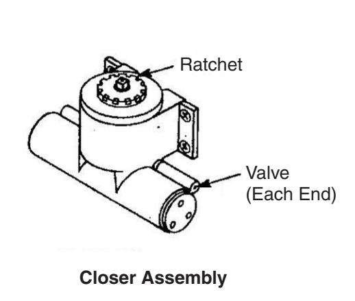
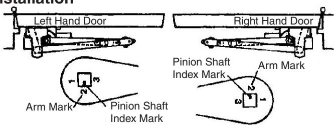
See "Typical Installation" figure below and verify that you have a closer of the same hand as the door (rachet should wind spring clockwise for LH, counterclockwise for RH closers). To change hand of closer, see Page 4.
3. Match hardware to opening.
Follow "Template Information" on Page 2.
4. Mark mounting holes location.
Use dimensions for hold open or door stop angle desired. Mark position fo 4 holes on door for closer (or drop plate) and 6 holes on frame for soffit plate (or 4 for 2019L angle bracket).
- 5. Prepare holes for fasteners. See chart below.
- 6. Mount closer to door.
Drop plate first, if used.
7. Install arm on pinion top.
Align main arm number "2" with index mark on pinion shaft. Fasten with arm screw. See "Typical Installation" figure below. Do not engage dog to ratchet.
8. Mount arm to frame.
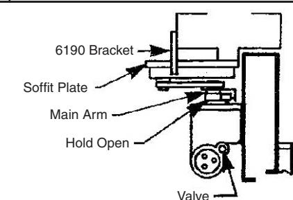
Fasten soffit plate (or angle bracket if flush partition) to frame. Mount 6190 bracket or 6191 clamps to hold soffit plate flat.
9. Set closing tension.
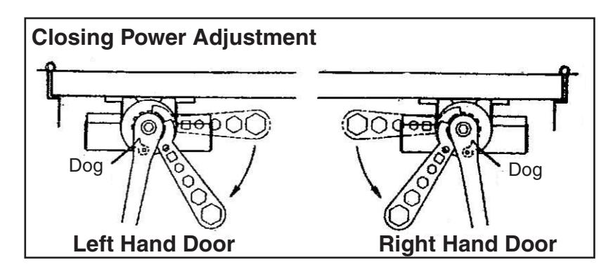
Wind spring 3 to 10 notches from rest positon (wrench supplied) and engage arm dog in ratchet notch to hold spring preload. Spring winds clockwise for left hand doors, counterclockwise for right hand doors.
10. Adjust closer.
See "Unit Adjustment" on Page 4.
| Fastener | Frame | Door | Drill |
|---|---|---|---|
| 1/4-20 machine screw | metal | none |
#7 (.201" dia.)
or 5.10mm.
drill
1/4-20 tap |
| #14 type "A" sheet metal screw | wood | none | 3/16" (4.30mm) |
| SNB | none | hollow metal |
9/32" (7.00 mm.) thru
3/8" (9.50mm.) door face opposite to closer |
| aluminum or wood | 3/8" (9.5mm.) thru |

Unit Adjustment
Power Adjustment
The closer clock-type spring is wound by turning the ratchet with the spanner wrench provided. The dog under the closer main arm engages into a ratchet notch to automatically wind the spring whenever the door is open. For proper closer action the ratchet has to be driven from 3 to 10 notches from the rest position to preload the spring before engaging the arm dog. How much (between 3 and 10 ratchet notches) should the spring be preloaded depends on the door closing power desired. Do not preload spring less than 3 ratchet notches, nor more than 10.
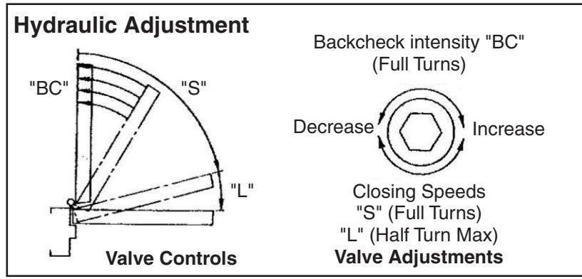
All Valves adjustable by 1/8" (3.18 min) hex key (supplied).
Backcheck controlled by valve on closer and closest to the hinge edge of the door. (Never close BC valve completely). Should backcheck be found extremely early in the opening cycle, rotate the valve 1/2 turn (180°) to correct backcheck position.
Closing Speed controlled by valve on closer end closest to the lock edge of the door. Full turns control the sweep speed. After sweep speed is set, up to 1/2 turn (180°) in either direction adjusts the latch speed.
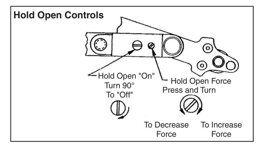
Hold Open option is found at the arm elbow. To select hold open "on" or hold open "off" and to adjust the hold open force ... use screwdriver as illustrated.
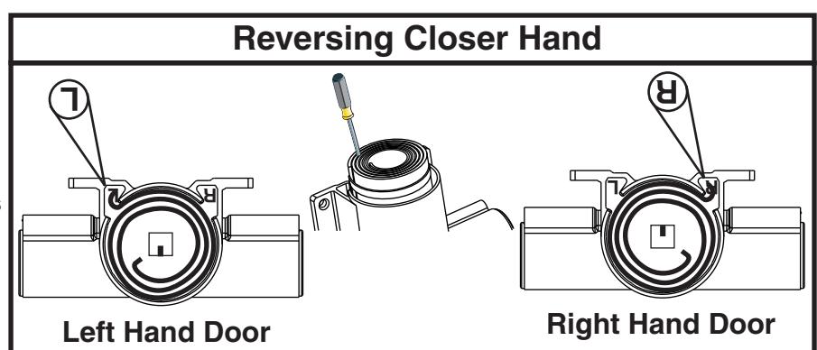
To Reverse Closer Hand
- 1. Remove ratchet and top cover.
- 2. Lift out spring using screwdriver wedged between coils.
- 3. Reverse spring and reassemble to desired hand, as illustrated.
- 4. Rotate shaft 180°, as illustrated.
- 5. Replace top cover and ratchet so that spring inner hook engages into ratchet slot.