Norton Rixson 78-BF Potbelly Series Door Closer B, FHA Hold Open, Regular or Parallel Arm Installation Instructio…_80-9349-0010-020
Open the original PDF document
View PDFInstallation Instructions

Series 78-B/FHA Hold Open Traditional Style Door Closers
ASSA ABLOY
- Read these instructions before proceeding with the installation.
- Make sure that the door opens the full angle desired and latches without any binding action or interference.
-
Select the type of installation from figure 1 below.
- Note: For special applications, a separate door and frame preparation template is packed with these instructions. use this instruction sheet for installation sequence and closer adjustments only.
- Check hand of door, see figure 1 below. Hand of door closer must be the same as hand of door. Door closer is handed but can be easily reversed. SEE PAGE 4 FOR INSTRUCTIONS FOR REVERSING HAND OF CLOSER.
| Type of Installation and Handing of Door Figure | ||||
|---|---|---|---|---|
| Regular Arm Installation | Parallel Arm Installation | |||
|
For installation
on PULL SIDE of Door ONLY |
For installation on PUSH SIDE of Door ONLY | |||
| for Template and Installation | for Template and Installation | |||
| Left Hand Door | Right Hand Door | Left Hand Door | Right Hand Door | |
| Hinge Side | Hinge Side |
Opposite from
Hinge Side |
Opposite from Hinge Side | |
|
Backcheck
Valve Sweep and Latch Valve |
Backcheck
Sweep and Latch Valve |
Backcheck Sweep and Valve Latch Valve | Sweep and Backcheck Latch Valve Valve | |

| 1 | Preparation fo | r Fasteners | Figure 3. | |
|---|---|---|---|---|
| Fasteners |
Door or Frame
Material |
Fastener Preparation | ||
| Standard |
#14 type "A"
S.M. screw |
Wood | 3/16" (4.30mm.) | |
| Aluminum | 7/32" (5.50mm.) | |||
| ¼"-20 machine screw | Metal | drill: #7 (.201"), tap: ¼"-20 | ||
| Optional | Sex nuts and bolts | Hollowmetal |
9/32" (7.00mm.) through;
3/8" (9.50mm.) door face opposite to closer |
|
|
Aluminum
or Wood |
3/8" (9,50mm,) through | |||
| Through bolts and grommet nuts | Atl |
9/32" (7.00mm.) through;
3/8" (9.50mm.) dia. x 3/8" (10mm.) deep door face opposite to closer |
||
-
Norton
- ASSA ABLOY
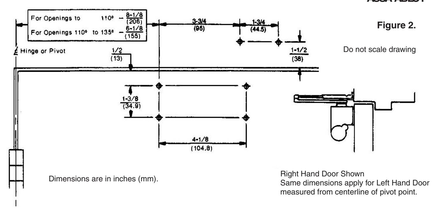
- Using the template at the top of page 2, see figure 2, select the angle of opening desired. Locate and mark for 4 holes on the door for the closer body and 2 holes on the frame for the arm shoe.
- 2. Prepare the door and frame for fasteners using the information from the "Preparation for Fasteners" chart, figure 3 on page 2.
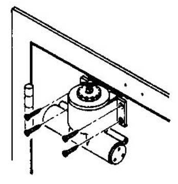
- 3. Install closer body to door as shown.
- 4. Disassemble holder loop assembly from the main arm assembly by loosening set screw.
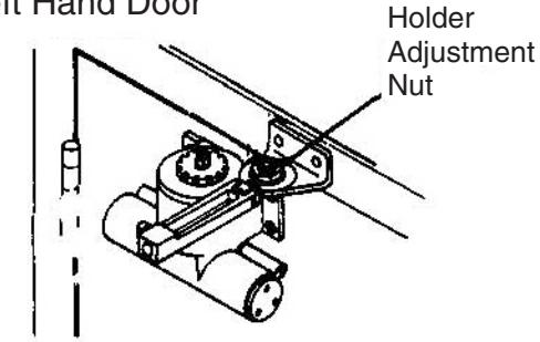
- 5. Fasten holder loop assembly to frame face as shown.
NOTE: Holder Adjustment Nut must be UP for Right Hand Door DOWN for Left Hand Door
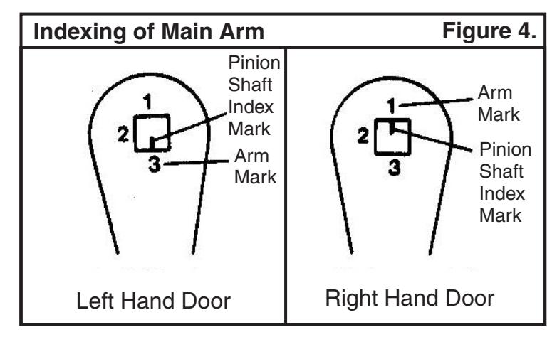
6. Following the main arm indexing illustrations in figure 4, place main arm onto the closer pinion shaft. Install and tighten main arm screw with a 1/2" wrench.
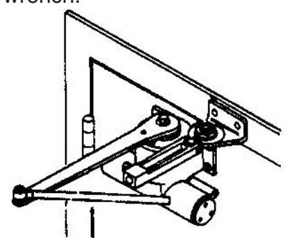
7. Open door slightly and assemble connecting rod into holder loop. Close and latch door. Adjust secondary arm assembly so that the main arm is perpendicular to face of door. Tighten set screw securely.
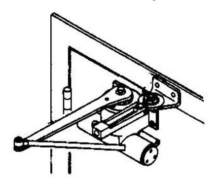
Hold Open Adjustment Open door to angle of hold open desired and tighten holder adjustment nut with wrench supplied.
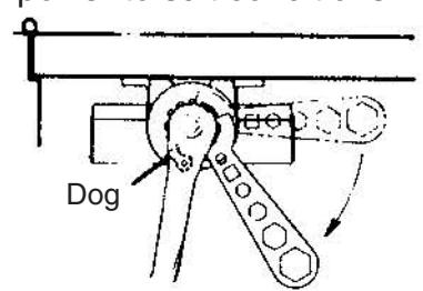
9. Closing Tension - Place wrench (packed with door closer) on ratchet as shown. Swing wrench away from hinge to wind spring between 3 to 10 notches, engage arm dog in ratchet, increase or decrease spring power to suit conditions.
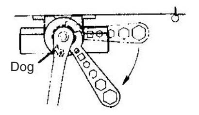
Caution - Underwound spring (less than 3 notches) or overwound spring (more than 10 notches) will cause spring breakage.
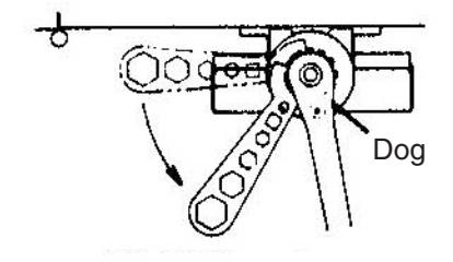
Right Hand Door

Regular Arm Closer Adjustment -
Closing Speed ... Controlled by the regulating valve on the end of the closer closest to the hinge.
Sweep Speed ... Controls the door's speed in the sweep speed range, see illustration. Full 360° clockwise turns decrease the sweep speed. Full 360° counter-clockwise turns increase the sweep speed.
Latch Speed ... Controls the door's speed in the latch speed range, see illustration. A partial turn, up to a maximum of 1/2 turn (180°) in either direction determines the latch speed.
Backcheck ... Controlled by the regulating valve on the end of the closer farthest from the hinge. Backcheck cushions or slows the door opening speed near the end of the opening cycle. Full 360° clockwise turns increases resistance to opening. Full 360° counter-clockwise turns decreases resistance to opening. Note: If backcheck is encountered extremely early in the opening cycle, rotate the valve 1/2 turn (180°) to eliminate early opening resistance.
Caution ... To avoid damage to closer,
never fully close the backcheck regulating
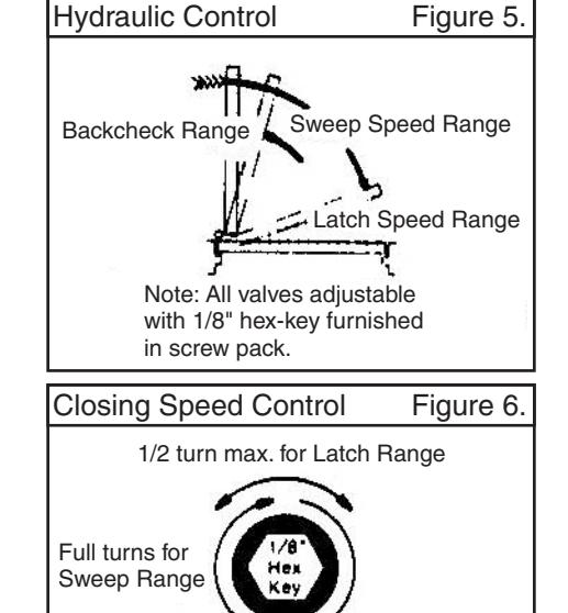
Backcheck Control Figure 7. Full turns for Backcheck Range
Parallel Arm Closer Adjustment -
Closing Speed ... Controlled by the regulating valve on the end of the closer farthest from the hinge.
Sweep Speed ... Controls the door's speed in the sweep speed range, see illustration. Full 360° clockwise turns decrease the sweep speed. Full 360° counter-clockwise turns increase the sweep speed.
Latch Speed ... Controls the door's speed in the latch speed range, see illustration. A partial turn, up to a maximum of 1/2 turn (180°) in either direction determines the latch speed.
Backcheck ... Controlled by the regulating valve on the end of the closer closest to the hinge. Backcheck cushions or slows the door opening speed near the end of the opening cycle. Full 360° clockwise turns increases resistance to opening. Full 360° counter-clockwise turns decreases resistance to opening. Note: If backcheck is encountered extremely early in the opening cycle, rotate the valve 1/2 turn (180°) to eliminate early opening resistance.
Caution ... To avoid damage to closer, never fully close the backcheck regulating valve.
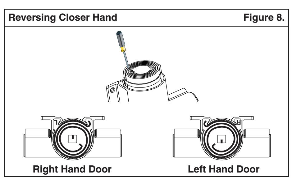
To Reverse Closer Hand
valve
- 1. Remove main arm screw, arm assembly, ratchet, and top cover.
- 2. Lift out spring using screwdriver wedged between coils. (See figure 8)
- 3. Reverse spring and re-assemble to required hand. (See figure 8)
- 4. Rotate shaft to required hand. (See figure 8)
- 5. Replace cover and insert ratchet, lining up slot with inner hook on spring.

| Preparation fo | r Fasteners | Figure 10. | ||
|---|---|---|---|---|
| 000000000000000000000000000000000000000 | Fasteners |
Door or Frame
Material |
Fastener Preparation | |
| Standard |
#14 type "A"
S.M. screw |
Aluminum | 7/32" (5.50mm.) | |
| Wood | 3/16" (4.30mm.) | |||
| %"-20 machine screw | Metal | drill: #7 (.201"), tap: ¼"-20 | ||
| Optional | Sex nuts and boits | Hollowmetal |
9/32" (7.00mm.) through;
3/8" (9.50mm.) door face opposite to closer |
|
|
Aluminum
or Wood |
3/8" (9.50mm,) through | |||
| Through bolts and grommet nuts | Ail |
9/32" (7.00mm.) through;
3/8" (9,50mm.) dia. x 3/8" (10mm.) deep door face opposite to closer |
||
Installation Sequence
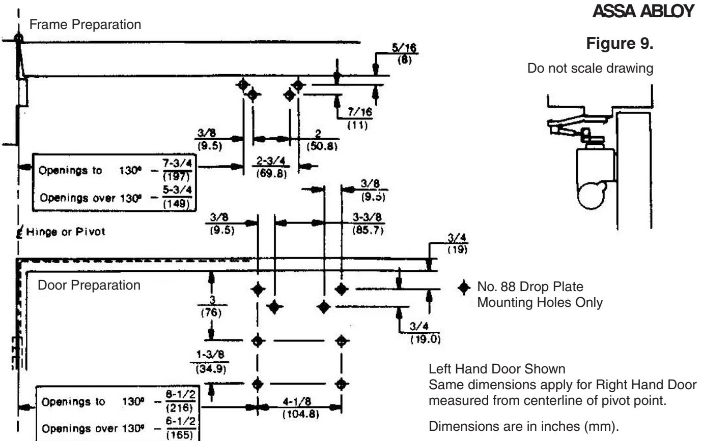
- Using the template at the top of page 5, see figure 9, select the angle of opening desired. Locate and mark for 4 holes on the door for either the closer body or #88 drop plate and 4 holes on the frame for the soffit plate.
- 2. Prepare the door and frame for fasteners using the information from the "Preparation for Fasteners" chart, figure 10 on page 5.
- 3. Install closer body to door as shown. If a backplate is used, mount it first, then fasten the closer to the backplate.
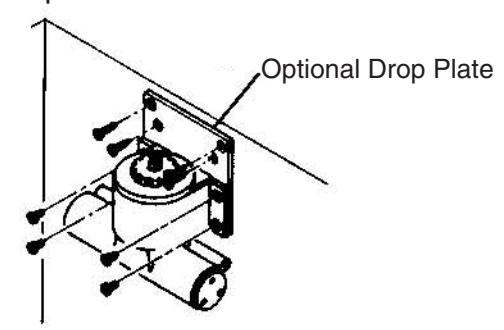
- 4. Disassemble holder loop assembly from the main arm assembly by loosening set screw.
- 5. Fasten soffit plate to frame soffit with 4 mounting screws.
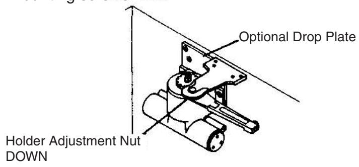
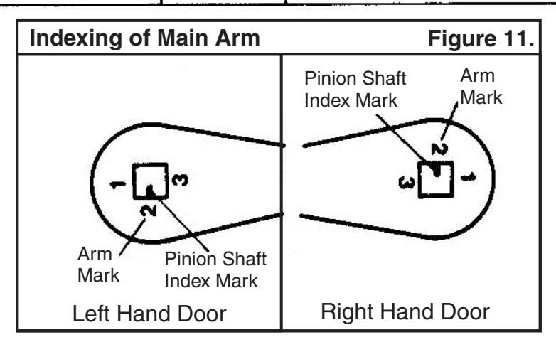
6. Following the main arm indexing illustrations in figure 11, place main arm onto the closer pinion shaft. Install and tighten main arm screw with a 1/2" wrench.
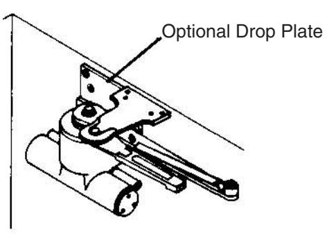
7. Open door slightly and assemble connecting rod into holder loop. Close and latch door. Adjust secondary arm assembly so that the main arm is approximately 2° from parallel with face of door. Tighten set screw securely.
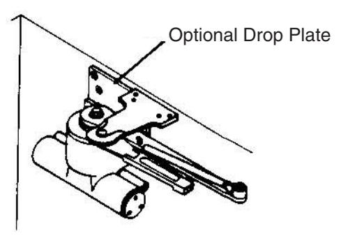
8. Hold Open Adjustment Open door to angle of hold open desired and tighten holder adjustment nut with wrench supplied.
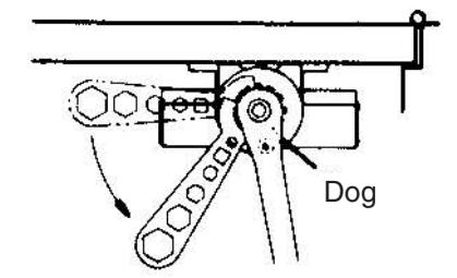
9. Closing Tension - Place wrench (packed with door closer) on ratchet as shown. Swing wrench toward hinge to wind spring between 3 to 10 notches, engage arm dog in ratchet, increase or decrease spring power to suit conditions.
Left Hand Door
Right Hand Door
Caution - Underwound spring (less than 3 notches) or overwound spring (more than 10 notches) will cause spring breakage.