Norton Rixson 7500 Series Door Closer Tri-Style (Regular, Parallel or Top Jamb) Non-Hold Open Installation Instr…_80-9377-1201-020
Open the original PDF document
View PDF7500
Non Handed Door Closer
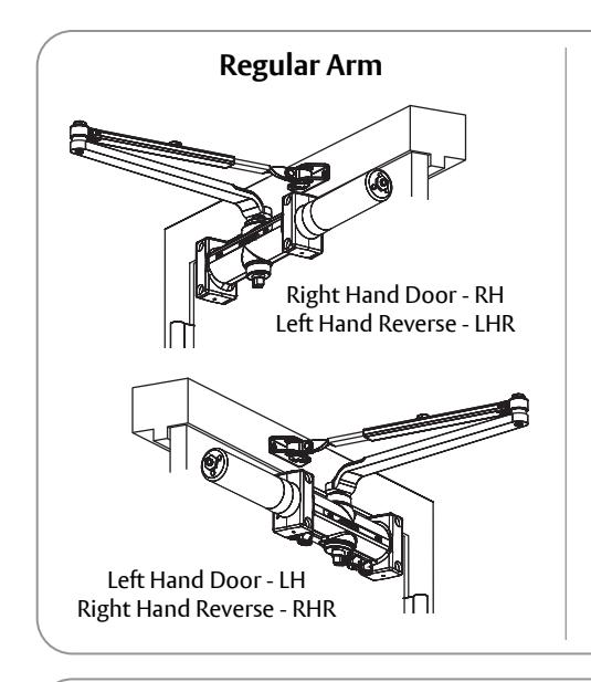
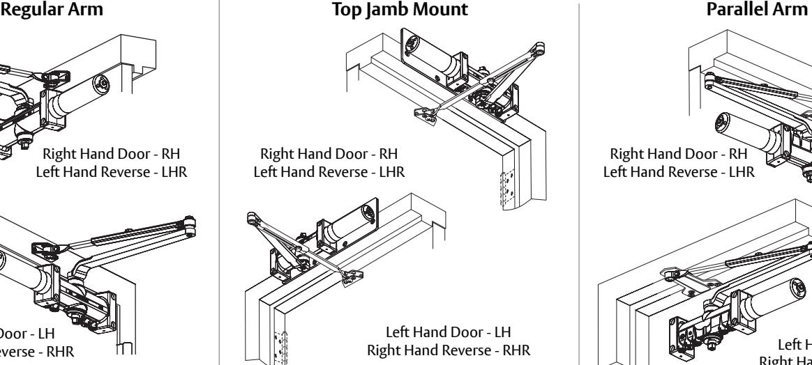
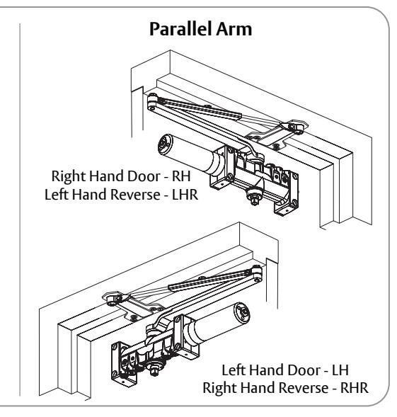
Regular Arm Top Jamb Mount Parallel Arm With or without DA suffix (delayed action) With or without M suffix (metal cover)
Non Hold Open Arm Models
Adjustable (Sizes 1-6)
7500 J7500 JL7500 P7500


WARNING
This product can expose you to lead which is known to the state of California to cause cancer and birth defects or other reproductive harm. For more information go to www.P65warnings.ca.gov.
Ce produit peut vous exposer au plomb qui, dans l'état de la Californie, est reconnu pour causer le cancer, des anomalies congénitales ou d'autres problèmes de reproduction. Pour plus d'informations, visitez: www.P65warnings.ca.gov.
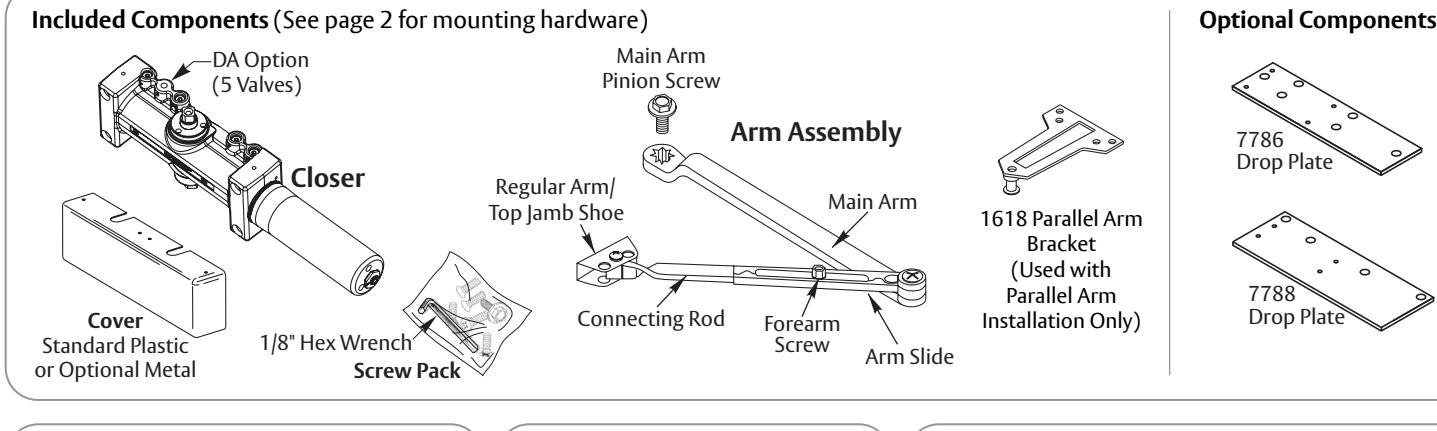
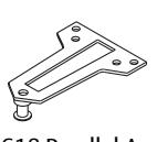
1618 Parallel Arm Bracket (Used with Parallel Arm Installation Only)
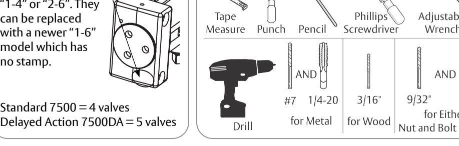
Tools Needed
HAND OF LEFT HAND DOOR RIGHT HAND DOOR Right Hand Reverse Left Hand Reverse To Determine Your Hand of Door: To Identify Your Model:
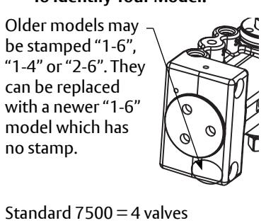

7500 Non Hold Open Closer
ATTENTION:
An incorrectly installed or improperly adjusted door closer can cause property damage or personal injury. These installation instructions should be followed to avoid the possibility of misapplication or misadjustment.
- For special applications, a separate door and frame preparation template is packed with these instructions. Use these instructions for installation sequence and closer adjustments only.
- 7500 Series closing force is adjustable from 1-6 as outlined in ANSI Standard A156.4. When closer is adjusted to conform to ADA reduced opening force requirements (5 lbs max.) for interior doors, it may not have adequate closing force to reliably close and latch door. Charted power adjustments in instructions are recommended where possible, to ensure proper door control.
- Doors should be hung on ball bearing or anti-friction hinges.
- A separate door stop is recommended.
- Always consult door/frame manufacturer for fastener compatibility.
- Door and frame must be properly reinforced.
- Adjust closing time speed between 3 7 seconds from 90° 0°.
- These door closers should NOT be installed on exposed side (weather side) of exterior doors.
- Dimensions are given in inches (millimeters).
| Mounting Hardware | Door or Frame | Drill | |
|---|---|---|---|
| Arm Shoe or Optional PA Bracket: | Wood | 3/16" (4.76mm) | |
| 1/4-14 x 1-1/2 Flat Head Self Drilling Screw | Aluminum or Metal | no drill required | |
| Closer: Wood | 3/16" (4.76mm) | ||
| 1/4-14 x 3 Flat Head Self Drilling Screw | Aluminum or Metal | no drill required | |
| Arm Shoe or Optional PA Bracket: 1/4-20 x 1-1/2 Oval Head Machine Screw | Metal | Drill #7 (.201 dia. or 5.10mm) | |
|
Closer:
1/4-20 x 3 Flat Head Machine Screw |
Metal | Tap 1/4-20 | |
| Timi |
Arm to Optional PA Bracket:
1/4-20 x 1/2 Oval Head Machine Screw |
N/A | N/A |
| Closer or Arm Shoe: Sleeve Nut and Bolt (SNB) | Hollow Metal |
9/32" (7.00mm) thru
3/8" (9.50mm) door face opposite to closer |
|
| (optional) | Aluminum or Wood | 3/8" (9.50mm) thru | |
| Consessed and the control of the control of the control of the control of the control of the control of the control of the control of the control of the control of the control of the control of the control of the control of the control of the control of the control of the control of the control of the control of the control of the control of the control of the control of the control of the control of the control of the control of the control of the control of the control of the control of the control of the control of the control of the control of the control of the control of the control of the control of the control of the control of the control of the control of the control of the control of the control of the control of the control of the control of the control of the control of the control of the control of the control of the control of the control of the control of the control of the control of the control of the control of the control of the control of the control of the control of the control of the control of the control of the control of the control of the control of the control of the control of the control of the control of the control of the control of the control of the control of the control of the control of the control of the control of the control of the control of the control of the control of the control of the control of the control of the control of the control of the control of the control of the control of the control of the control of the control of the control of the control of the control of the control of the control of the control of the control of the control of the control of the control of the control of the control of the control of the control of the control of the control of the control of the control of the control of the control of the control of the control of the control of the control of the control of the control of the control of the control of the control of the control of the control of the control of the control of the control of the control of the control of the con |
Closer or Arm Shoe:
Thru Bolt and Grommet Nut (TBGN) (optional) |
All |
9/32" (7.00mm) thru
3/8" (9.50mm) dia. x 3/8" (9.500mm) deep, door face opposite to closer |
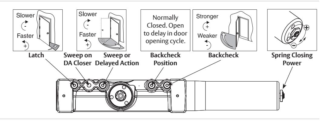
Closer Adjustments

Use provided hex wrench to turn valves. NEVER force valves out of closer. NEVER completely close backcheck valve.
Door must be open to adjust spring closing power. Refer to specific charts on installation pages. Do not use a power drill. Warranty will be void.

1. Prepare door and frame.
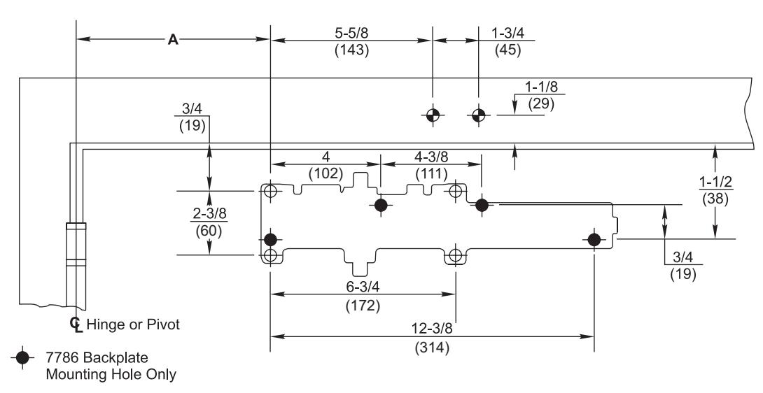
| 1 | ||
|---|---|---|
| Dim A | ||
| Opening | inches (mm) | |
| To 100° | 7-5/8 (194) | |
| 101° to 120° | 6-5/8 (168) | |
| 121° to 150° | 4-5/8 (117) | |
| 151° to 180° | 4-1/8 (105) |
| Power Adjustment Chart | |||
|---|---|---|---|
|
Maximum
Interior Door Size inches (mm) |
Maximum
Exterior Door Size inches (mm) |
Turns
from Zero |
|
| 32 (813) | 28 (711) | 5 | |
| 36 (914) | 34 (864) | 8-1/2 | |
| 42 (1067) | 38 (965) | 11 | |
| 52 (1321) | 42 (1067) | 13-1/2 | |
| 60 (1524) | 48 (1219) | 16-1/2 | |
2. Mount optional backplate and/or closer to door.
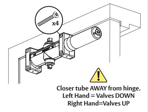
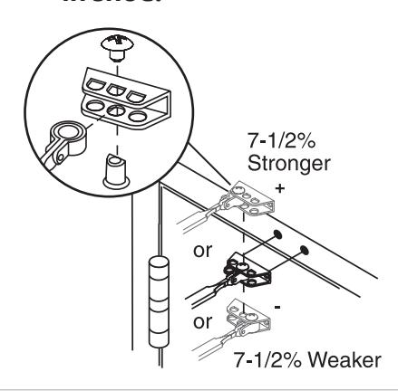
3a. Choose arm placement in shoe.
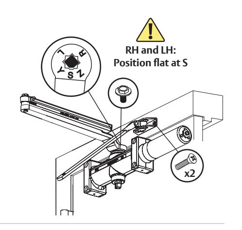
3b. Install separate arms.
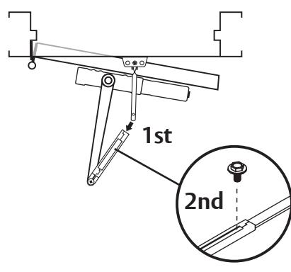
4. Connect arms and install forearm screw.
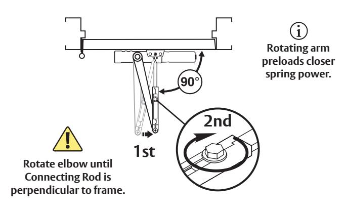
5. Preload spring and tighten forearm screw.
You've installed the 7500 Non Hold Open Closer - Regular Arm.
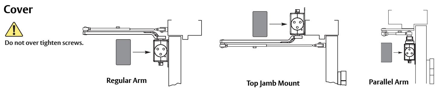
Go to page 2 for closer adjustments and cover installation.
7500 Top Jamb Mount Installation (Right Hand Shown)
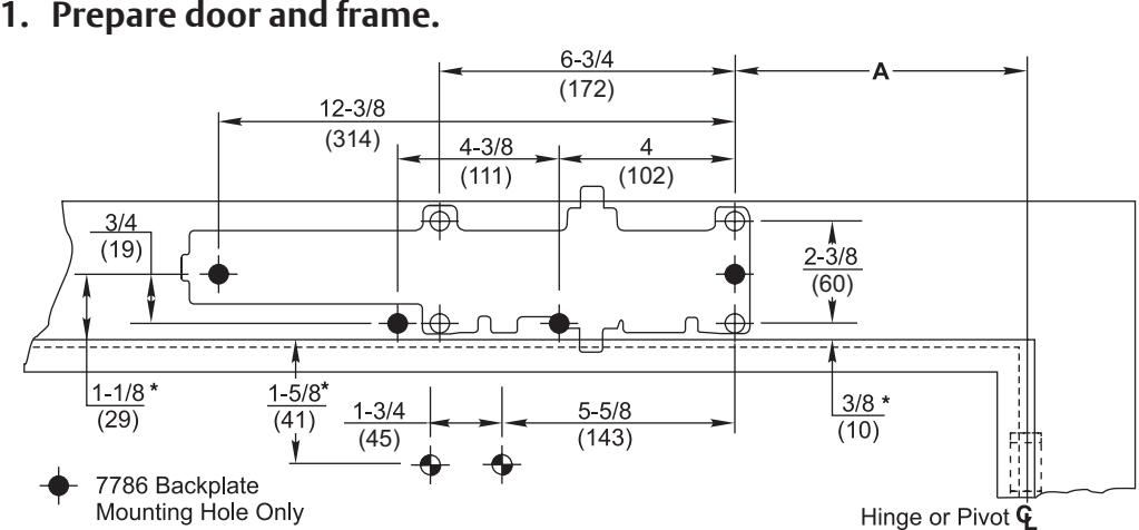
* Always use frame or transom rabbet as reference plane, not bottom of stop.
| Reveal Range | Door Swing | Model | Complete Arm | Adjusting Rod |
| Under 3" (76) | 180° | 7500 | 7701-1 | 7701-11 |
| 3" to 4-1/4" (76 to 108) | 180° | J7500 | 7701-1A | 7701-11A |
| 4-1/4" to 6-7/8" (108 to 175) | 150° | J7500 | 7701-1A | 7701-11A |
| 4-1/4" to 6-7/8" (108 to 175) | 180° | JI7500 | 7701-1B | 7701-11B |
| Dimension A | ||
|---|---|---|
| Opening | inches (mm) | |
| To 100° | 7-5/8 (194) | |
| 101° to 120° | 6-5/8 (168) | |
| 121° to 150° | 4-5/8 (117) | |
| 151° to 180° | 4-1/8 (105) | |
| Power Adjustment Chart | |||
|---|---|---|---|
|
Maximum
Interior Door Size inches (mm) |
Maximum
Exterior Door Size inches (mm) |
Turns
from Zero |
|
| 32 (813) | 28 (711) | 5 | |
| 36 (914) | 34 (864) | 8-1/2 | |
| 42 (1067) | 38 (965) | 11 | |
| 52 (1321) | 42 (1067) | 13-1/2 | |
| 60 (1524) | 48 (1219) | 16-1/2 | |
2. Mount optional backplate and/or closer to frame.
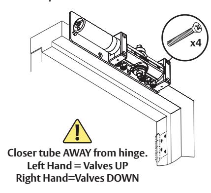
3b. Install separate arms. 3a. Choose arm placement
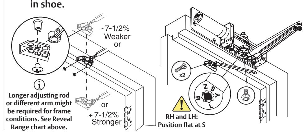
4. Connect arms and install forearm screw.
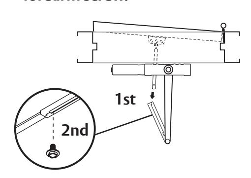
5. Preload spring and tighten forearm screw.
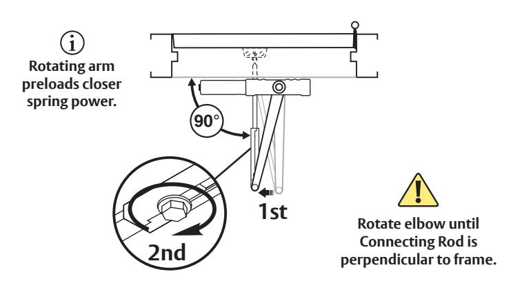
You've now installed the 7500 Non Hold Open Closer - Top Jamb Mount.
Go to page 2 for closer adjustments and cover installation.

1. Prepare door and frame.
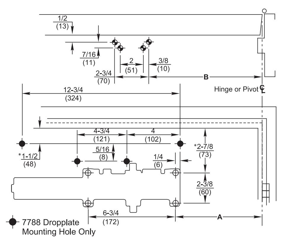
| Dimension A | Dimension B | |
|---|---|---|
| Opening | inches(mm) | inches (mm) |
| To 100° | 8-3/4 (222) | 9-1/4 (235) |
| 101° to 130° | 7-1/4 (184) | 7-3/4 (197) |
| 131° to 150° | 6-1/4 (159) | 6-3/4 (171) |
| 151° to 180° | 5-1/4 (133) | 5-3/4 (146) |
| Power Adjustment Chart | |||
|---|---|---|---|
|
Maximum
Interior Door Size inches (mm) |
Maximum
Exterior Door Size inches (mm) |
Turns
from Zero |
|
| 30 (762) | 26 (660) | 7 | |
| 34 (864) | 30 (762) | 9 | |
| 38 (965) | 36 (914) | 12-1/2 | |
| 48 (1219) | 42 (1067) | 14-1/2 | |
| 54 (1372) | 48 (1219) | 16-1/2 | |
| NOTE: Maximum of 16-1/2 turns (360°) of Power Adjustment Nut. | |||
* Assuming 5/8" (16) stop height
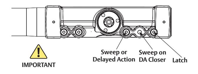
2. Close latch and sweep valves. 3. Install soffit plate and mount optional backplate and/or closer.
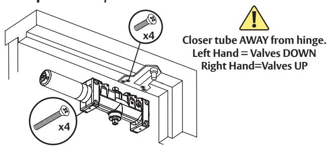
4. Remove arm shoe and install forearm to plate.
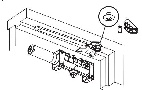
5. Place main arm on closer spindle and rotate approximately 50 degrees.
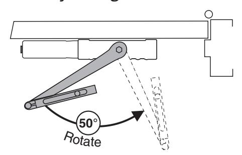

7500 Parallel Arm Installation (Right Hand Shown) continued
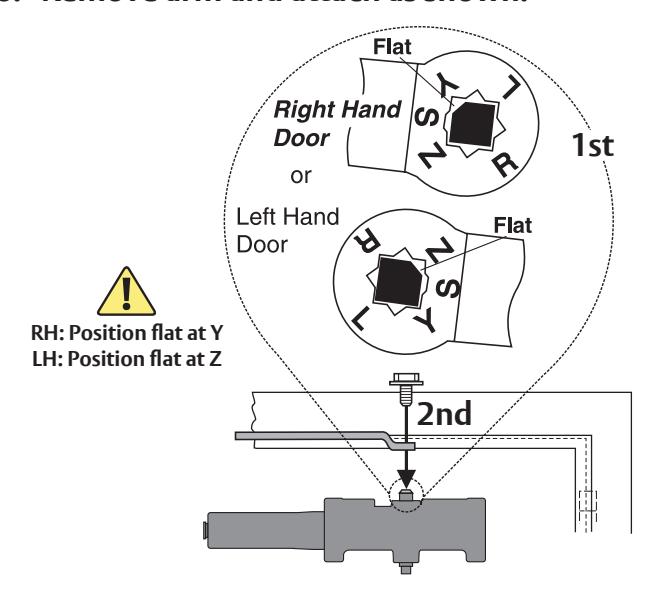
6. Remove arm and attach as shown.
7. Open latch and sweep valves.
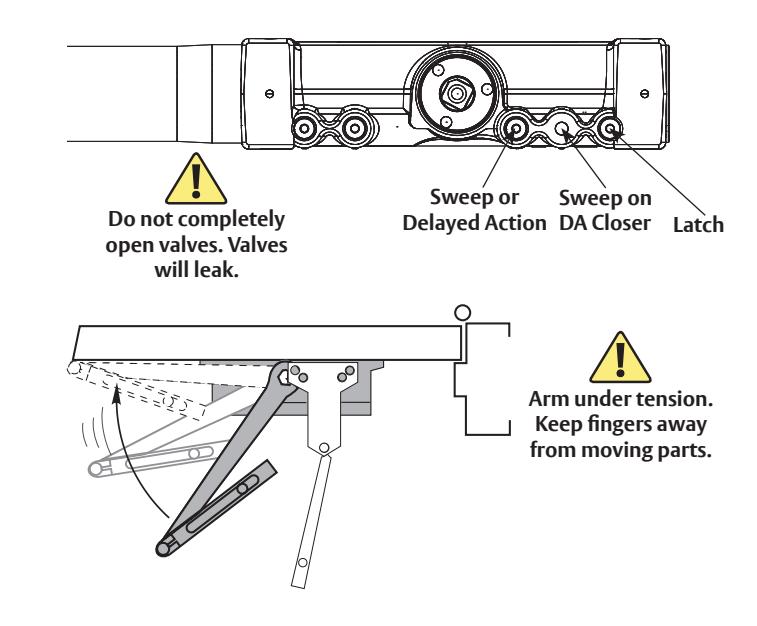
8. Connect arms and install forearm screw.
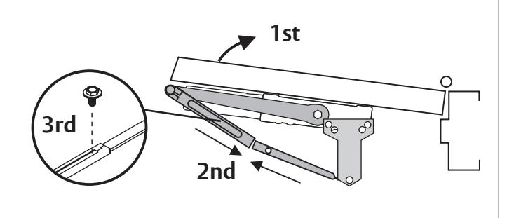
9. Preload spring and tighten forearm screw.
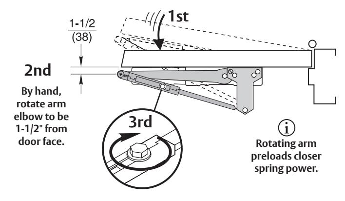
You've now installed the 7500 Non Hold Open Closer - Parallel Arm.
Go to page 2 for closer adjustments and cover installation.
Technical Product Support: Monroe, NC 28112 USA Phone: 877.974.2255 ext: 2 Techsupport.NortonRixson@assaabloy.com NortonRixson.com