Norton Rixson 7500 Series Door Closer, CLP7500R, CLSP7700R, CloserPlus Ramp Hold Open Arm Installation Instructi…_80-9377-2208-020
Open the original PDF document
View PDFCloserPlus® Ramp™ (CLP-R) Arm 7500 Door Closer, Hold Open
Standard, Narrow Frame and Flush Partition Installation Instructions


WARNING
This product can expose you to lead which is known to the state of California to cause cancer and birth defects or other reproductive harm. For more information go to www.P65warnings.ca.gov.
Additional Closer Options:
- "DA" indicates Delayed Action closing
- "R" indicates Ramp Hold-Open function, not handed
Optional Accessories:
- 7788 Drop Plate
- 2019L, 6890, 6891 Soffit Plate Accessories
| Model Numbers Included: | ||||||||
|---|---|---|---|---|---|---|---|---|
| Series Function Sizing | ||||||||
| CLP7500R HO 1-6 | ||||||||
| CLP770XR HO 2 THRU 6 | ||||||||
| "Y" Designates closer size 2 3 4 5 or 6 | ||||||||
An incorrectly installed or improperly adjusted door closer can cause property damage or personal injury These instructions should be followed to avoid the possibility of misapplication or misadiustment.
NOTE: For special applications a separate door and frame preparation template is packed with these instructions. In those cases. use this instruction sheet for installation sequence and closer adjustments only.
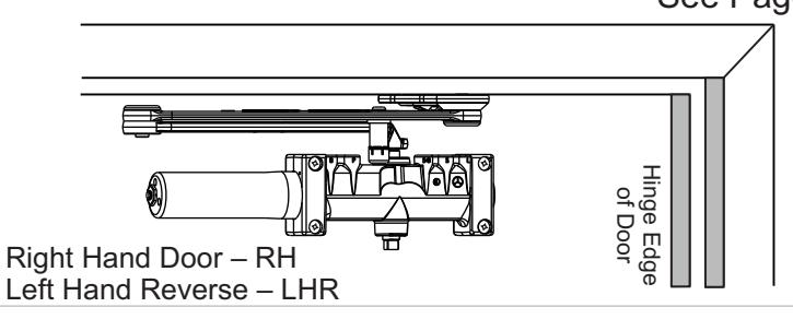
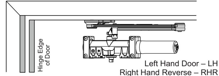
Standard Frame Installation
Closer mounts on opposite to hinge (push) side of door. See Pages 3 and 4
Narrow Frame Installation
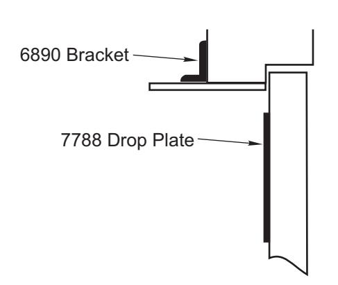
Closer mounts on opposite to hinge (push) side of door. 6890 and 6891 accessories required for this application (supplied separately).
See Pages 3 and 4
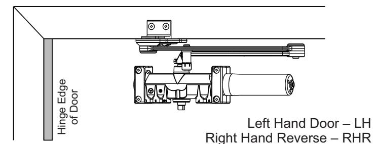
Right Hand Reverse - RHR
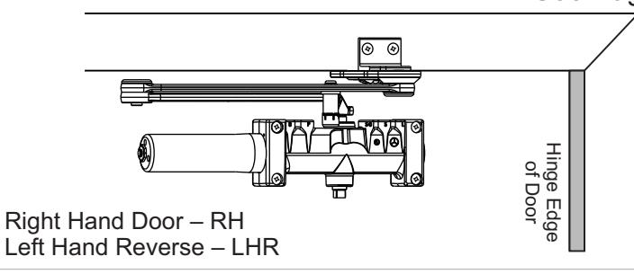
Flush Partition Installation
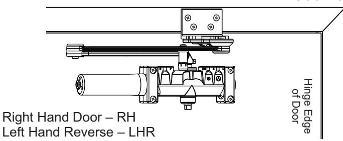
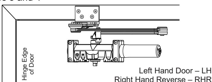
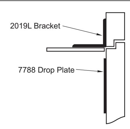
Closer mounts on opposite to hinge (push) side of door. 2019L accessory required for this application (supplied separately).
See Pages 3 and 4
Copyright © 2013-2014, 2022, ASSA ABLOY Accessories and Door Controls Group, Inc. All rights reserved. Reproduction in whole or in part without the express written permission of ASSA ABLOY Accessories and Door Controls Group, Inc. is prohibited. 80-9377-2208-020 Rev 3 03/22

CloserPlus<sup>®</sup> Ramp<sup>™</sup> (CLP-R) Arm 7500 Series
Components
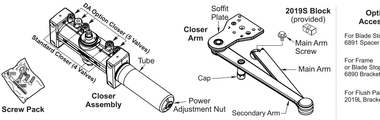
Optional Accessories
For Blade Stop

or Blade Stop 6890 Bracket

For Flush Partition 2019L Bracket
Cover Options

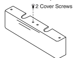
Metal Cover (Optional)
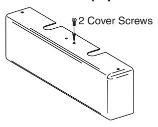
| Preparation for Fasteners | ||||||
|---|---|---|---|---|---|---|
| Fasteners | Door or Frame | Drill-Sizes | ||||
| Solf Drilling Sorow | Aluminum or Metal | No drill required | ||||
| Standard | Self-Drilling Screw | Wood |
3/16" (4.80 mm)
Pilot hole required |
ו | ||
| 1/4" - 20 machine screw | Metal |
Drill: #7 (0.201" dia.)(5mm)
Tap: 1/4" - 20 |
||||
| Optional | Sleeve nuts and bolts |
Hollow
Metal |
9/32" (7 mm) thru;
3/8" (9.5 mm) door face opposite to closer |
|||
| Aluminum or Wood | 3/8" (9.5 mm) through | |||||
| Through-bolts and grommet-nuts | All |
9/32" (7 mm) thru;
3/8" (9.5 mm) dia. x 3/8" (9.5 mm) deep on door opposite to closer |
||||
Note: Wood doors MUST be pre-drilled when using Self-Drilling Screws.
CloserPlus® Ramp™ (CLP-R) Arm 7500 Series

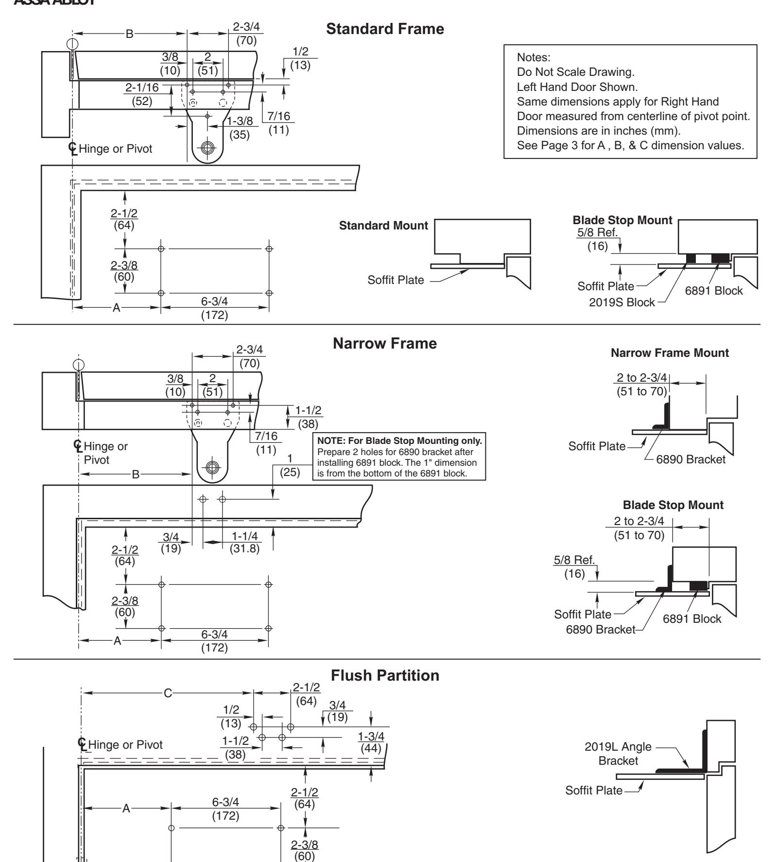
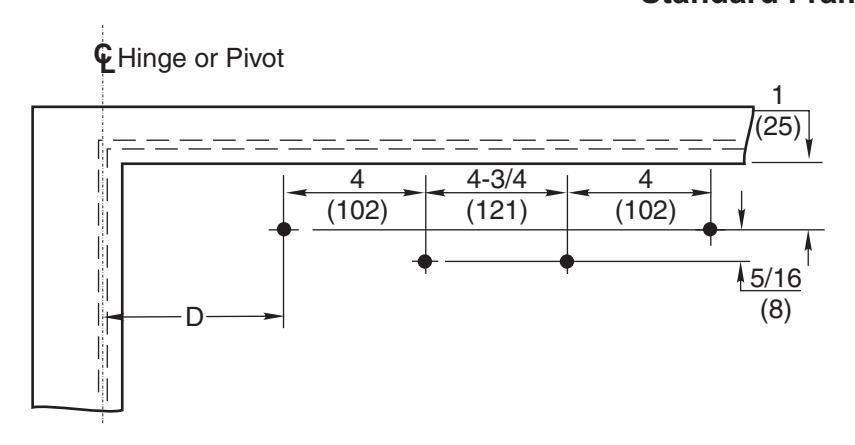
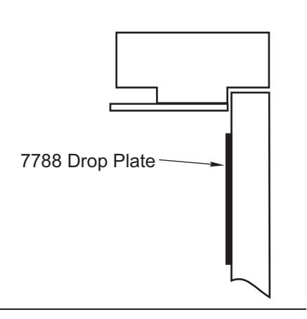
- Select angle of opening and use dimensions shown on Page 4 and Dimension Chart below to locate 4 holes on door for closer body (or 4 holes for 7788 Drop Plate, Page 6, only if required) and 5 holes on stop/rabbet for Soffit Plate (or 4 holes on frame transom for 2019L bracket, only if required). For applications not covered in these instructions, a separate template will be required.
- Prepare door and frame for fasteners using "Preparation for Fasteners" chart on Page 2.
- Install closer body to door, or 7788 Drop Plate, with power adjustment shaft away from hinge edge of door and adjustment valves:
Down for Left Hand Up for Right Hand
Mount 7788 Drop Plate to door ... only if used (see Page 6).
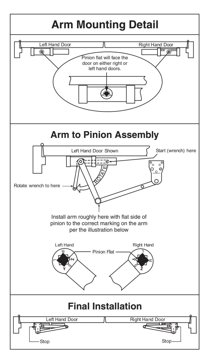
Install Main Arm: Close valves ('S/D' or 'S') and 'L', then using a wrench, rotate the pinion shaft at least 50° to permit alignment of the Pinion Flat with the proper arm mark:
'Z' for Left Hand 'Y' for Right Hand
See below right for illustrations of this procedure.
| Power Adjustment Chart | ||||||||
|---|---|---|---|---|---|---|---|---|
| Dim | * | MAXIMUM DOOR SIZE | ||||||
| DOOR |
32"
(0.81m) |
36"
(0.9 m) |
42"
(1.1 m) |
48"
(1.2 m) |
||||
| INT | CLP7500 |
EE TURNS
USTMENT |
0 | 3 | 5 | 8 | ||
| EXT | CLP/500 | 4 | 6 | 8 | 12 | |||
| INT | CLP7700 |
FULL 360 DEC
OF POWER A SHA |
0 | 2 | 5 | 8 | ||
| EXT | CLP7700 |
FULL
OF PC |
2 | 5 | 8 | 11 | ||
*17 - 360°, MAXIMUM AVAILABLE
| Installation Dimensions Chart | |||||||||
|---|---|---|---|---|---|---|---|---|---|
| Dim |
Up to
90° |
90°-
95° |
95°-
100° |
100°-
105° |
105°-
110° |
110°-
115° |
|||
| A in./(mm) |
10-1/8
(257) |
9-1/4
(235) |
8-5/8
(219) |
7-7/8
(200) |
7-3/8
(187) |
6-3/4
(171) |
|||
|
CLP7500/
CLP770X |
B in./(mm) |
10-5/8
(270) |
9-3/4
(248) |
9-1/8
(232) |
8-3/8
(213) |
7-7/8
(200) |
7-1/4
(184) |
||
| C in./(mm) |
10-3/4
(273) |
9-7/8
(251) |
9-1/4
(235) |
8-1/2
(216) |
8
(203) |
7-3/8
(187) |
|||
- Reopen valves ('S/D' or 'S') and 'L', that were closed in previous step.
- With door closed, align soffit plate with holes in frame and fasten to frame with screws. Use 2019S and/or 6891 spacer blocks or 6890 reinforcing bracket as required.
- 7500 Series Closers only: Closer is shipped from factory set at mid-range. Using "Power Adjustment" chart below, rotate power adjustment shaft with 1/8" allen wrench supplied: Turn CLOCKWISE to increase power. Turn COUNTER-CLOCKWISE to decrease power. See Page 7 for the illustration of this step.
- Make adjustments to closer before installing cover. See Page 7 for closer adjustment instructions. CAUTION: Do Not back valves out of closer body or a fluid leak will result.
- Install cover.

CloserPlus<sup>®</sup> Ramp<sup>™</sup> (CLP-R) Arm 7500 Series
® CloserPlus Ramp™ (CLP-R) Arm 7500 Series

Standard Frame 7788 Drop Plate Mounting Holes
Narrow Frame
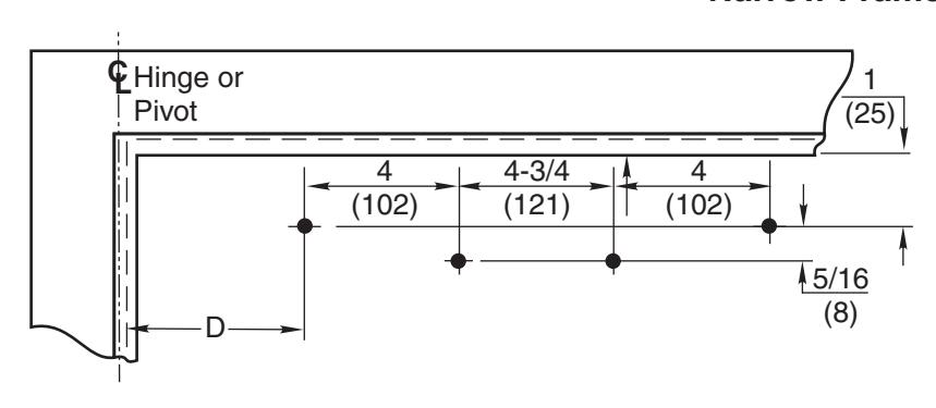
Flush Partition CL Hinge or Pivot 4 (102) 4-3/4 (121) 5/16 (8) 1 (25) 4 (102) D
Notes:
Left Hand Door Shown.
Same dimensions apply for Right Hand Door measured from centerline of pivot point.
Dimensions are in inches (mm).
See Chart below for D dimension values.
| Installation Dimensions Chart | |||||||
|---|---|---|---|---|---|---|---|
The ASSA ABLOY Group is the global leader in access solutions. Every day we help people feel safe, secure and experience a more open world.

Adjustments
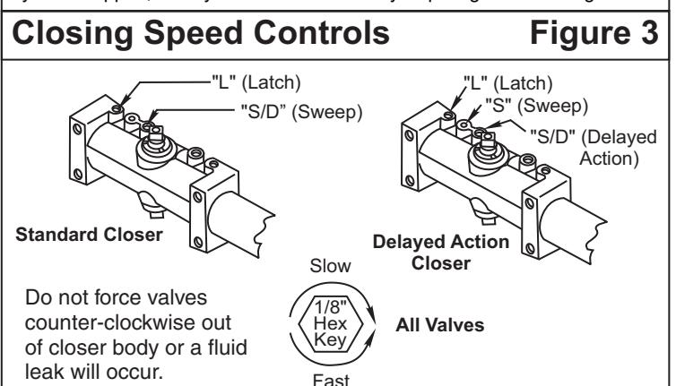
Control Valve Adjustments (See Figure 3.)
Closing Speed Controls (Figure 2A or 2B and 3.)
- · Valve "S" Controls Sweep Range.
- Valve "L" Controls Latch Range.
Closing Power Control Figure 1 For 7500 Series Only Set closer to desired size. For recommended sizes, refer to the Power "Spring Power Adjustment Chart on page 3. Adjustment Nut" Install closer per instructions with proper pre-load applied to arm then adjust spring power. Power adjustment will not work properly if closer spring is not pre-loaded. To increase power, use 11/16" wrench to turn power adjustment nut clockwise. To decrease power, turn nut counter clockwise.
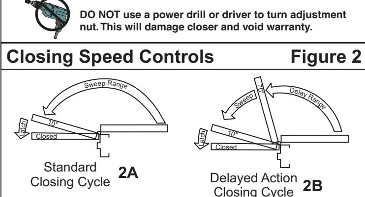
Adjust Closing Speed Time to between 3-7 seconds from 90°. Use of door by handicapped, elderly or small children may require greater closing time.
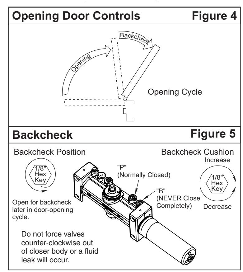
Opening Door Control (Figure 4 and 5.)
- Backcheck ("B") valve controls the hydraulic resistance to door opening. NEVER close this valve completely – it is not to provide a positive stop.
- Backcheck position ("P") valve controls the door angle where backcheck cushioning starts. Valve normally closed.
Hold-Open Feature
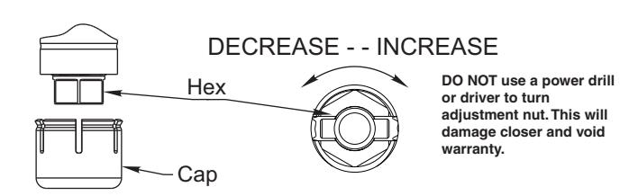
The hold-open mechanism is controlled by the hex nut feature located on the secondary arm underneath cap. Remove cap by pulling straight down. Use a 7/16" wrench to adjust. Turning hex nut feature clockwise will increase hold-open force. Turning hex nut feature counter clockwise will reduce hold-open force. Hold-open mechanism can not be disengaged.
Technical Product Support: Monroe, NC 28112 USA Phone: 877.974.2255 ext: 2
Techsupport.NortonRixson@assaabloy.com
NortonRixson.com