Norton Rixson 700 Wave to Open Switch Installation Instructions_80-9375-0001-020
Open the original PDF document
View PDFModel 700 Wave to Open Switch
Standard Double or Single Gang Installation Instructions

Specifications:
Input Voltage: 12V to24VDC
SPDT Contact Rating: 2A @30VAC/VDC Sensor Detection Range: Up to 4" (101mm)
Operating Temperature: -13° F to 131°F (-25°C to 55°C) Current Draw: 50mA @12VDC, 65mA @24VDC
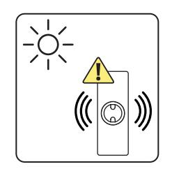
Bright light like direct sunlight can interfere with the Wave To Open signal.
Norton Radio Frequency Transmitter (P/N 548) is sold separately.
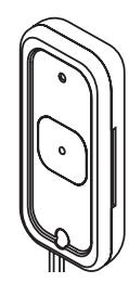
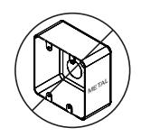
Metal enclosures can reduce signal strength and cause an intermittent or reduced signal reception when using a radio frequency transmitter. To ensure proper function, do not use metal conduit housing.

WARNING
This product can expose you to lead which is known to the state of California to cause cancer and birth defects or other reproductive harm. For more information go to www.P65warnings.ca.gov.

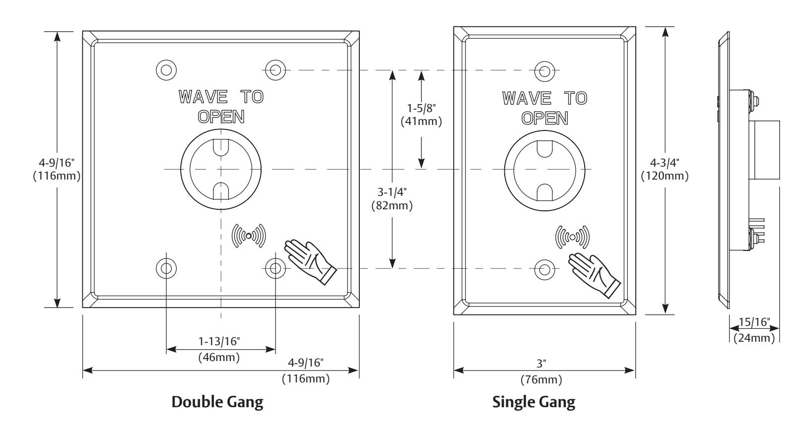
Specifications:
Input Voltage: 12V to24VDC
SPDT Contact Rating: 2A @30VAC/VDC Sensor Detection Range: Up to 4" (101mm)
Operating Temperature: -13° F to 131°F (-25°C to 55°C)
Current Draw: 50mA @12VDC, 65mA @24VDC
Operation:
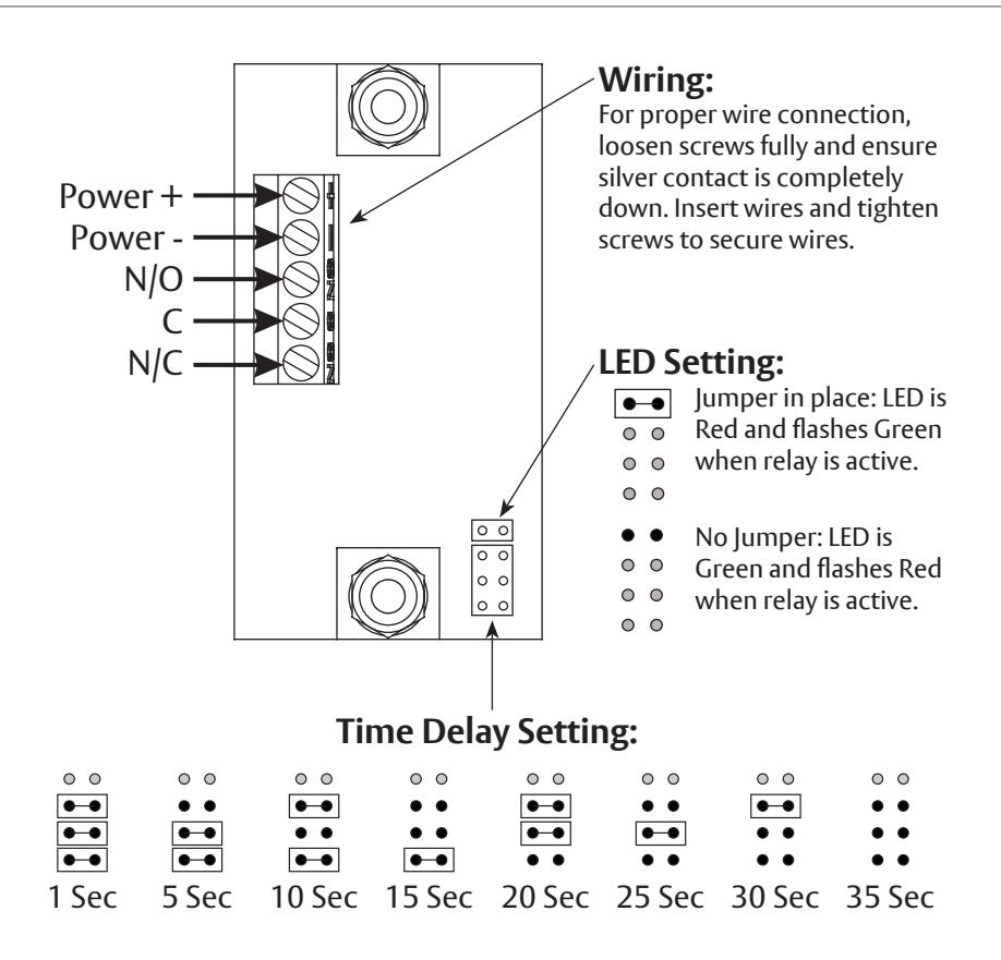
Two Modes: Standby (LED Red) Operating (LED flashing Green)
To operate switch, make a slow waving motion with hand in front of plate within 4" (101mm).
When hand movement is detected or manual override button is pressed, a tone will sound and LED circle will flash to indicate relay has been activated.
Relay will activate for amount of time as set by time delay jumpers. Manual override button can be used to activate relay at any time.
Model 700 Wave to Open Switch
Installation
Install Plastic Conduit Housing
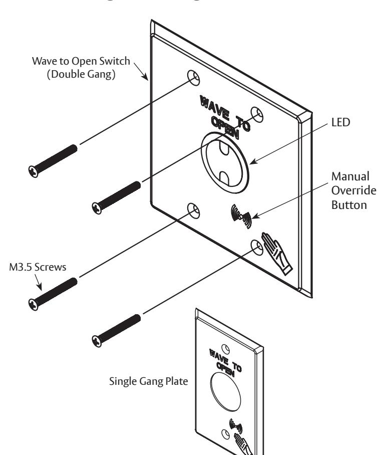
NOTE: See "Changing Plate" instructions on page 5 if using single gang housing.
- 1. Measure and mark wall with horizontal centerline of switch between 34" - 48" (86.4cm - 121.9cm) from floor. (Fig 1)
- 2. If agency with jurisdiction requires, secure wire conduit (supplied by others) to back of housing and feed wires through. (Fig 2)
- 3. Strip sheath from each wire end exposing 5/16" (7.9) to prepare wires for connection. (Fig 2)
- 4. Prepare wall for housing using typical methods for wall material.
- 5. Install housing in wall using fasteners supplied by others.

Install Switch

1. Set LED and Time Delay Settings as desired on Wave to Open switch. See "LED Setting" and "Time Delay Setting", page 2.

- 2. Use small flat head screwdriver to connect 24VDC and activation wiring with terminal block. (Fig 3) See "Wiring", page 2 and appropriate wiring diagram of door operator instructions.
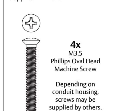
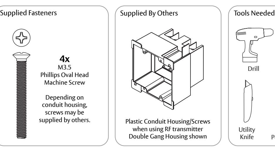
- 3. Attach Wave to Open switch to conduit housing. Conduit housing may require use of screws supplied by others. M3.5 Philips Oval Head Machine screws are provided. (Fig 4)

Verify all wiring is inside conduit housing before switch plate is secured.


Installation of RF Transmitter

When utilizing a radio frequency transmitter:
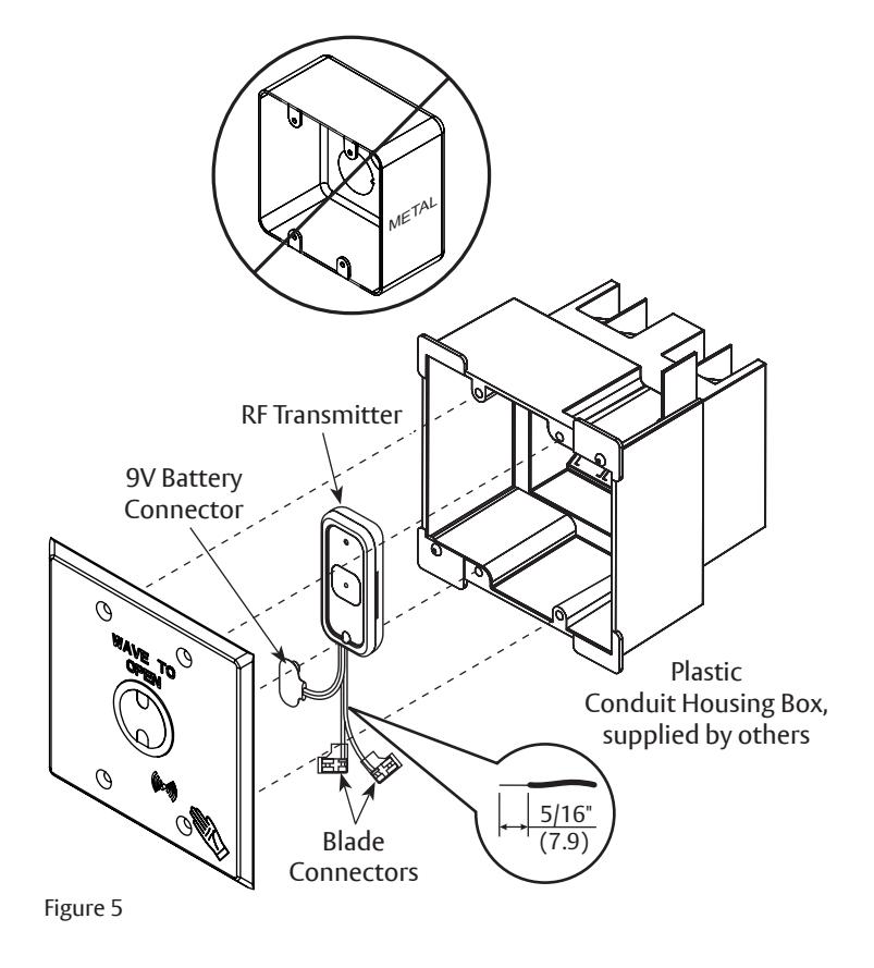
- A plastic conduit housing box is necessary. (Fig 5)
- Metal can reduce signal strength. To ensure proper function, an RF transmitter should not be used when Wave To Open switch is installed in a metal enclosure.
- A 12V to 24VDC power source is ALWAYS needed to power Wave To Open switch. Source can be an operator or a DC transformer.
- 1. Prepare wall and install conduit housing as outlined on page 3.
- 2. Using wire cutters, remove blade connectors from both green and white RF Transmitter wires.

DO NOT cut red and black 9V battery connector wires.
- 3. Strip sheath from each wire end exposing 5/16" (7.9) to prepare wires for connection. (Fig 5)
-
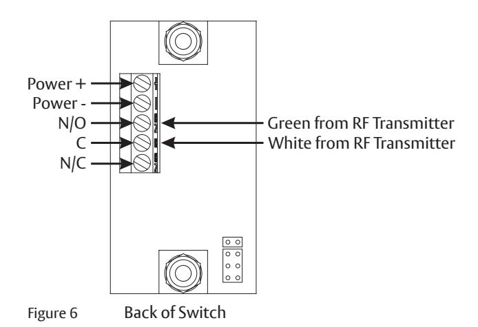
4. Wire RF Transmitter to Switch (Fig 6):
- Green wire to Normally Open (NO)
- White wire to Common (C).
- 5. Install 9V Battery to female battery connector. (Fig 5)
- 6. Install switch as outlined on page 3.

Verify all wiring is inside conduit housing before switch plate is secured.
7. Pair transmitter by activating switch while RF Receiver on door operator is in pairing mode.
The ASSA ABLOY Group is the global leader in access solutions. Every day we help people feel safe, secure and experience a more open world.

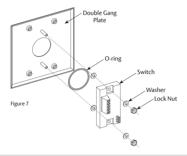
Changing Plate
- 1. Remove lock nut and washer from back of switch.
- 2. Remove switch and O-ring from plate.
- 3. Reassemble using replacement plate.