Norton Rixson 6000 Series Operator, D6001DE-L Double Door Double Egress Left Installation Instructions_80-9360-1037-020
Open the original PDF document
View PDFD6001DE-L Series
Double Egress Power Operator Installation Instructions



WARNING
This product can expose you to lead which is known to the state of California to cause cancer and birth defects or other reproductive harm. For more information go to www.P65warnings.ca.gov.
Pour la version française voir NortonRixson.com. READ AND FOLLOW ALL INSTRUCTIONS. SAVE THESE INSTRUCTIONS.

Contents
| Certifications and Standards | 2 |
|---|---|
| Product Safety Warnings 2 | |
| General Information | 3 |
| Before You Begin | 4 |
| Technical Data 4 | |
| Prepare Frame and Doors | 5 |
| Install Operators | 8 |
| Install Arms to Left Door | 11 |
| Install Track and Arm to Right Door . | 12 |
| Adjustments . | 13 |
| Power Operators | 14 |
| Sync Operators . | 15 |
| Finalize Installation . | 16 |
| General Electrical Information16 | |
| Wiring Options . | 17 |
| Basic Double Door Wiring Diagrams Using Factory Pre-Wired Connection . | 19 |
| Troubleshooting Guide 28 | |
| D6001DE-L Template | 29 |
Certifications and Standards
- y ETL Certified: Operator conforms to ANSI/UL standard 325 for automatic closing doors and UL10C Positive Pressure Fire Test for Door Assemblies.
- y ANSI A156.19: These products are designed to conform to this specification "for power assist and low energy power operated doors." These products are designed to exceed all the requirements for "Low Energy Power Operated Door".
- y Americans with Disabilities Act (A.D.A.): These door operators can be installed and adjusted to conform with A.D.A. regulations.
- y ANSI A117.1: These door controls permit door assemblies to conform to the requirements of this specification "for buildings and facilities - providing accessibility and usability for physically handicap people".
Product Safety Warnings
WARNING: To reduce risk of injury to person, use this operator only with Pedestrian Swing doors. FOR INDOOR USE ONLY
- 1. READ AND FOLLOW ALL INSTRUCTIONS.
- 2. Install only on a properly operating and balanced door. A door that is operating improperly could cause severe injury. Have qualified service personnel make repairs to any hardware before installing the operator.
- 3. Remove, or make inoperative, all locks (unless mechanically and/or electrically interlocked to the power unit) that are connected to the door before installing the operator.
- 4. Do not connect the door operator to the source power until instructed to do so.
- 5. Never let children operate or play with door controls. Keep remote control (when provided) away from children.
- 6. Personnel should keep away from a moving door in motion.
- 7. Test door's features at least once a month. After adjusting either force or limit of travel, retest door operator's features. Failure to adjust operator properly may cause severe injury or death.
- 8. KEEP DOOR PROPERLY OPERATING. An improperly operating door could cause severe injury or death.
- 9. SAVE THESE INSTRUCTIONS.

General Information
Operation:
Your Low Energy Operator can be configured in three variations to meet the standards:
- 1. Push plates, Wave-to-open switches, etc. are available to activate the operator.
- 2. Push & Go can be enabled. In this mode, your door is pushed (or pulled) slowly 15° manually, and then automatically opens to full open position.
- 3. Door can be used as a manual door. The door will work and act like a standard door closer, with or without power, when pushed or pulled open manually. If Push & Go is enabled and door is opened quickly, door will function as a manual door (energy save feature). Push plates are still active.
If desired, overhead presence devices can be provided for an extra level of protection. Consult local authority having jurisdiction. These are not required by current ANSI/BHMA A156.19 standards.
Opening:
When an opening signal is received by the control unit, the door opens to the fully open position. The open position is held by the motor and is adjustable from 0 to 30 seconds. If the door is obstructed while opening, the door will stop; the operator will sense obstruction (obstruction time is adjustable from 0 to 5 seconds) and the door will close.
NOTE: Door must be visible by person operating activation switch(s). Switch(s) to comply with ANSI/BHMA requirements. Auxiliary door stop (by others) required.
Closing:
When the hold open time has elapsed, the door closer will close the door automatically. The door will slow to low speed at latch before it reaches the fully closed position. The door is kept closed by spring force of the closer. If the door is obstructed while closing, the door will stop against the obstruction; the operator will sense obstruction and reopen to fully open position after obstruction time has been reached. Once the hold open time has elapsed a second time, the door closer will close the door automatically. If the door is obstructed during this second closing cycle, the door will stop and rest against the obstruction using only the force of the closer spring. To reset, allow door to fully close and reactivate push plates to test operation.
Infinite Hold Open:
An optional feature to be used if door is desired to be held open for more than 30 seconds.
Set selector mode switch on underside of union assembly to hold open. Door will immediately begin to open to the fully open position. Once door is fully open, brake on end of motor energizes holding door in open position. To release from hold open, if door is set up for executive operation (see Double Door Hard Wired Executive Function Wiring on page 21 or Double Door Radio Frequency Executive Function Wiring on page 23 for executive wiring instructions), door can be closed with activation device. A pull on the door will also allow the unit to be taken out of hold open. Once door has closed, the door will reopen to fully open position unless activation device is pressed or selector mode switch is changed from hold open position.
NOTE: Door must be visible by person operating activation switch(s). Switch(s) to comply with ANSI/BHMA requirements. Auxiliary door stop (by others) required.

WARNING: Make sure (120V, 60Hz) input power is turned OFF at facility's main circuit breaker before proceeding with installation

Before You Begin
- y All dimensions are given in inches. DO NOT scale drawings.
- y Thickness recommended for reinforcements in hollow metal doors and frames is charted.
- y This template information based upon use of 5" maximum width butt hinges.
- y Frame reveal is 2-1/4" to 4-3/4" for push arm and 1/8" to 3" for pull arm.
- y Before beginning the installation, verify that the door frame is properly reinforced and is well anchored in the wall. Frame header must be straight - without warp or bow.
- y Unreinforced hollow metal frames and aluminum frames should be prepared and fitted with 1/4-20 blind rivet nuts, furnished by others.
- y Concealed electrical conduit and concealed switch or sensor wires should be pulled to the frame before proceeding.
Fasteners for Frame:
- y 1/4-20 Machine screws for hollow metal and aluminum.
- y #14 x 2-3/4" (70mm) long sheet metal screws for wood.
| Hollow Metal Door Frame Reinforcing | |||||
|---|---|---|---|---|---|
| Reinforcing | |||||
| Frame Material | Recommended | Min. Required | |||
| 12 Ga. | 12 Ga. | 18 Ga. | |||
| .105 | .105 | .048 | |||
| (2.66) | (2.66) | (1.21) | |||
| 14 Ga. | 10 Ga. | 12 Ga. | |||
| .075 | .134 | .105 | |||
| (1.90) | (3.41) | (2.66) | |||
| 16 Ga. | 10 Ga. | 12 Ga. | |||
| .060 | .134 | .105 | |||
| (1.52) | (3.41) | (2.66) | |||
| 18 Ga. | 8 Ga. | 10 Ga. | |||
| .048 | .164 | .134 | |||
| (1.21) | (4.18) | (3.41) | |||
| Mounting Hardware | Door or Frame | Drill | ||
|---|---|---|---|---|
|
Backplate:
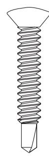
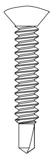
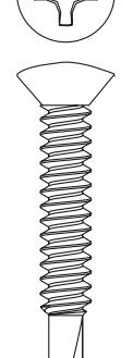
14 x 1-1/2 Oval Head Self Drilling Screw |
Wood | 3/16" (4.76mm) | ||
|
Backplate:
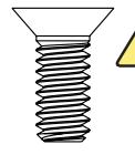
1/4-20 x 1 Flat Head Machine Screw |
Drill #7 (.201 dia. or 5.10mm) | |||
|
Backplate:
1/4-20 x 5/8 Flat Head Machine Screw |
Metal | Tap 1/4-20 | ||
|
Track:
Sex Nut and Bolt (SNB) (optional) |
9/32" (7.00mm) thru
3/8" (9.50mm) door face opposite to closer |
|||
| 3/8" (9.50mm) thru | ||||
Technical Data
| Input power: | 120VAC, 60Hz | NOTES: |
|---|---|---|
|
Power
consumption: |
.9 amps | |
| Circuit breaker: | 3 amps | |
| Power supply: | 24 V DC, max. 2.2 amp. | |
| Door width: | 36" - 48" (91-122 cm) | |
| Door weight: | 100-250 lb. (43-113 kg) | |
| Door opening angle: | up to 110° with reveal of 3" (7.6 cm) max | |
| Hold open time: |
0-30 seconds (A.D.A. 5 seconds min.)
Indefinite for optional Infinite Hold Open |
- y Permanent wiring is to be implemented as required by local codes.
- y Activation devices: push plates, access control, mats, touchless wall switches, etc.
-
y Maximum wire size is:
- ‒ 12AWG at terminals LINE and NEUTRAL (120VAC; 60Hz) on Power Input Terminal mounted on inside of end cap.
- ‒ 14AWG at all other terminals
- y Rate of operation shall not exceed 300 cycles of opening and closing per hour.

Prepare Frame and Doors
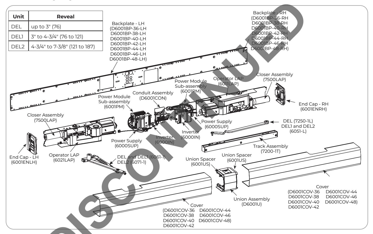
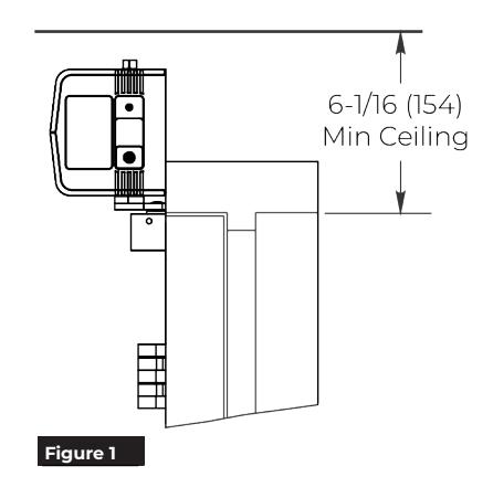
Become familiar with operator components and fasteners. It is recommended that components remain in boxes until installed. Verify there is minimum ceiling clearance for operator installation before proceeding. (Figure 1)
A. Prepare frame.
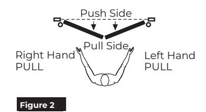
1. Verify correct installation. (Figure 2)
OR
NOTE: These instructions are for Pair of Doors, where door on right is a Push door and door on left is a Pull door. Arms included with this assembly will fail if both doors are Pull doors or if both doors are Push doors. Please contact Customer Service or your local distributor if this is the case.
2. Frame header MUST be flat / without twists. Backplates can be used as reference.
NOTE: If frame is not flat or is twisted, additional steel back plates or shimming is required. Failure to mount units properly can result in improper function of operator or inability to snap on covers.


NOTE: Template provided on page 29.
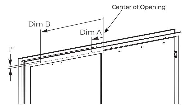
- 5. Measure 1" up from frame rabbet and mark at Dim A and Dim B locations.
- 6. Drill holes.
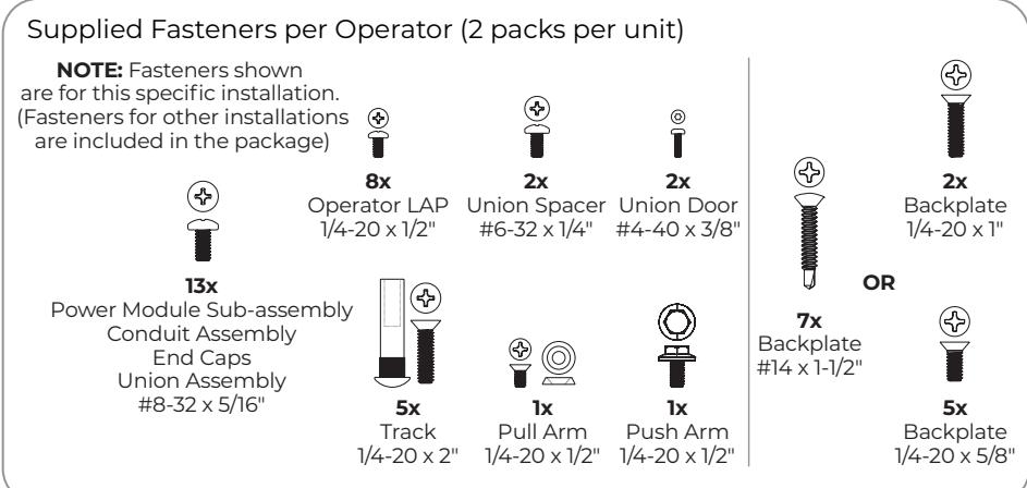
- 7. Using supplied backplate screw pack in Box 1, insert screws into prepared mounting holes.
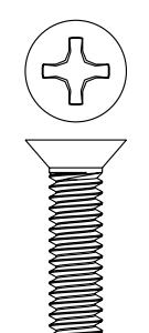
For Metal Frame: Use two (2) 1/4-20 x 1" flat head machine screws.
For Wood Frame: Use two (2) #14 x 1-1/2" oval head self-drilling screws.
NOTE: Do not tighten mounting screws at this time. Leave 5/16" minimum (thickness of backplate) between frame face and back of screw head.
|
Door Size
Dim A |
Dim B | |
|---|---|---|
| Pair of 36" doors: | 5-9/16" (141mm) | 30-9/16" (776mm) |
| Pair of 38" doors: | 7-9/16" (192mm) | 32-9/16" (827mm) |
| Pair of 40" doors: | 9-9/16" (243mm) | 34-9/16" (878mm) |
| Pair of 42" doors: | 11-9/16" (294mm) | 36-9/16" (929mm) |
| Pair of 44" doors: | 13-9/16" (344mm) | 38-9/16" (979mm) |
| Pair of 46" doors: | 15-9/16" (395mm) | 40-9/16" (1030mm) |
| Pair of 48" doors: | 17-9/16" (446mm) | 42-9/16" (1081mm) |
Figure 3
5

B. Mount Backplates.
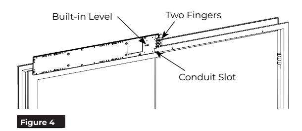
1. Select backplate with 2 small "fingers" for interlocking plates and marked "Mount This Plate First" from Box 1. (This is LEFT backplate.)

OR

NOTE: Left backplate conduit slot is ALWAYS at bottom of plate and toward center of opening.

4. Interlock right backplate (3 small "fingers") from Box 2 with left backplate. (Figure 5)
NOTE: Right backplate conduit slot is ALWAYS at bottom of plate and center of opening.

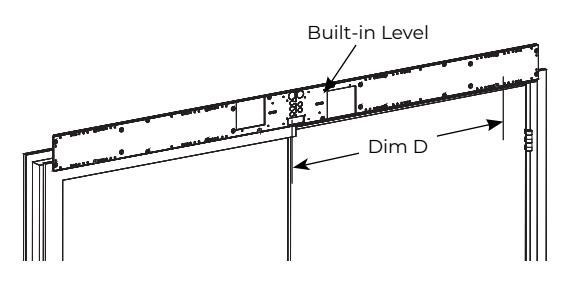
6. Using backplate as template, mark conduit slot and Dim D mounting hole. (Figure 5)
NOTE: Dim D should be 1" up from frame rabbet if backplate is properly aligned.
7. Drill hole for mounting screw at Dim D.
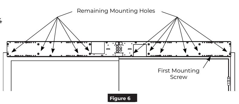
8. Using supplied backplate screw pack in Box 2, insert screw into prepared mounting hole. (Figure 6)
For Metal Frame: Use one (1) 1/4-20 x 1" flat head machine screw.
For Wood Frame: Use one (1) #14 x 1-1/2" oval head self-drilling screw.
NOTE: Do not tighten mounting screw at this time. Leave 5/16" minimum (thickness of backplate) between frame face and back of screw head.
9. Using countersunk holes in backplates as a template, drill/tap remaining eleven (11) mounting holes: 1/4-20 for steel frame or #14 for wood frame. (Figure 6)
| Door Size | Dim D |
|---|---|
| Pair of 36" doors: | 30-9/16" (776mm) |
| Pair of 38" doors: | 32-9/16" (827mm) |
| Pair of 40" doors: | 34-9/16" (878mm) |
| Pair of 42" doors: | 36-9/16" (929mm) |
| Pair of 44" doors: | 38-9/16" (979mm) |
| Pair of 46" doors: | 40-9/16" (1030mm) |
| Pair of 48" doors: | 42-9/16" (1081mm) |
Figure 5

C. Secure Backplates.

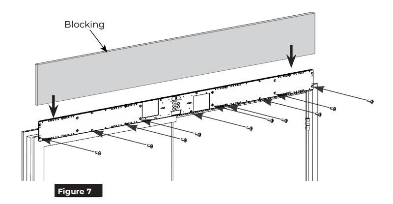
1. Secure backplates to frame using eleven (11): 1/4-20 x 5/8" machine screws or 1/4 x 1-1/2" self-drilling screws from screw packs in Boxes 1 and 2 (Figure 7).
OR
NOTE: It is important to properly secure top edge of backplate. Use of blocking (supplied by others) or shims (provided) to fill gap between backplate and wall above header is HIGHLY recommended. Material must comply with local codes. Failure to properly secure top of backplate could result in operator being allowed to 'rock' during operation. This could result in damage to operator and diminish operator function. (Figure 7)
D. Prepare doors for Track and Arm Shoe.
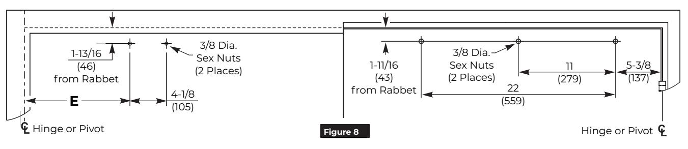
1. Locate and prepare track holes in door. (Figure 8)
NOTE: Template provided on page 29.
2. Drill 3/8" (9.5mm) through (3 places) for sex bolts.
3. Locate and prepare arm shoe holes in door. (Figure 8)
NOTE: Template provided on page 29.
4. Drill 3/8" (9.5mm) through (2 places) for sex bolts.
|
Door
Opening Angle |
85° | 90° | 95° | 100° | 105° | 110° |
|---|---|---|---|---|---|---|
| Dimension G | 13-1/4" | 12-5/8" | 12" | 11-1/2" | 11-1/8" | 10-3/4" |
| (337mm) | (320mm) | (305mm) | (292mm) | (283mm) | (273mm) |
| Model | Dim H |
|---|---|
| DEL | 5-3/8" (137mm) |
|
DEL1
DEL2 |
7-3/4" (197mm) |

Install Operators
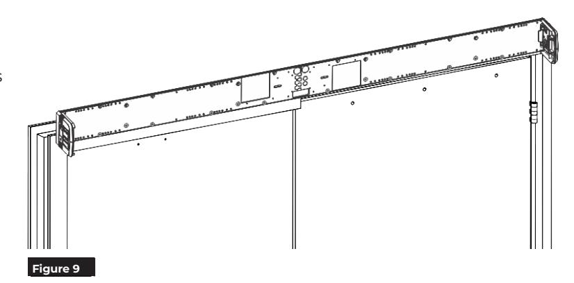
A. Install End Caps.
1. Secure end caps to each end of connected backplates using four (4) (two each) #8-32 x 5/16" Phillips pan head screws. (Figure 9)
NOTE: Orient end caps so that text on labels is legible when observed from ground.
B. Install Operator LAPs.
NOTE: Backplates are printed with text to assist installation.
1. With backplates mounted to frame, use text to locate holes along bottom of backplates that correspond to your specific closer installation -6061/6071 plus open angle for left door and 6011/6051 for right door . (Figure 10)
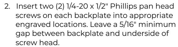
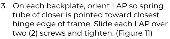
NOTES:
- y LAP for left door should have "PUSH" label and door closer valves should point toward chain. LAP for right door should have "PULL" label and door closer valves should point away from chain.
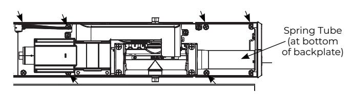
- y When properly oriented, spring tube is at top on left hand backplate (Figure 11) and at bottom on right hand backplate.
- 4. For each LAP, use six (6) 1/4-20 x 1/2" Phillips head screws to secure. (Figure 12)
NOTES:
- y Holes in LAP align with threaded holes in backplate.
- y Screws to be torqued to 80 in-lb minimum.
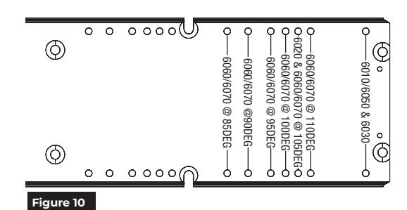
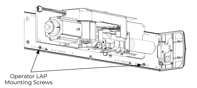
Figure 11 Right Door LAP shown
Remaining LAP Mounting Screws - Right Door View Figure 12
80-9360-1037-020 Rev 4 01/23

C. Install Conduit Assembly and wire to building.
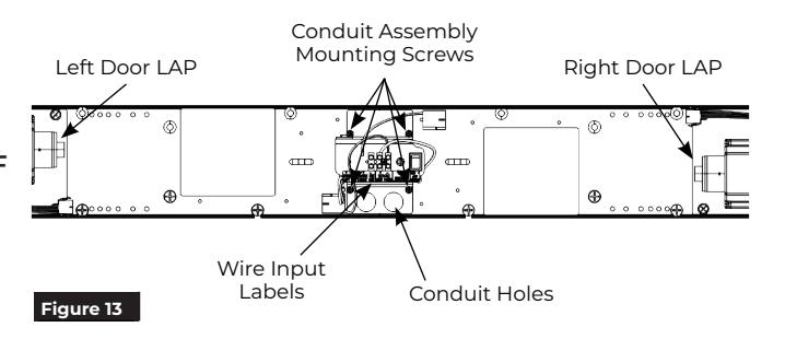
- 1. Orient conduit assembly so two (2) conduit holes are at bottom and text on wire input label is legible. (Figure 13)
- 2. Secure assembly to backplate using four (4) #8- 32 x 5/16" Phillips head screws. (Figure 13)

WARNING: BUILDING POWER MUST BE OFF BEFORE PROCEEDING!
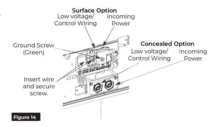
- 3. Secure conduits to conduit assembly (surface or concealed conduit). (Figure 14)
- 4. Wire building 120VAC to conduit assembly LINE, NEUTRAL, and GROUND. (See General Electrical Information on page 16.)
- 5. Wire 24VDC for accessories to conduit assembly 24VDC + / - as required. (See General Electrical Information on page 16.)

WARNING: DO NOT TURN ON BUILDING POWER UNTIL DIRECTED TO DO SO! RISK OF INJURY OR DEATH!
D. Install Power Module Sub-assemblies.
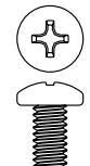
1. Using three (3) #8-32 x 5/16" Phillips screws per assembly, secure power module sub-assemblies to backplate at location marked on backplates. (Figure 15)
NOTE: Orient assemblies so LCD screens on inverters are toward corresponding closer assemblies. (Figure 15)
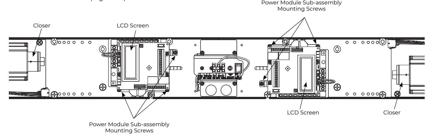
Figure 15 Wiring Removed From View

E. Connect Power Module Sub-assemblies to LAPS.

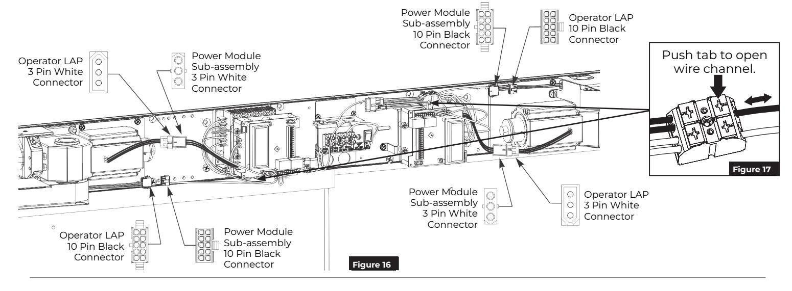
Power module wiring may loosen during shipping. Gently tug each wire on the connector. If a wire is loose, push the connector tab and reinsert wire. Release tab and verify the wiring is secure. (Figure 17)
- 1. Attach 10-pin black connectors between each power module sub-assembly and its operator LAP. (Figure 16) NOTE: Connectors are keyed and only attach one way.
- 2. Attach 3-pin white connectors between each power module sub-assembly and its operator LAP. (Figure 16)
F. Install Union Assembly.
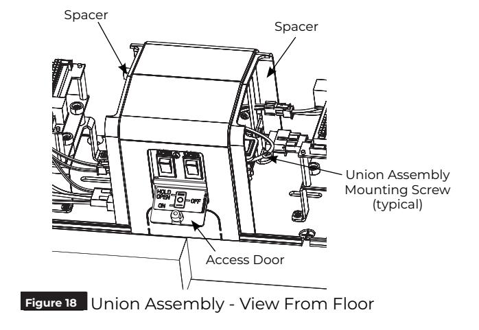
1. Orient union assembly so access door covering selector mode switches faces floor. (Figure 18)
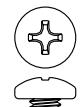
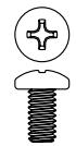
2. Secure union assembly to backplate using four (4) #8-32 x 5/16" Phillips pan head screws. (Figure 18)
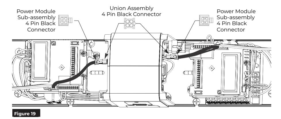
NOTE: Connectors are keyed and only assembly one way.

Install Arms to Left Door
A. Mount Forearm and Shoe.
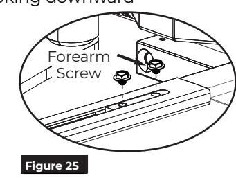
1. Using previously prepared holes in door, install two (2) 1/4-20 x 1-5/8" screws through shoe and into sex bolts. (Figure 20)
NOTE: Orient shoe with long side of shoe toward hinge. (Figure 21)
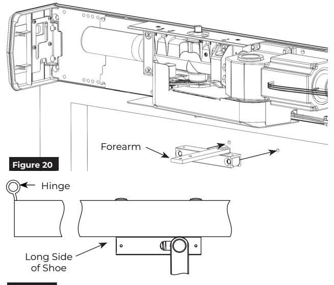
Figure 21 View from ceiling looking downward
B. Install Main Arm.
- 1. Open left door.
- 2. Slide forearm into main arm adjusting tube. (Figure 22)
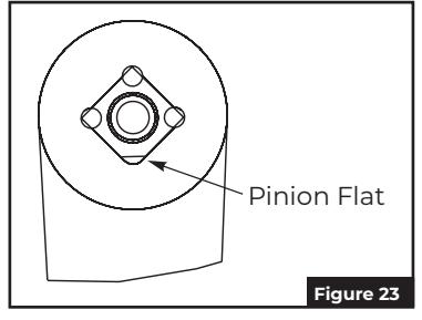
- 3. Place square of main arm onto closer pinion. (Figure 22)

NOTE: Pinion flat should be aligned as shown. (Figure 23)

5. With door closed, rotate main arm away from hinge until forearm is perpendicular (90 degrees) with door. (Figure 24)

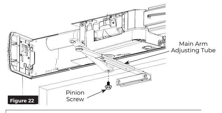
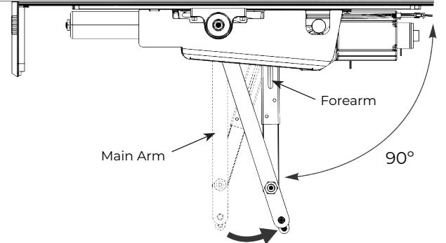
Figure 24 View from ceiling looking downward

Install Track and Arm to Right Door
A. Mount Track.
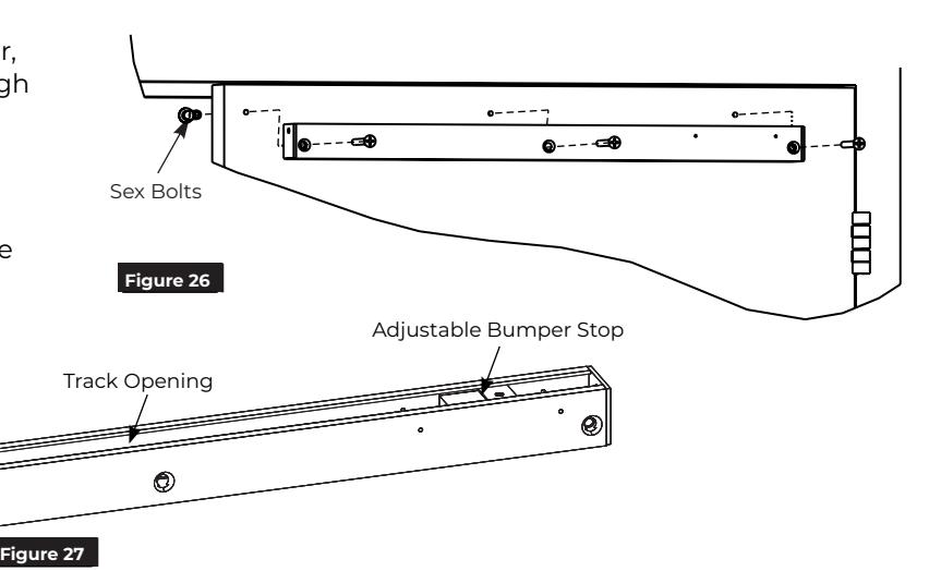
1. Using previously prepared holes in left door, install three (3) 1/4-20 x 1-5/8" screws through track and into sex bolts. (Figure 26)
NOTES: (Figure 27)
- y Opening of track is toward top of door.
- y Adjustable bumper stop is toward hinge edge of door.

- 1. Open right door.
- 2. Using an adjustable wrench, rotate top pinion 45 degrees toward door hinge. You will feel resistance from spring. (Figure 28)
- 3. While holding pinion at 45 degrees , slide arm on bottom pinion parallel to frame as shown. (Figure 28)

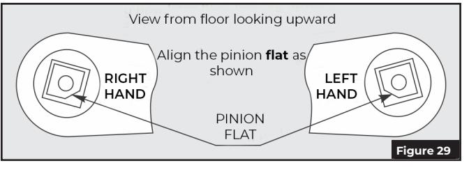
NOTE: Pinion flat should be aligned as shown. (Figure 29)

- 4. Secure arm to pinion with 1/4-20 x 1/2" screw and countersunk patch washer. (Figure 28)
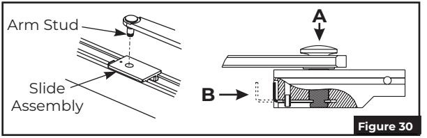
- 5. Insert stud on arm into slider in track by pressing clip on backside of slider onto stud. (Figure 30)


- y Open door to full open position.
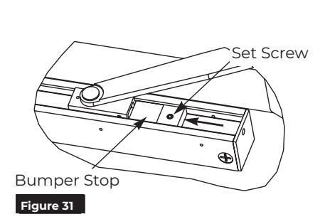
- y Slide bumper stop until it just touches end of slider.
- y Tighten set screw in bumper stop so bumper will stay in position. (Figure 31)


Sweep
Slowe
Chain Protection Plate
Adjustments
A. Adjust mechanical closer features on each operator.
- Make necessary mechanical adjustments so unit functions as a standard surface mounted door closer before adjusting spring force, applying power, adding accessories or making electrical/programming adjustments.
- Valve location S/D is not adjustable.
- Chain protection plate cutouts allow access to valves. Use hex wrench to make adjustments. (Figure 32)

Do not remove valves from closer. Hydraulic oil will escape.
-
1. Closing Speed Controls (Figure 32)
- Valve "S" controls Sweep Range from full open to 10°.
- Valve "L" controls Latch Range from 10° to closed.
-
2. Opening Cycle (Figure 32)
- Valve "B" controls strength of cushioning in Backcheck Range.

NOTE: NEVER close Backcheck valve completely – it is not to provide a positive stop.
Valve "P" adjusts angle that backcheck is felt in open cycle. Factory preset is typically acceptable.
Back check Back check Position Stronger Veaker
Latch
Slower
Figure 32 View of Right Door operator from ceiling looking down
B. Adjust spring force on each operator.
- The amount of effort to manually open or close a door is called force and is controlled by the operator's closer spring.
- Make necessary mechanical adjustments described in "A" above.
- A closer set to ADA required 5 lbs opening force may not be strong enough to close door due to latching hardware, air pressure, or frame issues.
Push Side Unit: Using an adjustable wrench or a ratchet with an 11/16" socket, turn the nut in end of closer body tube clockwise to increase or counterclockwise to decrease force until desired setting is reached. (Figure 33)
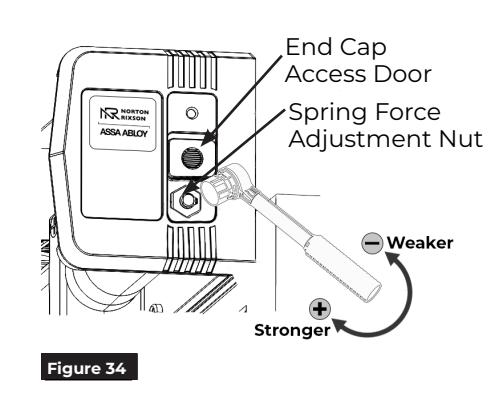
Pull Side Unit: To adjust the spring force, access the Spring Force Adjustment Nut through the End Cap Access Door.
- 1. Remove the small torx head screw from end cap.
- 2. Slide the End Cap Access door, exposing the spring adjustment nut.
- 3. Using a ratchet with an 11/16" socket, turn the nut in end of closer body tube clockwise to increase or counterclockwise to decrease force until the desired setting is reached. (Figure 34)
-
4. Once the desired force has been set:
- Remove the ratchet.
- Slide the end cap access door closed.
- Replace the end cap screw.
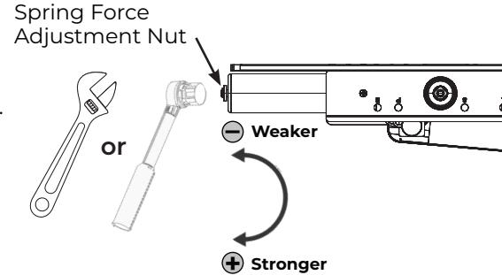
Figure 33 View from ceiling looking downward

Power Operators
- 1. Remove #4-40 Phillips screw to open door on union assembly and place each selector mode switch in 'OFF' position. (Figure 35)
- 2. Turn On/Off switch to 'OFF' position on conduit assembly. (Figure 35)
- 3. Turn on building power.
- 4. Turn On/Off switch to 'ON' position on conduit assembly.

WARNING: Door may begin to move immediately when power is applied to unit. An open union assembly door has potential to pinch fingers if hand is not withdrawn quickly when switching on power.
See Controller Interface Description on page 18 for controller adjustment options.
- y To scroll through menu items, push up or down on joystick. (Figure 35)
- y To change setting of a menu item, when cursor is on that item, push joystick left/right to increase/decrease value.
-
5. Set 'HOME' procedure for both doors.
- y With door closed and union assembly selector mode switch in "OFF" position, use joystick to scroll down menu on LCD screen to "Home".
- y Push in on joystick to activate menu feature. Display changes to "Set Close Limit".
- y Push in on joystick again, while door is still closed, to set Home or closed position (Figure 36). Display changes to "Set Open Limit".
- y Open door to desired open position (Figure 36) and push in on joystick again. Display changes to "Closing to Home".
- y Allow door to fully close again (Figure 36). Display changes to "Home".
NOTE: Values will auto-save.
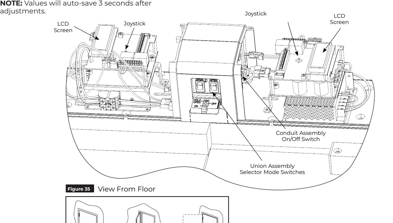
Figure 36

Sync Operators
- 1. Determine which door will be Master.
-
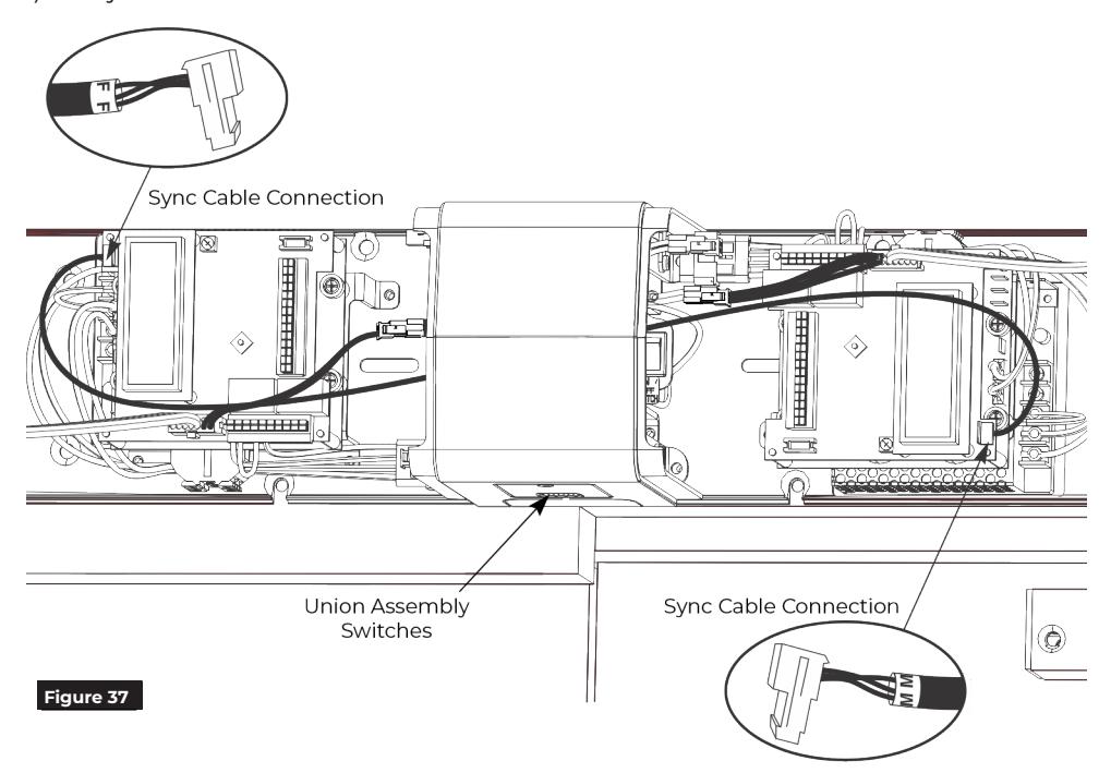
2. Run Sync Cable between operators. (Figure 37)
- y Attach end of Sync Cable marked "M" to 4-pin connector on top of inverter board on unit selected as Master Door.
- y Attach other end of Sync Cable marked "F" to 4-pin connector on top of inverter board selected as Follower Door.
NOTE: Connectors are keyed and only attach one way.
3. To set up inverter for Master - Follower functionality:
Master Unit:
- • go to Page 2 on inverter screen
- • scroll down to Single
- • increase to Dbl:Master or *Dbl:MasterCoord
Follower Unit:
- • go to Page 2 on inverter screen
- • scroll down to Single
- • increase to Dbl:Follower
*NOTES:
‒ Dbl:MasterCoord to be used when astragal or similar is attached to Master door or as a replacement for a mechanical door coordinator. Once set, Master door will open slightly before Follower door during opening cycle. Upon closing, if Master door reaches a set door opening position (MasterStopOffset) and Follower door has not reached full closed position, Master door will stop and wait for Follower door to reach fully closed and then close. The point at which Master door stops (Master-StopOffset) is adjustable.
- ‒ If Dbl:MasterCoord is used and Follower door is opened manually, Master door will automatically open to MasterStopOffset position until Follower door has reached fully closed position and then close.
- 4. Make necessary adjustments to Master Door inverter only, add activation to Master Door inverter only, and add required accessories to each door.
NOTE: Settings will automatically transfer over to Follower Door inverter.
5. Place both selector mode switches of union assembly in 'ON' position for activation by push plate, RF button, or other activation devices. Place switches in 'H/O' for continuous hold open. (Figure 37)

WARNING: Door may begin to move immediately when selector mode switch is changed. An open union assembly door has potential to pinch fingers if hand is not withdrawn quickly when adjusting selector mode switch.
6. Secure union assembly door with #4-40 Phillips screw removed in Step 1 on page 14.
NOTE: For security applications, torx head screws are provided in screw pack for use on union doors.
You've now installed the D6001DE-L Low Energy Operator. Continue with Electrical Instructions to customize the installation.

Finalize Installation
Attach Covers to finalize installation
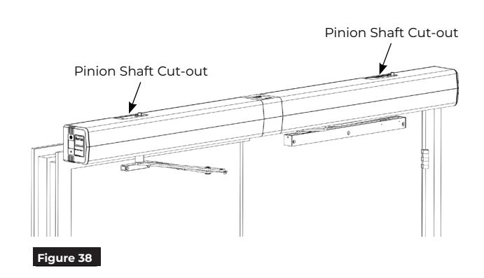
- 1. Align cut-outs in each cover to corresponding pinion shafts. (Figure 38)
-
2. Slide covers onto units using end caps and union spacers as guides.
- NOTE: Verify all wiring and sheet metal guards are inside cover.
- 3. Snap covers securely to backplates. Pull on covers to verify they are secure.
NOTE: If cover will not securely snap onto backplate, verify backplate is not warped or twisted. Additional support or shimming may be required. See Sections A & B under Prepare Frame and Door.

WARNING: Make sure no wiring is loose or can be caught by cover when it is snapped into place.
General Electrical Information
- y Power inputs at power input connection and power output contacts must be made with copper wire only.
- y Maximum wire size: 12 AWG at power input connection 14 AWG at all other terminals.
- y Power input at terminals LINE and NEUTRAL must be 120VAC at 60 Hz (+10%, -15%).
- y Maximum current draw from auxiliary devices is 1.3 amps.
- y All wiring and connections use standard wiring practice conforming with local wiring codes.
- y Labeled fire or smoke barrier door assemblies require 120VAC 60Hz power input be supplied through normally closed alarm contacts of the alarm system / alarm panel.
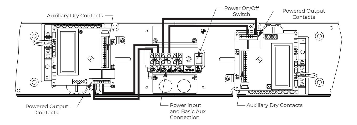

Wiring Options
Factory Pre-Wiring of Connections and Incoming Wiring
To connect wiring:
For Incoming 120VAC and 24VDC for accessories
- 1. For 20 10 AWG wire
- 2. Strip end of wire 1/4 inch
- 3. Insert wire into appropriate position as shown and use flat head screw driver to secure.
For Low Voltage / Dry Contacts on Inverter
- 1. For 24 16AWG wire
- 2. Strip end of wire 3/8 inch
- 3. Use flat head screw driver to push down on white button above desired location, insert wire, release button. Pull on wire to confirm installed properly.
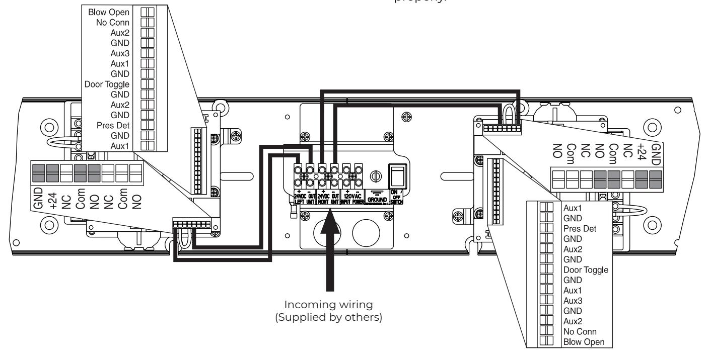
Controller Error Codes
| Error Code | Description |
|---|---|
| Short Circuit | A short was sensed on the motor outputs |
| Temperature Trip | Power module reached 200°F or greater (too much load in too hot ambient condition) |
| Over Voltage | Line Voltage has reached 145VAC or greater |
| Under Voltage | Line Voltage has dropped below 80VAC |
| Aux 1 Stuck | Activation device connected to Aux 1 is sending constant signal |
| Aux 2 Stuck | Activation device connected to Aux 2 is sending constant signal |
| Aux 3 Stuck | Activation device connected to Aux 3 is sending constant signal |
| Comm Error |
No communication between top and bottom controller boards. Boards not
functioning properly |
| Presence Detect | Device connected to Presence Detect and was activated |
| Drive Disabled | Selector mode switch on end cap closest to latch is in "OFF" position |
17

Controller Interface Description
| Screen 1 | Adjustments | Default | Description |
|---|---|---|---|
| Mount: | Push or Pull | Push | Side of opening operator is mounted on |
| Hold Open: |
0 - 30 sec in 1 sec
increments |
4s | Amount of time door will stay in full open position after an activation |
|
Open Delay
(previously Start Delay): |
0 - 10 sec in 1 sec
increments |
0s | Time before operator begins to open door. Allows accessories time to function and not hinder opening of door |
| Latch Rtrct: | OFF, 3 - 45 sec in 5 sec increments | OFF | Amount of time power is supplied to a latch retraction device |
| Home: |
see Setting Open
Position |
_ | Used to set Home position and Fully Open position of door |
| Vestibule: | OFF, 5 - 30 sec in 5 sec increments | OFF | Amount of delay for opening 2nd vestibule door |
| Push: | OFF or Push & Go | OFF | Turn on or off Push & Go feature. If On, a slight push or pull of the door starts automatic opening. |
| Open Speed: | 0 - 100% in 1% increments | 120 | How fast door opens to full open position |
| Close Speed: | 0 - 100% in 1% increments | 80 | How fast motor returns to home position. As Latch and Sweep on closer are adjusted, adjustments may be needed for Close Speed to assure closer is not trying to backdrive motor. |
| Errors: | not adjustable | _ | Error code seen by controller. See Controller Error Codes on page 17. |
| Screen 2 | Adjustments | Default | Description |
| Door Feedback: | not adjustable | _ |
General feedback. Includes Door State, Door Position, Motor Position, Open
Limit, Close Limit |
| Drive Feedback: | not adjustable | _ | General feedback. Includes Bus Voltage, Bus Current, Frequency |
| Usage: | not adjustable | _ |
General feedback. Includes Open Time, Close Time, Days, Cycles, Firmware
Rev |
| Single: |
Single Door, Dble:Follow,
Dble:Master, Dble:Mast Coord |
Single | Set on Single for a single, stand alone door. Dble:Follow for Follower door on pair of doors. Dble:Master for Master door on a pair of doors. Dble:Mast Coor for Master door on a pair of doors when door coordination is needed. |
| MastStopOffset: | 0-500 | 180 | Adjustable point where Master Coord door will stop and wait for Follower door to fully close so Follower does not contact astragal attached to Master Coord door |
| Follow Delay: | 0-5 sec in 1 sec increment | 0s | Amount of delay for Follower door after Master door has started to open |
| PDET Option: | On, Off | Off | On or Off for 585 Presence Detector |
| DT: |
Standard,
SS1:Stall, SS1:Return Open, SS1:Stall /Open |
Stnd | Standard is Door Toggle. SSI:Stall - when sensor detects an obstruction in opening as door is closing, door will stall until obstruction is removed. SSI:Return Open - when sensor detects an obstruction in opening as door is closing, door will stop and return to full open position until obstruction is removed. SSI:Stall/Open - when sensor detects an obstruction in opening as door is closing, door will stall until obstruction is removed and door will return to full open position. |
| A2: |
Standard,
SS2:Stall, SS2:Return Home, SS2:Stall /Home |
Stnd | Standard is Activation mode - just like AI activation. SS2:Stall - when sensor detects an obstruction in opening as door is opening, door will stop until obstruction is removed. SS2:Return Home - when sensor detects an obstruction in opening as door is opening, door will stop and return to full closed position until obstruction is removed. SS2:Stall/Home - when sensor detects an obstruction in opening as door is opening, door will stop until obstruction is removed and door will return to full closed position. |
| Rly2: |
Alarm, Activation, On
Opened, On Closed |
Alarm | How Relay 2 is used: Alarm - used with above Alarm Delay; Activation - acts as an additional NO/NC contact; On Opened - relay trips (closed contacts) when door is in opened position; On Closed - relay trips (closed contacts) when door reaches fully closed position. |
| Alarm Delay: | OFF, 30 sec, 60 sec | OFF | Used only for alarm accessories |
| Slow Speed: | 0 - 100% in 1% increments | 55 | Speed up or slow down door during last few degrees of opening |
| Hold Speed: | 0 - 100% in 1% increments | 55 | Increase or decrease hold open force (when in "ON" position only, not "H/O") to compensate for spring force, wind conditions, etc. |
| Obst Delay: |
0 - 5 sec in 1 sec
increments |
3s | Obstruction Delay: amount of time operator will push against an obstruction before closing if during an opening cycle or reopening and trying to close again if during a clocking cycle. |
80-9360-1037-020 Rev 4 01/23

Basic Double Door Wiring Diagrams Using Factory Pre-Wired Connection Standard Function with Switches
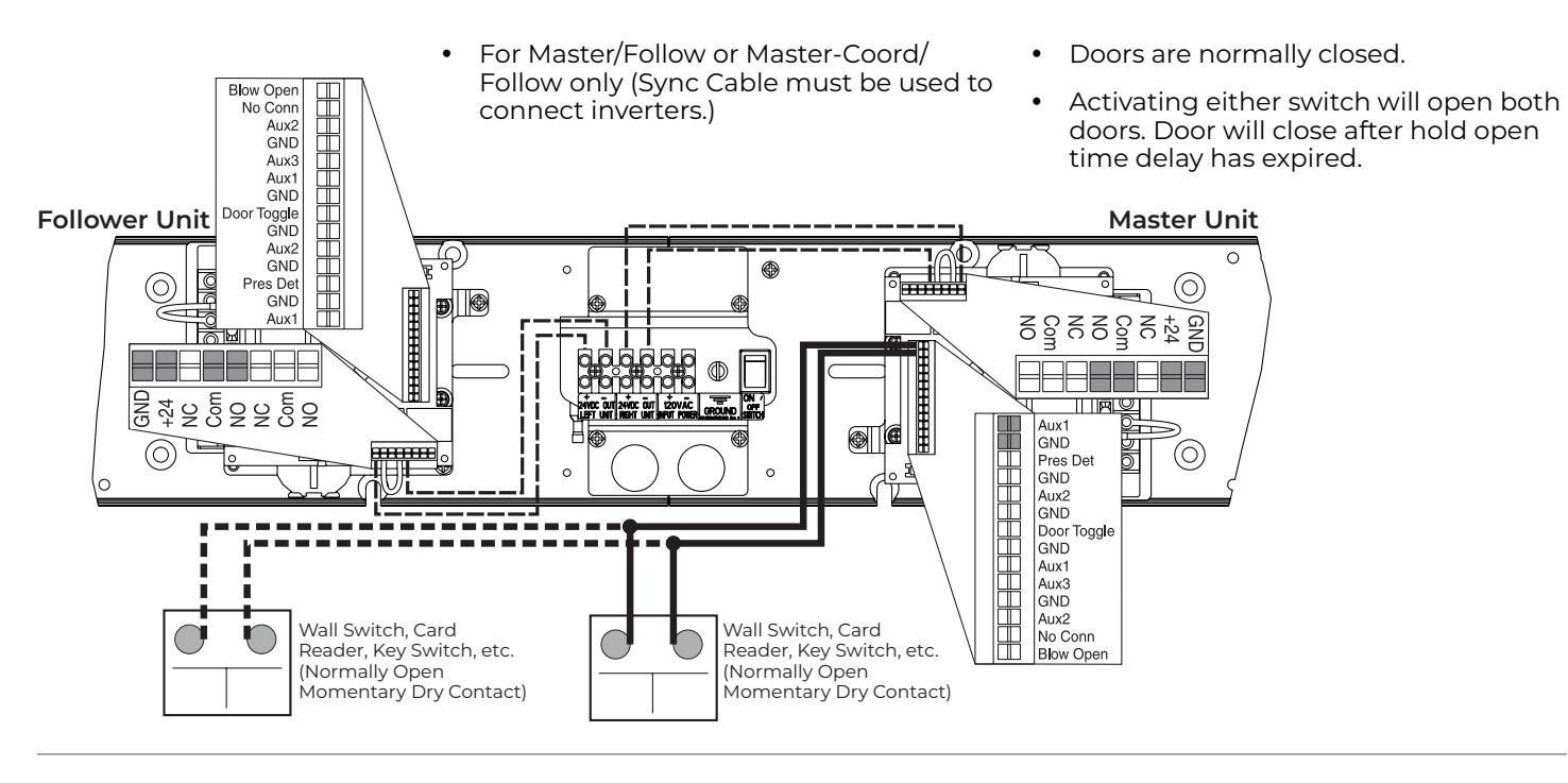
Fail Secure Electric Strike 24VDC Wiring
- y For Master/Follow or Master-Coord/ Follow only (Sync Cable must be used to connect inverters.)
- y Activating switch will unlock electric strike and door will automatically open. Door will close after hold open time delay has expired.
- y Door will remain locked during power
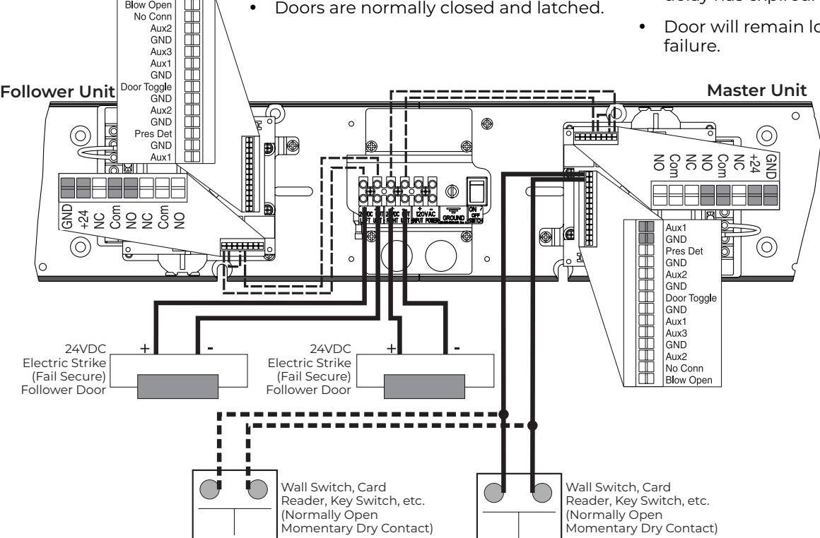

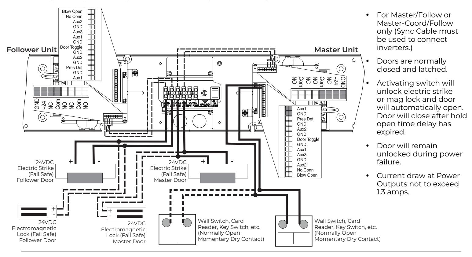
Double Door Fail Safe Electric Strike or Electromagnetic Lock 24VDC Wiring
Change Factory Pre-Wiring to Illustration Below (move NO to NC)
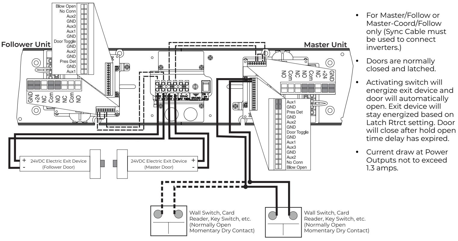
Double Door 24VDC Electric Exit Device Wiring
Factory Pre-Wiring in Illustration is for this functionality

Double Door Electric Dogging Exit Device Wiring
Change Factory Pre-Wiring to Illustration Below (move NO to +24)
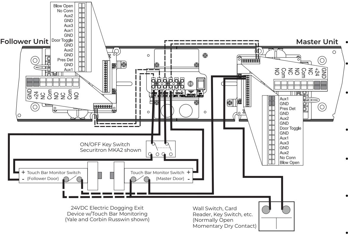
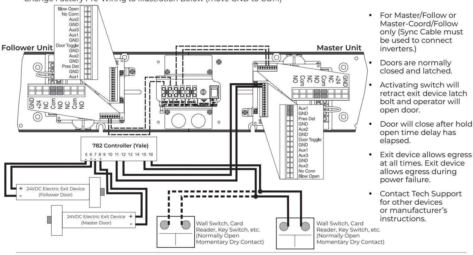
- y For Master/Follow or Master-Coord/Follow only (Sync Cable must be used to connect inverters.)
- y Doors are normally closed and latched.
- y Turning key switch ON will apply power to exit device.
- y First depression on device touchpad will electrically dog device for push/pull operation.
- y Door will now open automatically when wall switch is depressed.
- y Device will re-latch during a power failure or when key switch is turned off.
- y Exit device allows egress at all times. Exit device allows egress during power failures.
- y Current draw at Power Outputs not to exceed 1.3 amps.
Double Door Hard Wired Executive Function Wiring
Factory Pre-Wiring Not Required to Change
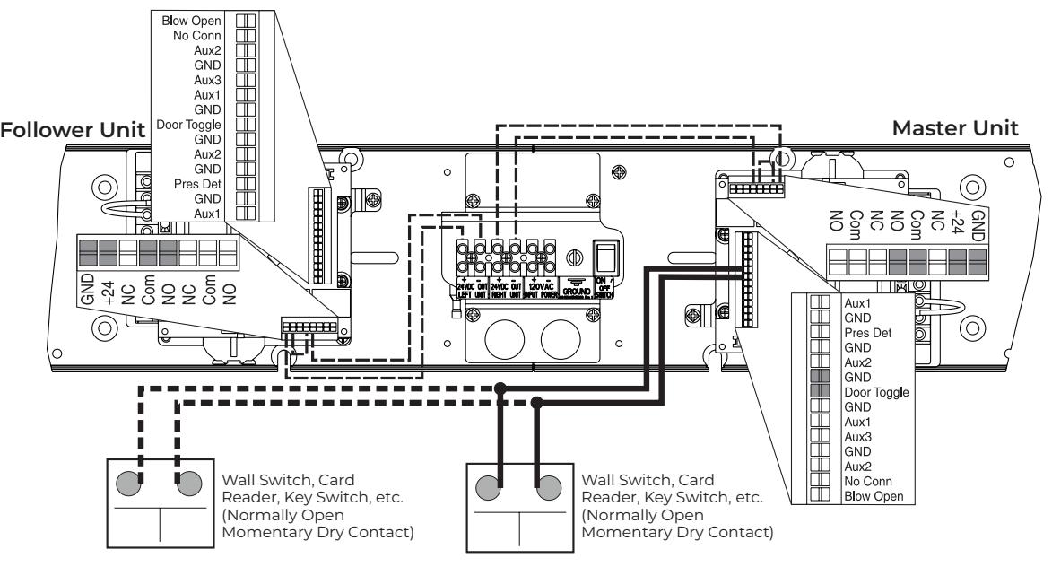
- y For Master/Follow or Master-Coord/Follow only (Sync Cable must be used to connect inverters.)
- y Doors are normally closed.
- y Activating switch will open door.
- y Door will remain in indefinite hold open until activating switch is activated a second time causing door to close.

Double Door Electric Latch Retraction Exit Device Wiring
Change Factory Pre-Wiring to Illustration Below (move GND to COM)
Double Door Electric Latch Retraction Exit Device Wiring for Smoke Ventilation - Blow Open Function
Change Factory Pre-Wiring to Illustration Below (move GND to COM)
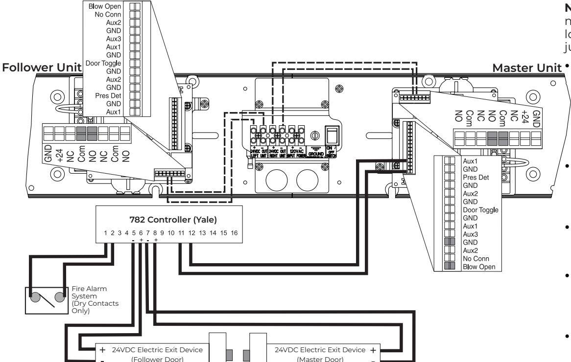
NOTE: This application must be approved by local authority having jurisdiction (AHJ).
- For Master/Follow or Master-Coord/Follow only (Sync Cable must be used to connect inverters.)Doors are normally closed and latched.
- Fire Alarm activation will retract exit device latch bolt and door operator will open door.
- Door will remain open until the Fire Alarm System has been reset.
- Door Operator's main power input must be wired into building's back-up power system.
- Exit device allows egress at all times. Exit device allows egress during power failure.
Experience a safer and more open world

Double Door Radio Frequency Standard Function Wiring
If Installing in the Field, change Factory Pre-Wiring to Illustration Below (move NO to +24)
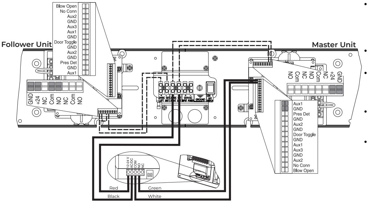
- y For Master/Follow or Master-Coord/Follow only (Sync Cable must be used to connect inverters.)
- y Doors are normally closed.
- y Activating wireless switch or hand held wireless transmitter will open door.
- y Door will close after hold open time delay has elapsed.
- y Current draw at Power Outputs not to exceed 1.3 amps.
Double Door Radio Frequency Executive Function Wiring
If Installing in the Field, change Factory Pre-Wiring to Illustration Below (move NO to +24)
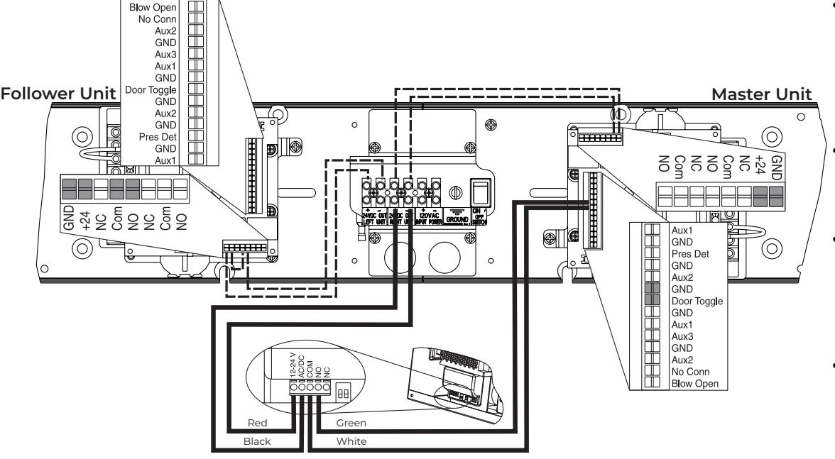
- y For Master/Follow or Master-Coord/Follow only (Sync Cable must be used to connect inverters.)Doors are normally closed and latched.
- y Activating wireless switch or hand held wireless transmitter will open door.
- y Door will remain in indefinite hold open until wireless switch or hand held transmitter is activated a second time causing door to close.
- y Current draw at Power Outputs not to exceed 1.3 amps.

Double Door Vestibule Function Wiring Using Factory Pre-Wiring
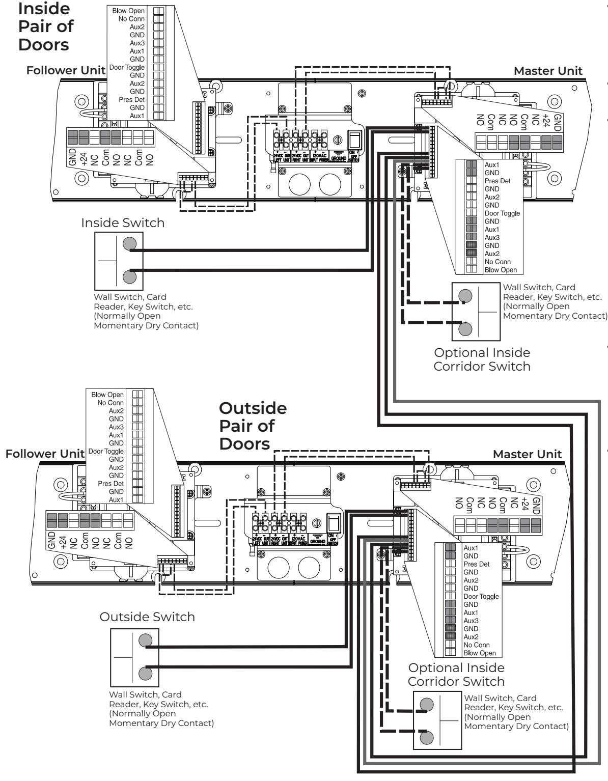
Approved 2023-01-24
- y For Master/Follow or Master-Coord/Follow only (Sync Cable must be used to connect inverters.)
- y Doors are normally closed and latched.
- y Activating outside door switch will open outside door. After vestibule time delay has elapsed, a signal will be sent to inside door which will open. Activating inside door switch will open inside door. After vestibule time delay has elapsed, a signal will be sent to outside door which will open. Both doors will close when hold open time delay has elapsed.
- y Activating optional inside door switch located within corridor will open inside door only. This door will reclose after hold open delay has elapsed.
- y Activating optional outside door switch located within corridor will open outside door only. This door will reclose after hold open delay has elapsed.

433MHz Receiver User's Guide
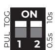
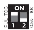
In Toggle Setting (1-ON), Hold Time is inactive. Either setting for #2 dip switch will have same result.
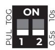
0.5 second Pulse Setting
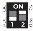
10 second Pulse Setting
| #1 | Description | Function |
|---|---|---|
| OFF | Pulse Relay | Press transmitter once and relay will be active momentarily. |
| ON | Toggle Relay |
Press transmitter once and relay output is active indefinitely.
Press it again and relay will de-energize indefinitely. |
| #2 | Description | Function |
| OFF | 0.5s Hold Time | Relay will remain active 0.5 sec after loss of activation. |
NOTES:
- y Always stop pedestrian traffic through doorway when performing tests that may result in unexpected reactions by door.
- y Ensure compliance with all applicable safety standards upon completion of installation.
- y See diagrams on page 23 for wire colors.
Hand-Held Configuration
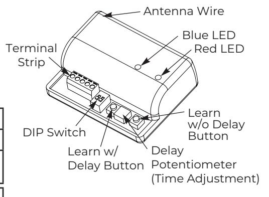
- 1. Set dip switches to receiver to desired activation cycle (dip switch 1 - Toggle or Pulse and dip switch 2 - 0.5s or 10s hold.
- 2. Press either Learn w/ Delay Button or Learn w/o Delay Button on receiver depending on activation requirements (if delay learn is selected, adjust potentiometer to counterclockwise limit, 0 second delay). Red LED on receiver will flash. After learn cycle is complete, adjust potentiometer to desired delay time (0 - 30 sec).
- 3. Depress transmitter button repeatedly until Blue LED on receiver illuminates (indicating reception of signal from transmitter).
NOTE: Repeat Steps 2 - 3 to program additional transmitters.
4. To test system, depress transmitter button (Red LED on Transmitter will illuminate) and observe that Blue LED illuminates on receiver. This indicates that relay has been activated.
Push Plate Configuration
- 1. Before beginning, prepare installation of push plate.
- 2. Connect wires from transmitter to NO and COM contacts of push plate's switch.
- 3. Follow Steps 1 4 (Hand-Held Configuration); depress push plate to activate transmitter.
- 4. Attach transmitter to inside of electrical box and complete installation.
Removing Transmitter Code(s)
Single Transmitter Code:
- y Press both Delay and No Delay Buttons simultaneously until Red LED flashes once (approximately 1 second).
- y Press transmitter button twice within 10 seconds and transmitter code will be deleted.
All Transmitter Codes:
y Press and hold both Delay and No Delay Buttons simultaneously until Blue LED illuminates then release (approximately 10 seconds).
| Troubleshooting | ||||
|---|---|---|---|---|
| Problem | Solution | |||
|
LED on receiver is flickering - unable to
program and/or won't work |
Push plate stuck or faulty transmitter. Disconnect each push plate until LED goes out. If
LED does not go out, remove each transmitter battery until it does. Replace appropriate transmitter. |
|||
|
Receiver intermittently doesn't receive
transmitter(s) signal. |
Extend receiver antenna wire only in multiples of 6-3/4" (171)
Example: 6.75 x 4 = 27" (686) of extended antenna wire. |
|||

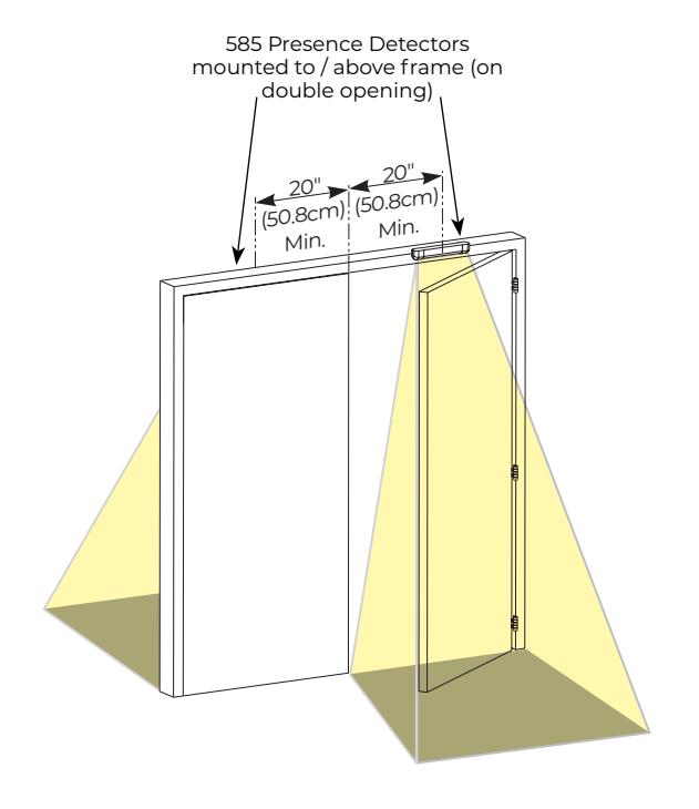
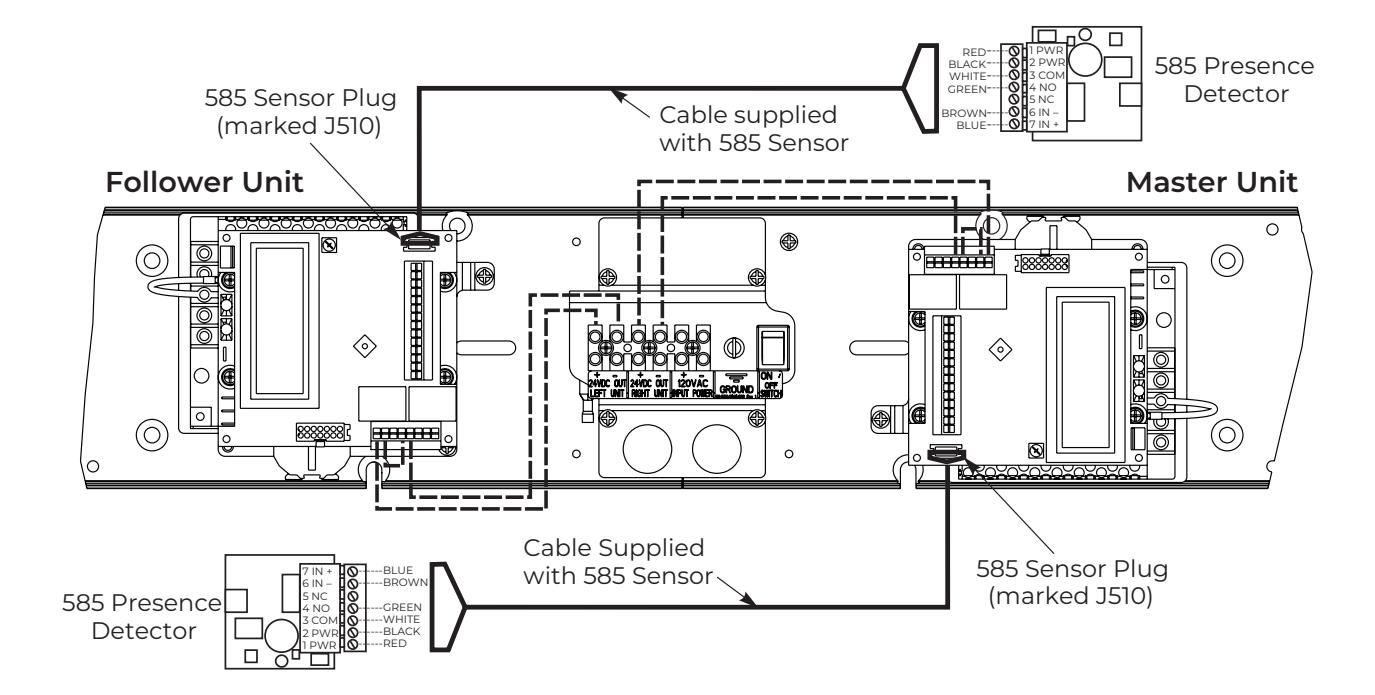
585 Presence Detector Wiring on Double Door Opening
- For Master/Follow or Master-Coord/Follow only (Sync Cable must be used to connect inverters.)
- Door is normally closed.
- · Activating switch will open door.
- Door will close after hold open time delay has elapsed.
- If door is closed and 585 Presence Detector senses something in opening, door will not open.
- If door is at open position and 585 Presence Detector senses something in opening, door will not close.
NOTE: Presence Detector and/or sensors CANNOT be used to active opening cycle of door.
To activate presence detector functionality:
- On inverter, use up/down arrows to scroll to Page 1.
- Use left/right arrows to change to Page 2.
- Use up/down arrows to scroll to PDET Option.
- Use left/right arrows to change value from OFF to ON.
- Use instructions provided with 585 sensor to program and make any necessary adjustments to sensor.

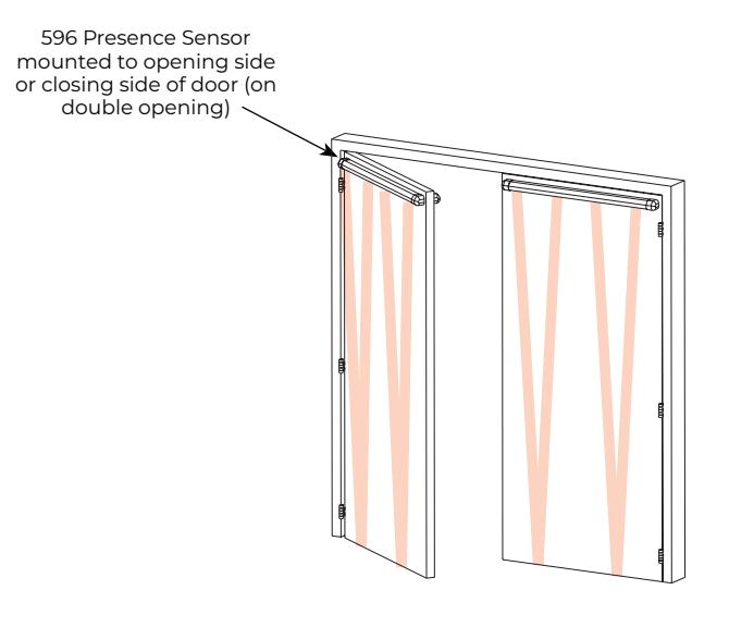
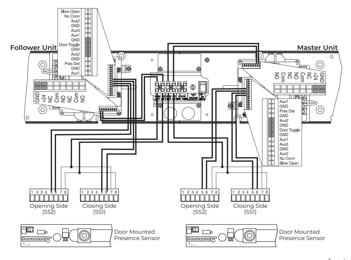
Door Mounted Presence Detector (596 Series) Wiring on Double Door Opening
- y For Master/Follow or Master-Coord/Follow only (Sync Cable must be used to connect inverters.)
- y Doors are normally closed.
- y Activating switch will open door.
- y Door will close after hold open time delay has elapsed.
-
y If using door mounted presence sensors:
- ‒ For Closing cycle sensor (SS1), adjust DT on page 2 of controller screen. If DT is set to Standard, this is normal Door Toggle mode and will not work with Presence Sensor; set to Stall, door closing will stall until presence not sensed; set to Return Open, presence is sensed and door fully reopens; set to Stall/Open, presence is sensed and door will stall then reopen once presence not sensed.
- ‒ For Opening cycle sensor (SS2), adjust A2 Option on page 2 of controller screen. If door is set to Standard, switch or other activation into A2 acts like A1. If A2 set to Stall, door will stop opening and stall until presence not sensed; set to Return Home, door will close back to Home position when presence is sensed; if set to Stall/Home, door will stall and return home once presence not sensed.
NOTE: NOTE: Presence Detector and/or sensors CANNOT be used to active opening cycle of door.

Troubleshooting Guide
| Problem | Solution |
|---|---|
| Door closing too fast |
1) Adjust Latch and/or Sweep valves on closer clockwise OR
2) Decrease Closing Speed on controller (see page 13) |
| Door closing too slow |
1) Adjust Latch and/or Sweep valves on closer counterclockwise OR
2) Increase Closing Speed on controller (see page 13) |
| Door does not open to desired location |
1) Repeat Home process (see page 14), OR
2) Increase Obst Delay, OR 3) Adjust Backcheck valve on closer counterclockwise, OR 4) Decrease spring force on closer body (door must still close in event of power failure (see page 13), OR 5) Ensure shoe is properly oriented on door (see page 11) |
| Door does not reach fully opened position |
1) Repeat Home process (see page 14), OR
2) Increase Obst Delay, OR 3) Adjust Backcheck valve on closer counterclockwise, OR 4) Decrease spring force on closer body (door must still close in event of power failure (see page 13), OR 5) Ensure shoe is properly oriented on door (see page 11) |
| Door opens and closes repeatedly | Change selector mode switch from H/O to On |
| Motor is driving in the wrong direction |
Change Mount (Push / Pull) on controller, reset Home process (see page 14), and save
values. |
|
When door reaches open position,
door drifts toward closed position |
Increase Hold Speed on controller (see pages 14 and 18) until door stops drifting |
|
When door reaches open position,
door drifts further open |
Decrease Hold Speed on controller (see pages 14 and 18) until door stops drifting |
|
When door reaches open position, door
bounces |
Decrease Slow Speed on controller (see pages 14 and 18) |
|
When signal is received, operator tries to
open door before auxiliary components are unlatched / retracted |
1) Confirm latch devices are getting proper power,
2) Confirm latch devices are receiving power long enough to fully retract - adjust Latch Retraction on controller (see pages 14 and 18) as needed, 3) If latch device is not retracting fast enough, increase Start Delay on controller (see pages 14 and 18) to assure latch device has had sufficient time to fully retract before operator starts opening door. |
| Error message says "Short Circuit" | Turn off power to unit. Check wiring for short / cut. |
| Error message says "Over Voltage" | Check incoming power - line voltage has exceeded 145VAC |
| Error message says "Under Voltage" | Check incoming power - line voltage has dropped below 80VAC |
|
Error message says "Aux1, Aux 2, or Aux 3
Stuck" |
Disconnect Aux 1, 2, or 3 inputs and confirm error message goes away. If so, make sure
input device is not stuck (sending constant signal). Controller has a 3 minute protection limit. |
| Error message says "Comm Error" | Inverter must be replaced |
| Error message says "Presence Detect" | Unit has a presence detector attached and device has been activated |
| Error message says "Drive Disabled" | Selector mode switch is in the "Off" position |
| Cover will not snap onto backplate |
1) Wire protruding from under cover
2) Backplate is twisted / not mounted properly. (see page 7) |
| Cover will not stay on operator | Cover extrusion has been stretched too wide and will not properly secure |
|
When doors are closing Follower door hits
astragal on Master door and will not fully close |
1) Confirm door with astragal is set to Master-Coordinator
2) Adjust 'Master Stop' value to move position where Master door will 'stop' and wait for Follower door to fully close. Once Follower door has fully closed, Master door should then close. |
Technical Product Support: Monroe, NC 28112 USA Phone: 877.974.2255 ext: 2
Techsupport.NortonRixson@assaabloy.com
NortonRixson.com
D6001DE-L Series
Double Egress Double Unit Template
NORTON RIXSON ASSA ABLOY
D6001DE-L Template
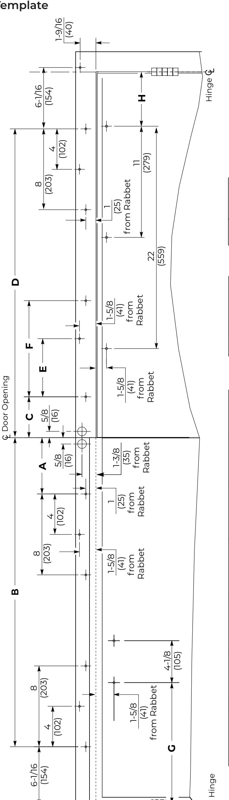
| Model Dim H | DEL 5-3/8 (137) | DELI 7-3/4 (197) | 7 1 1 1 1 1 1 1 1 1 1 1 1 1 1 1 1 1 1 1 |
|---|---|---|---|
| Dim G | 13-1/4 (337) | 12-5/8 (320) |
82°
1/2 (292)
7-3/4 (197)
32-9/16 (827) 34-9/16 (878) 36-9/16 (929) 38-9/16 (979)
4-1/16 (103) 4-1/16 (103)
8 (203)
4 (102)
9-1/2 (241)
5-3/4 (146)
30-9/16 (776)
(2.12)(827)
30-9/16
Dim F
Din
Ωi
Dim C
Door Size
36
。 06
Open Angle Door
| · | DEL reveal up to 3 (76) maximum and 110° of ope |
|---|---|
| 605I-1L arm and track for Pull side door and 6061 arm assembly for Push side door |
10-3/4 (273) 11-1/8 (283) 1/2 (292) 12 (305)
.0II
9-1/2 (241)
9-1/2 (241) 9-1/2 (241)
5-3/4 (146) 5-3/4 (146)
(0501) 91/6-04 42-9/16 (1081)
14-1/16 (356) 12-1/16 (306)
1030) (1881)
40-9/16
15-9/16 (395)
13-9/16 (344)
44 46 48
16-1/16 (408)
42-9/16 (
17-9/16 (446)
5-3/4 (146)
100°
9-1/2 (241)
5-3/4 (146)
10-1/16 (256)
36-9/16 38-9/16
11-9/16 (294)
42
9-9/16 (243)
(878)(929)(6.26)
34-9/16 (
(243)
4
32-9/16
7-9/16 (192) 9-9/16
38
105°
• DELI reveal 3 to 4-3/4 (76 to 121) maximum and 110° of opening. 6051-2L arm and track for Pull side door and 6061-1 arm assembly for Push side door. • DEL2 reveal 4-3/4 to 7-3/8 maximum and 100° of opening. 6051-2L arm and track for Pull side door and ening.
6071-1 arm assembly for Push side door
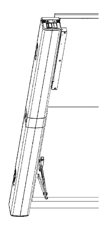
Do not scale drawing. Operator shown for push side double door application. Operator shown for push side double door application. All dimensions are given in inches and millimeters. Recommended thickness for reinforcements in hollow-metal doors and frames should provide a combined material thickness of .164 (4.2) MIN. This template information based upon use of 5 (127) maximum width butt hinges of 3/4 (19) offset pivots.