Norton Rixson 6000 Series Low Energy Operator Onboard or Wi-Fi Smart Device Single Door Programming Instructions_80-9360-1043-020
Open the original PDF document
View PDF6000 Series
Full Feature Low Energy Operator Single Door Installation


Programming Instructions Onboard or Wi-Fi Smart Device
This product can expose you to lead which is known to the state of California to cause cancer and birth defects or other reproductive harm.
For more information go to: www.P65warnings.ca.gov.
Pour la version francaise voir NortonRixson.com. READ AND FOLLOW ALL INSTRUCTIONS. SAVE THESE INSTRUCTIONS.
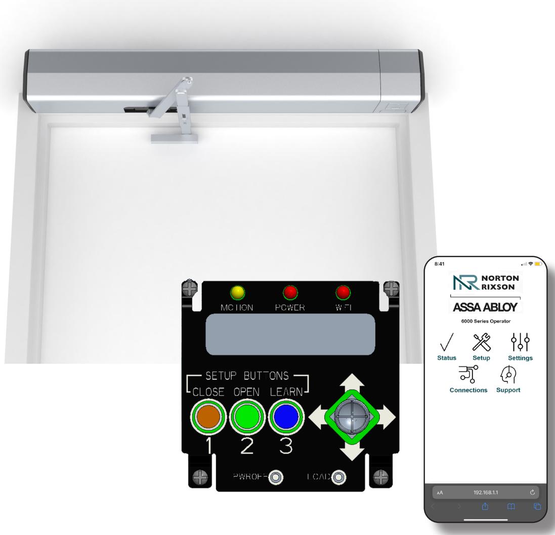
These programming instructions guide setup of the 6000 operator installed on a single door via the onboard LCD screen or a Wi-Fi smart device.

Contents
| Initial Wiring 4 | |
|
Operator Setup via the Control Board
|
5 |
|
Setup via the LCD Screen (cont.)
|
6 |
| Adjust Opening and Closing Position | 7 |
| Setup Options | 8 |
| Operator Setup via Wi-Fi | 9 |
| Application Options 10 | |
| Status | 10 |
| Setup | 10 |
| Application Options (cont.) | 11 |
| Settings | 11 |
| Connections . | 12 |
|
Output Connections (Default)
|
12 |
|
Input Connections (Default)
|
13 |
| Troubleshooting and Support | 14 |
| Support | 14 |
| Status Definitions | 14 |
| Error Codes15 | |
| Updating 6000 Wi-Fi Inverter Firmware | 16 |
| Wiring Diagrams | 17 |
| Basic Single Door Wiring Using Factory Presets 17 | |
| Hard Wired Push Button . | 18 |
| Wave-to-Open | 19 |
| Radio Frequency Standard Function . | 20 |
| 24VDC Fail Secure Electric Strike or Electric Exit Device 21 | |
| 24VDC Fail Safe Electric Strike or Electromagnetic Lock22 | |
| Electric Dogging Exit Device . | 23 |
| MKA2 x 24V Strike | 24 |
| Electric Latch Retraction Exit Device Powered Through 782N Controller | 25 |
| Electric Latch Retraction Exit Device | |
| for Smoke Ventilation - Blow Open Function . | 26 |
| Hard Wired Executive Function27 | |
| Radio Frequency Executive Function | 28 |
| 433MHz Receiver User's Guide . | 29 |
| Vestibule Function30 | |
|
585 Presence Detector on Single Door Opening
|
31 |
| 596 Presence Detector on Single Door Opening | 32 |
| Troubleshooting Guide 33 |
80-9360-1043-020 Rev 3 06/24

FCC:
Class B Equipment
This equipment has been tested and found to comply with the limits for a Class B digital device, pursuant to Part 15 of the FCC Rules. These limits are designed to provide reasonable protection against harmful interference in a residential installation. This equipment generates, uses and can radiate radio frequency energy and, if not installed and used in accordance with the instructions, may cause harmful interference to radio communications. However, there is no guarantee that interference will not occur in a particular installation. If this equipment does cause harmful interference to radio or television reception, which can be determined by turning the equipment off and on, the use is encouraged to try to correct the interference by one or more of the following measures:
- Reorient or relocate the receiving antenna.
- Increase the separation between the equipment and receiver.
- Connect the equipment into an outlet on a circuit different from that to which the receiver is connected.
- Consult the dealer or an experienced radio/TV technician for help.
This device complies with Part 15 of the FCC Rules. Operation is subject to the following two conditions: (1) This device may not cause harmful interference, and (2) this device must accept any interference received, including interference that may cause undesired operation.
Warning:
Changes or modifications to this device may void the user's authority to operate the equipment.
Industry Canada:
This Class A digital apparatus meets all requirements of the Canadian Interference Causing Equipment Regulations.
Cet appareillage numérique de la classe A répond à toutes les exigences de l'interférence canadienne causant des règlements d'équipement.
Declaración de México:
La operación de este equipo está sujeta a las siguientes dos condiciones: (1) es posible que este equipo o dispositivo no cause interferencia perjudicial y (2) este equipo o dispositivo debe aceptar cualquier interferencia, incluyendo la que pueda causar su operación no deseada.
Initial Wiring
- With building power feed turned off, route 120VAC wiring through the conduit holes in the back plate (for concealed wiring) or through the Union Assembly knock-out (for surface wiring) and connect the conduit to the Conduit Assembly.
-
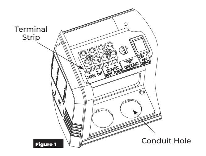
2. Connect 120VAC power to the terminal strip on top of the Conduit Assembly (Figure 1):
- HOT to "+"
- NEUTRAL to "-"
- GROUND to the green ground screw.
NOTE: The Union Assembly may have to be removed for ease of access. Remove AND SAVE the (4) 8-32 x 5/16" Philips pan head screws.
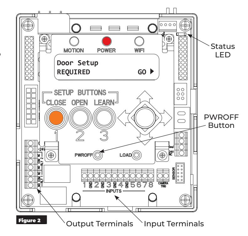
- Wire any additional output devices, such as electric strikes, mag locks, exit devices, door open position output, etc., to the green terminals on top of control board. (Figure 2)
- 4. If applicable, reinstall the Union Assembly using the (4) 8-32x5/16" screws previously removed.
- 5. Turn on the building power to unit.
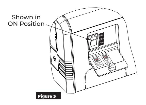
- 6. Confirm the ON/OFF/HO switch, located in the end cap, is in the ON position before proceeding to Setup (Figure 3).
Once power is applied and the switch is set to "ON":
- The red POWER LED on the control board will be on steady red, indicating power is applied. If the POWER LED is flashing, refer to Troubleshooting section of this manual or contact Technical Product Support.
- The white Status LED flashes every 1.5 2 seconds.
- The CLOSE button of the Setup Buttons will be flashing orange continuously.
- The "Door Setup REQUIRED" menu will be displayed on the LCD.
NOTE: If the LCD displays "Door Setup COMPLETE", when power is first applied, a reset of the control board is required. To reset the control board , press and hold the PWROFF button until the LEDs flash, and then release. Once the reset is complete, the LCD will display "Door Setup REQUIRED".
The operator is now powered and ready for setup.
To perform operator setup, proceed to: Operator Setup via the Control Board on page 5 or Operator Setup via Wi-Fi on page 9

WARNING: Door may begin to move immediately when selector mode switch is changed. An open union assembly door has potential to pinch fingers if the hand is not withdrawn quickly when adjusting selector mode switch. Potential damage could occur if the door is open during closing cycle of a pull side assembly.

Operator Setup via the Control Board
After the operator has been successfully installed and power has been applied (refer to Initial Wiring on page 4), follow the steps below to setup the operator via the Control Board.
A. Select Arm Type:
- 1. On the Door Setup REQUIRED menu, select "GO" by pushing the joystick to the right. (Figure 4)
- 2. Move the joystick to the RIGHT or LEFT and select PUSH or PULL to set the arm type, depending on the application. (Figure 5)
NOTE: If unsure, refer to the installation documents provided with the product to determine application type.
C. Select Operator Model:
- 1. After the arm type has been selected, push the joystick UP to select the operator model. (Figure 6)
- 2. Select the specific operator model by pushing the joystick to the LEFT or RIGHT.
PULL (Figure 7)
- ‒ 6011 PULL 110°
- ‒ 6051 PULL 110°
PUSH (Figure 8 or Figure 9)
- ‒ 6021 PUSH 110°
- ‒ 6031 PUSH 110°
- ‒ 6061 PUSH 85°
- ‒ 6061 PUSH 90°
- ‒ 6061 PUSH 95°
- ‒ 6061 PUSH 100°
- ‒ 6061 PUSH 105°
- ‒ 6061 PUSH 110°
- ‒ 6071 PUSH 85°
- ‒ 6071 PUSH 90°
- ‒ 6071 PUSH 95°
- ‒ 6071 PUSH 100° ‒ 6071 PUSH 105°
- ‒ 6071 PUSH 110°
- 3. Once the specific operator has been selected, push the joystick UP.
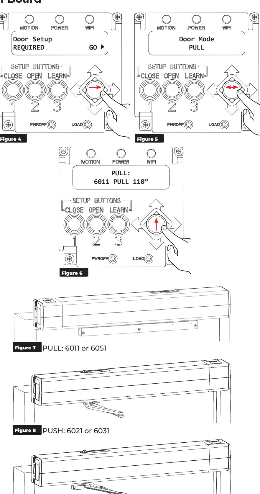
Figure 9 PUSH: 6061 or 6071

Setup via the LCD Screen (cont.)
D. Set the door open and closed positions.
Set the closed position:
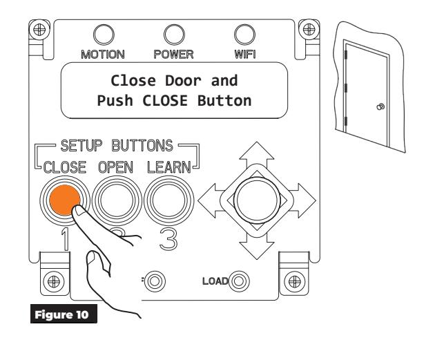
- 1. Fully close the door.
-
2. Press and released the CLOSE button on the control board.
- ‒ The orange CLOSE LED will change from flashing to on solid.
- ‒ The green OPEN LED will begin flashing.
NOTE: Whenever the door is in the closed position, the orange LED of the CLOSED button will be on solid.
Set the open position:
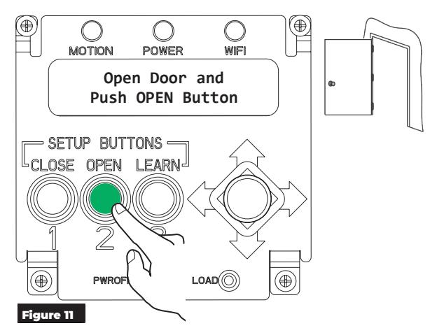
- 1. Manually hold the door in the fully open position. NOTE: If there is a wall or door stop at the open position, hold the door slightly away from the wall or stop.
-
2. Press and release the OPEN button on the control board.
- ‒ The OPEN button's green LED will change from flashing to on steady.
NOTES:
- y Whenever the door is in the open position, the green LED of the OPEN button will be on solid.
- y If open position is not set within 30 seconds of setting closed position, closed position must set again.
- 3. Manually close the door.
Initiate the operator Learn Mode:
Before initiating the LEARN function , confirm there are no obstructions or latching hardware that can prevent the door from opening.
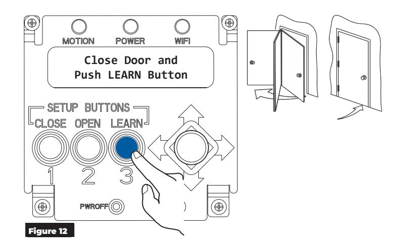
-
1. Press and release the LEARN button on the control board.
- ‒ The blue LEARN LED will begin to flash.
- ‒ The door will start opening in small increments.
- 2. Allow the door to open and close without interference.
NOTE: After the operator has completed the LEARN function, any spring adjustments, additional hardware, or accessories added to the door that changes the weight of the door will require this step be repeated.
Once the LEARN function has been completed, the operator can be adjusted to gain up to an additional 5° of opening using the Open Pos Adjust Setting menu. Refer to Adjust Opening and Closing Position on page 7

Adjust Opening and Closing Position
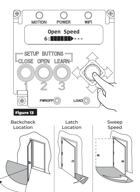
A. Access the Open Pos Adjust menu.
Use the joystick to scroll through and adjust the electrical settings for opening and closing the door. (Figure 13).
For a list of options, refer to Setup Options on page 8.
NOTE: Latch, Sweep, and Backcheck valves are adjusted during the initial installation. Refer to the installation instructions provided with the operator.

Speed/Force and Timing/Location settings must be adjusted to meet ANSI BHMA A159.19 (American National Standard for Power Operated Doors) requirements for opening and closing based on door weight and width. Refer to the information below.
| Table I |
|---|
|
Minimum Opening Time to Backcheck or 80° (whichever occurs first) and
Minimum Closing Time from 90° to Latch or 10° (whichever occurs first) |
| "D" | "W" Door Weight in Pounds (kg) | ||||
|---|---|---|---|---|---|
|
Door Leaf Width
Inches (mm) |
100 (45.4) | 125 (56.7) | 150 (68.0) | 175 (79.4) | 200 (90.7) |
| *30" (762) | 3.0 sec | 3.0 sec | 3.0 sec | 3.0 sec | 3.5 sec |
| 36" (914) | 3.0 sec | 3.5 sec | 3.5 sec | 4.0 sec | 4.0 sec |
| 42" (1067) | 3.5 sec | 4.0 sec | 4.0 sec | 4.5 sec | 4.5 sec |
| 48" (1219) | 4.0 sec | 4.5 sec | 4.5 sec | 5.0 sec | 5.5 sec |
* Check applicable Building Codes for clear width requirements in the Means of Egress. See Appendix for additional door weights.
| Table II |
|---|
| Total Opening Time to 90° |
| Backcheck at 60° | Backcheck at 70° | Backcheck at 80° | |
|---|---|---|---|
| Table I plus 2 seconds | Table I plus 1.5 seconds | Table I plus 1 second | |
If the door opens more than 90 degrees, it shall continue at the same rate as backcheck speed. Matrix values are in seconds.
NOTE: To determine minimum times from close to full open, the operator shall be adjusted as shown in the chart. Backcheck occurring at a point between positions in Table II shall use the lowest setting. For example, if the backcheck occurs at 75 degrees, the full open shall be the time shown in Table I plus 1.5 seconds.
Doors of other weights and widths can be calculated using the formula:
T = D√W / 133 in US Units T = D√W / 2260 in SI (metric) Units
Where: T = Time, seconds
D = Door width, inches (mm) W = Door weight, lbs. (kg)
The values for "T" (time) have been rounded up to the nearest half second. These values are based on a kinetic energy of 1.25 lbf-ft (1,86 kg/m).

Setup Options
The following setup options are available on the Open Pos Adjust Setting menu. The the joystick to select each option and set the values. (Figure 14)
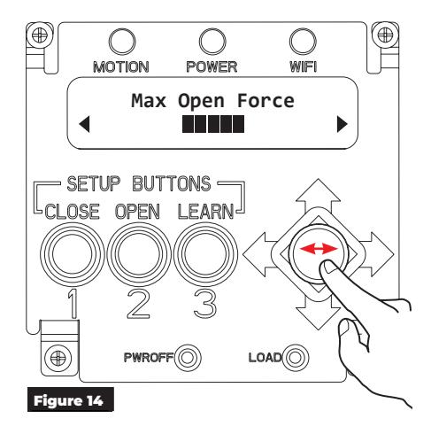
y OPEN SPEED:
Speed at which the door opens.
y MAX OPEN FORCE:
Force exerted by the motor to open the door.
y OPEN POSITION ADJUST:
Once the open position has been set, the door can be adjusted +/- 5° without having to rehome the unit.
y OPEN START FORCE:
Force exerted by the motor at the start of the opening cycle to help overcome stack pressure or latch device.
y OPEN STALL FORCE:
Force exerted when the door is slowed to a stop while opening, with 1 being lightest and 10 being strongest. Measure the door force to ensure compliance with applicable standards and codes.
y ADJUST HOLD OPEN:
Time the door is held at the open position when ON/OFF/ HO switch is in ON position.
y HOLD OPEN FORCE:
Force exerted to hold the door in the max open position. This can be adjusted to overcome stack pressure, wind, or other forces pushing on the door.
y OBST DET SENS:
Amount of time the door will push against an obstruction before stalling or moving in the opposite direction.
y OPEN DELAY 1:
Time before the door begins to open once activation has been received.
y OPEN DELAY 2:
Time before door begins to open once activation has been received. Part of Vestibule functionality.
y PUSH & GO:
As the door is manually opened, the operator 'senses' movement and opens the door to the fullopen position.
y OBSTR DURING CLOSE:
Door will reverse to the open position if it hits an obstruction while closing.
y NO OBSTR NEAR OPEN:
Used with the door mounted presence sensor. The operator will ignore an obstruction input from the sensor in last 30 degrees of opening.
y NO OBSTR NEAR CLOSE:
Used with the door mounted presence sensor. The operator will ignore an obstruction input from the sensor in last 10 degrees of closing.
y ENERGIZE <20°:
24V outputs will change state when the door is 20 degrees from close after a manual or automatic cycle.
Initial Operator setup is now complete. Continue setup with "Connections" on page 12.

ASSA ABLOY
Operator Setup via Wi-Fi
After the operator has been successfully installed and power has been applied (refer to Initial Wiring on page 4), follow the steps below to setup the operator via Wi-Fi.
A. Turn on Operator Wi-Fi.
1. With the cover off:
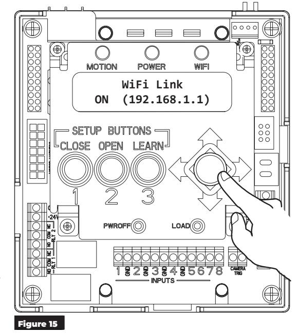
Using the joystick, scroll through the menu options to the WiFi Link menu. (Figure 15)
With the cover on:
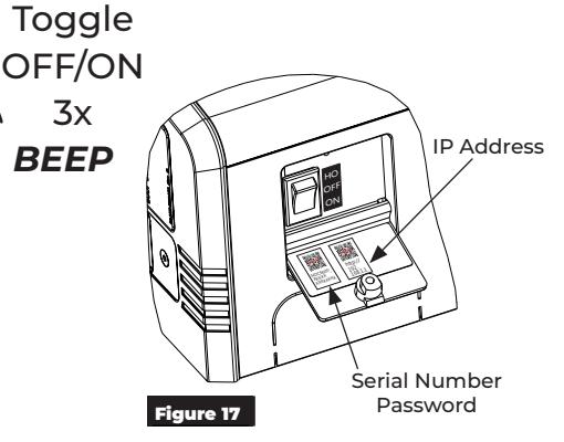
Toggle the 3-position switch located on the end cap three (3) times. (Figure 16)
- The operator will emit a long beep when Wi-Fi has been successfully turned on.
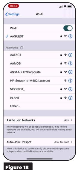
- 2. On a smart device, open the Wi-Fi Networks application.
- 3. Find the associated operator's network (beginning with NDC6000_, followed by the operator's SSID). Once found, connect to the network. (Figure 18)
NOTE: The operator's SSID, Password, and IP Address are located on the inside of the switch-side end cap door. (Figure 17)
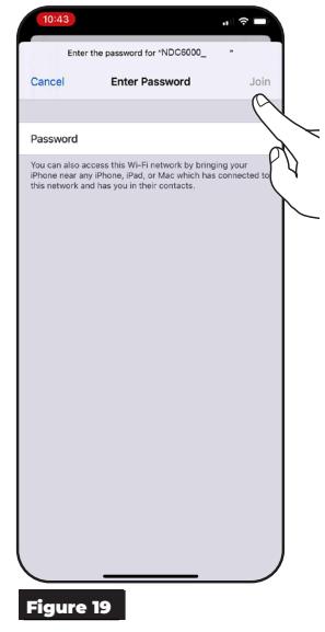
- 4. Enter the operator's password and click "Join". (Figure 19)
-
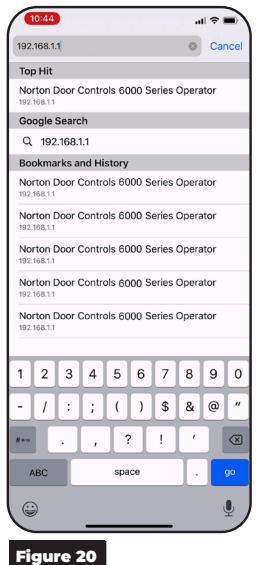
5. Open a web browser and enter 192.168.1.1 into the address bar. (Figure 20)
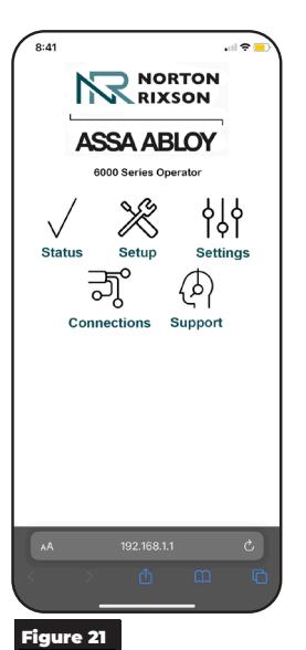
- The 6000 Series homepage will be displayed. (Figure 21)
Wi-Fi connection to the operator has been established.
NOTES:
- Wi-Fi will automatically turn off after 20 minutes of inactivity.
- Wi-Fi can be manually turned off by selecting OFF on the LCD screen or toggling the 3-position switch again.
- The operator will emit a short beep indicating that Wi-Fi has been turned off.
Shown in ON Position
3x
Experience a safer and more open world

Application Options
Status
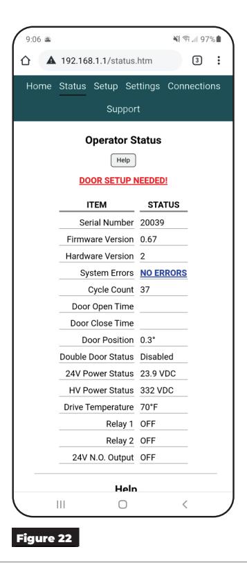
Use the Status page to quickly access important information about the operator. (Figure 22)
NOTE: "Door Setup Needed" will be displayed if door setup has not been completed.
Setup
To set up the operator, select the Setup tab and perform the following steps.
- 1. Use the drop down menu of Step 1 to select the operator model, hand, and opening range that matches the operator installation. (Figure 23)
- 1. Manually close the door and select "Set Closed Position" in Step 2. (Figure 23)
- 2. Open door to the fully open position. Holding the door in this position, select "Set Open Position" in Step 3. (Figure 24)
- 3. Manually close the door and select "Learn" in Step 4 to initiate the Learn process. (Figure 24)
NOTE: Before initiating the LEARN function , confirm there are no obstructions or latching hardware that can prevent the door from opening.
4. Refresh the browser page to confirm all steps have a check mark, indicating the operator setup has been successful.
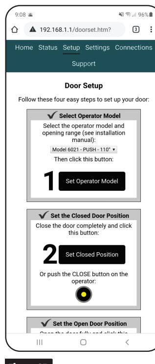
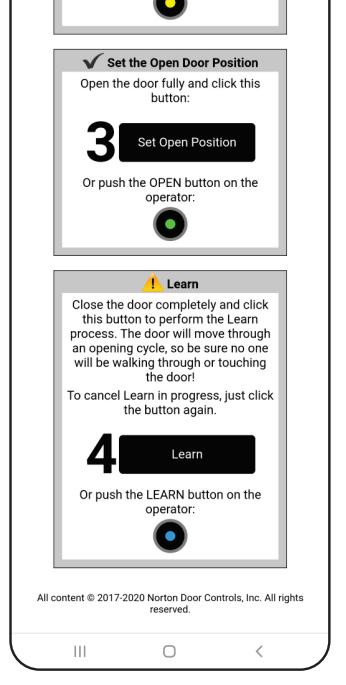
Figure 23 Figure 24

Application Options (cont.)
Settings
NOTE: The Double Door tab is reserved for the 6000 Series Double Door installation. Refer to Document 80-9360-1049-020 for Double Door Programming Instructions.
Speed/Force and Timing/Location :
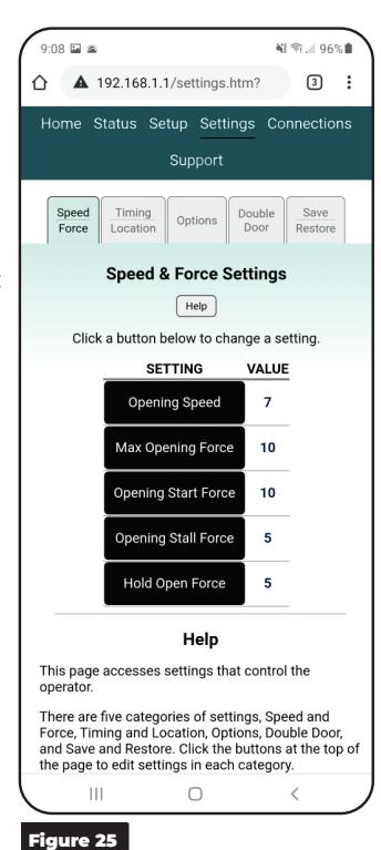
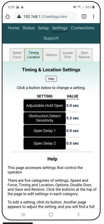
Speed/Force and Time/Location settings can be adjusted to meet BHMA requirements. (Figure 25 and Figure 26)
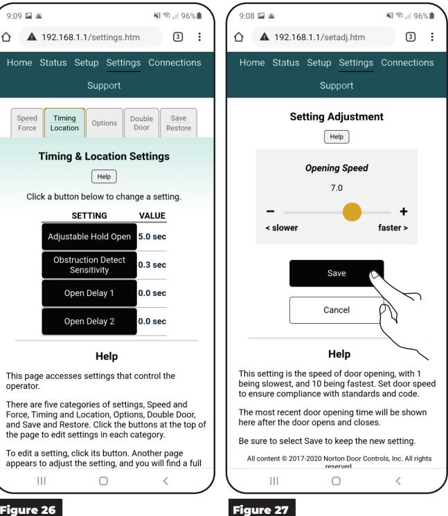
Select each setting and adjust slider or press -/+ to desired value, then save. (Figure 27)

Speed/Force and Timing/Location settings must be adjusted to meet ANSI BHMA A159.19 (American National Standard for Power Assist and Low Energy Power Operated Doors) requirements for opening and closing based on door weight and width. (Refer to Table I and Table II on page 7)
Options:
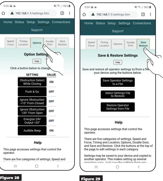
Select each setting to change the option for the operator, and then save. (Figure 28)
Save/Restore:
Use this tab to save the operator settings to a file, transfer previously saved settings to another operator, or restore an operator to saved settings. (Figure 29)
- y Save Operator Settings to a File : Click this button to save the operator's current settings to a file.
- y Select Setting Files to Restore : Click this button to choose a saved file to load to an operator.
- y Restore Operator Settings from File : This option will be grayed out an unavailable until a connection to an operator has been established (refer to Operator Setup via Wi-Fi on page 9) and a file has been selected. Once available, clock this button to load the file selected to the receiving operator.

Initial Operator setup is now complete. Continue setup with "Connections" on page 12.
Connections
Operator inputs and outputs can be customized.
NOTE: Input and Outputs numbers are labeled on the control board. Refer to Figure 2 on page 4.
To customize the inputs and outputs via the operator control board : Scroll through the menu settings and set each input and relay function. Use the joystick to scroll through each setting option.
To customize the inputs and outputs via the Wi-Fi application: On the Connections page, select the input or output then scroll through drop-down menu to select the desired function for each. (Figure 30 and Figure 31) or the operator's control board.
NOTE: For definitions, see Output Connections below and Input Connections on page 14.
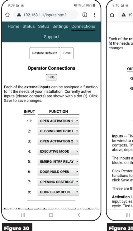

Output Connections (Default)
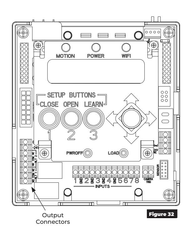
Use the green 2-position connectors on the control board to add any necessary outputs, such as electric strikes, mag locks, exit devices, door open position output, etc. (Figure 32)
NOTE: Relay outputs can be customized.
Relay Outputs
- ‒ The operator has two relay outputs which may be wired to external control systems or devices. The function of each relay is selectable depending on the needs of the installation.
- ‒ Outputs are labeled RLY 1 and RLY 2 like the wiring terminal blocks on the operator hardware.
- ‒ Click Restore Defaults to set the input and output functions to factory default, if needed. Be sure to click Save after making changes.
Relay Output Functions:
3 Second Relay
Normally open relay that closes for 3 seconds after an activation to open.
Open POS Relay
Normally open relay that closes when door is in open position.
Closed POS Relay
Normally open relay that closes when door is in closed position.
Door Latch Relay
Normally open relay that closes any time door is not in closed position.

Input Connections (Default)
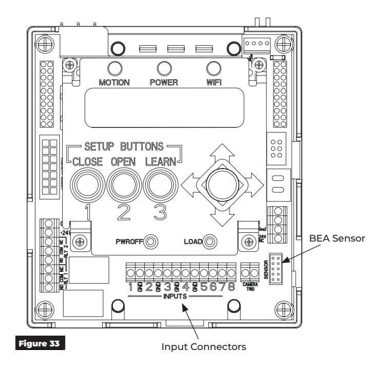
Use the green 2-position connectors on the control board to install any necessary inputs. (Figure 33)
NOTE: Inputs can be customized. The operator has several inputs which can be wired to external switches, sensors, or dry contacts. The function of each input is selectable depending on the installation.
To restore the operator inputs to factory defaults, select Restore Defaults.
Activation 1
Momentary contact closure of this input cycles the door through an automatic open / close cycle. (Tied to Open Delay 1)
Activation 2
Momentary contact closure of this input cycles the door through an automatic open / close cycle. (Tied to Open Delay 2)
Executive Mode
Activation signal on this input opens the door keeps it open until either a second signal is received or the door is manually moved in closing direction.
Emergency Interface Relay
Continuous contact closure of this input puts operator in a passive closer mode, where door functions as a typical door closer and accepts no activations. Once contact is removed, unit goes back to operator mode.
Blow Open
If 3-Position switch is in On position, the door opens when signal is received from alarm system allowing air or smoke to flow through opening. The door will stay open until signal from alarm system is stopped. If the door is pulled away from open position, operator will go back to open.
Blow Open Override
With 3-Position switch in On or Off position, the door opens at set position until power is turned off.
Obstruction 1
Contact closure of this input while door is closing triggers operator to return to open position. This is used with presence sensors mounted to closing side of a door to prevent door from hitting an obstruction.
Obstruction 2
Contact closure of this input while door is opening triggers operator to stall. If contact is not removed after 10 seconds of closure, operator will return to closed position. This is used with presence sensors mounted to opening side of a door to prevent door from hitting an obstruction.
Outside Push Button Disable
When this contact is closed, the outside push button is disabled (connected to ACTIVATION 2 inputs(s)).
BEA 585 Presence Sensor
A BEA type 585 presence sensor may be connected to the "SENSOR" connector on the top circuit board of the operator using cable supplied with sensor. The sensor must be attached to the frame according to the BEA factory instructions and can be powered with a separate power supply or with the power supply built into the 6000 operator. No additional configuration is required. See the installation instructions for more detail.

Troubleshooting and Support
This section provides information to assist in troubleshooting the 6000 Series operator. If additional assistance is needed beyond the information provided here, contact Technical Support.
Support
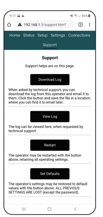
The Support page can be used to restart the operator or restore operator settings to factory defaults. (Figure 31)
Download Log :
The Download Log button allows the user to download a copy of the operator's log file. This file can be used by Technical Support for Troubleshooting assistance.
Click the Download Log button and save the file to a location where it can be easily accessed for email.
View Log :
The View Log button allows the user to view the operator's log file within the application.
Restart :
The Restart button allows the user to restart the operator without changing any existing operator settings.
Set Defaults :
Pressing the Set Defaults button will return the operator to factory settings and initiate a restart. Once pressed, a popup is displayed confirming that a restore will be completed. Press OK to continue or Cancel to keep the current settings.
Status Definitions
During a consultation, Technical support may request status information.
Serial Number :
Each operator has a unique serial number listed on the Status screen or inside the 3-Position switch door (see Figure 14, page 7).
Firmware Version :
This is the version of the control program in the operator. This information is located on the Status menu of the Wi-Fi application or available through the control board menu. .
Hardware Version :
This is the version of the electronic hardware in the operator.
System Errors :
Any errors detected by the operator are listed on the Status screen and Support page with troubleshooting suggestions.
Cycle Count :
This is the number of door open/close cycles that the operator has performed in its life.
Door Open Time :
This is the time it took the door to move from closed to full open position on the last open/close cycle, not including any programmed opening delay. This information is useful when adjusting door speed to comply with code.
Door Close Time :
This is the time it took the door to move from full open position to closed on the last open/close cycle. This information is useful when adjusting door speed to comply with code.
Door Position :
This is the current angular door position in degrees, with the closed position being zero degrees.
Double Door Status :
If the operator is configured for double door operation, the serial number of the connected door appears here.
24V Power Status :
This is the voltage of the 24V DC power source for the operator.
HV Power Status :
This is the voltage of the high voltage DC power source of the operator which runs the motor.
Drive Temperature :
The motor driver temperature is shown here. If the operator has not been in use, this temperature should be near ambient temperature (perhaps higher or lower due to exterior heat or cold). The motor driver heats as the operator is used, and the operator monitors this temperature continuously.
Relay 1 :
This is the state of relay number 1, on or off. The relays may be programmed for various types of operation as the door opens and closes. See the Connections pages.
Relay 2 :
This is the state of relay number 2, on or off. The relays maybe programmed for various types of operation as the door opens and closes. See the Connections page.
24V N.O. Output :
This is the state of the 24V normally open output, on or off. The normally closed output is always in the opposite state.

Error Codes
| Error Codes for RED POWER LED Flashes | |||
|---|---|---|---|
|
Number
of Flashes |
Error | Description | Solution |
| 1 |
Configured Settings
Error |
Configured settings have been lost. | Try restoring factory settings to see if that clears the problem. Set up the operator as needed. |
| 2 | 24VDC Power Error |
Operator 24V power supply is
malfunctioning or there is a wiring problem. |
Make sure all connections are tight. Use a voltmeter to measure power supply output voltage between +V and -V screw terminals. Voltage should be between 23.7V and 24.3V DC with door closed or opening. |
| 3 | Learn Error |
Learn process failed, perhaps
due to an obstruction, faulty hinges, or other mechanical issue. |
Be sure door is in good mechanical working order and retry learn operation. |
| 4 | Motor Error | There is a problem with main motor. | Check all wiring and gently set all connectors on operator, with power off. Power up operator and check operation. |
| 5 |
Over Temperature
Error |
Motor has overheated. | Close door for 15 minutes and check that error subsides as motor cools. |
| 6 | Power Board Error | Power board is not plugged in. | Turn power off and wait 5 minutes. Check that circuit boards in operator are all fastened securely and plugged together per installation instructions. |
| 7 |
Temperature Probe
Error |
Motor temperature probe is disconnected or damaged. | Check all wiring and gently set all connectors on operator, with the power off. Power up operator and check operation. |
| 8 | Sensors Error | Position sensors governing operator are not working correctly. | Turn off and wait 5 minutes. Check that circuit boards in operator are all fastened securely and plugged together per installation instructions. If persists, assure connectors between circuit boards and potentiometers are secured properly. Also assure wires are fully inserted into connectors. |
| 9 | Motor Duration Error | Motor ran longer than allowed. | On/Off switch may be toggled to clear this error or operator may be restarted. |
| 10 | Double Door Error | Cable connecting the two doors is disconnected or damaged. | If this is only a single door, be sure it is set as a single door. If this is a door in a double door pair, be sure sync cable between doors is connected securely. |

Updating 6000 Wi-Fi Inverter Firmware
- 1. Copy the updated .BIN file to a USB drive.
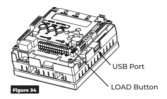
- 2. Insert the USB drive into the USB port on side of the inverter. (Figure 34)
-
3. Press and hold the LOAD button for 3 seconds and release when all LEDs light up. (Figure 34)
- ‒ WARNING screens will be displayed.
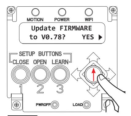
- 4. Once the Warnings have stopped, press up on the joystick to scroll to the Update FIRMWARE screen. (Figure 35)
-
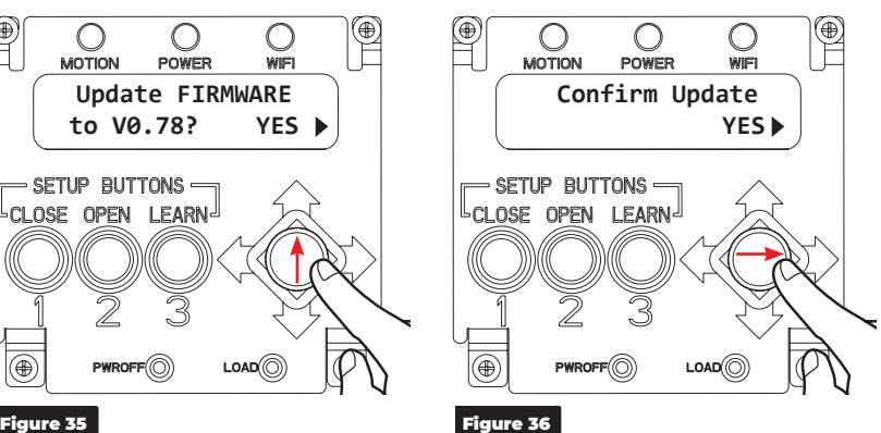
5. Press the joystick right to select Yes.
- ‒ The Confirm Update screen will be displayed.
-
6. Confirm the update by pressing joystick to the right. (Figure 36)
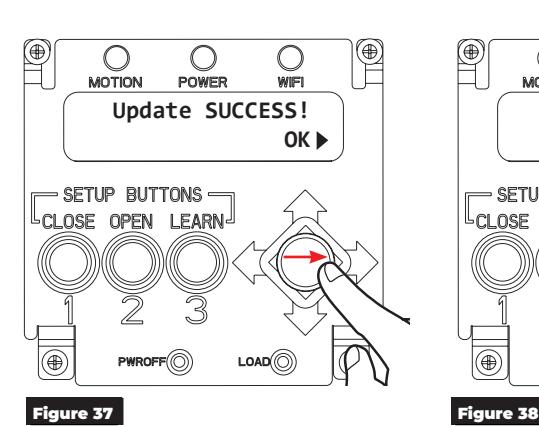
- ‒ Once the update has been completed, "Update SUCCESS!" will appear on screen.
- 7. Press the joystick to the right to continue. (Figure 37)
- 8. Remove the USB from the port.
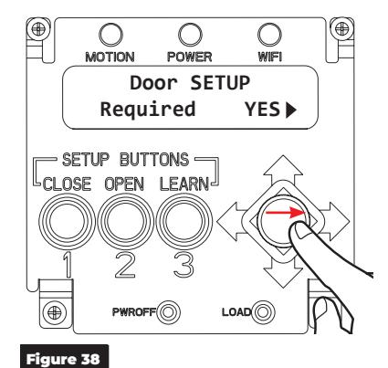
Once the inverter has updated, the screen will power off and back on. The unit is now ready for any additional adjustments. (Figure 38)
NOTE: Door setup may be required following an inverter update. Refer to "Operator Setup via the Control Board" on page 5 or "Operator Setup via Wi-Fi" on page 9

Wiring Diagrams
Basic Single Door Wiring Using Factory Presets
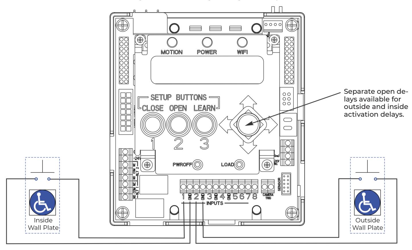
- y The door is normally closed.
- y Activating either switch will open the door. The door will close after the hold open time delay has expired.
- y Separate open delays are available for outside and inside activation delay.
- y Activation can be a wall switch, card reader, key switch, etc (Normally open momentary dry contacts).
17

Hard Wired Push Button
Factory Pre-Wiring Not Required to Change
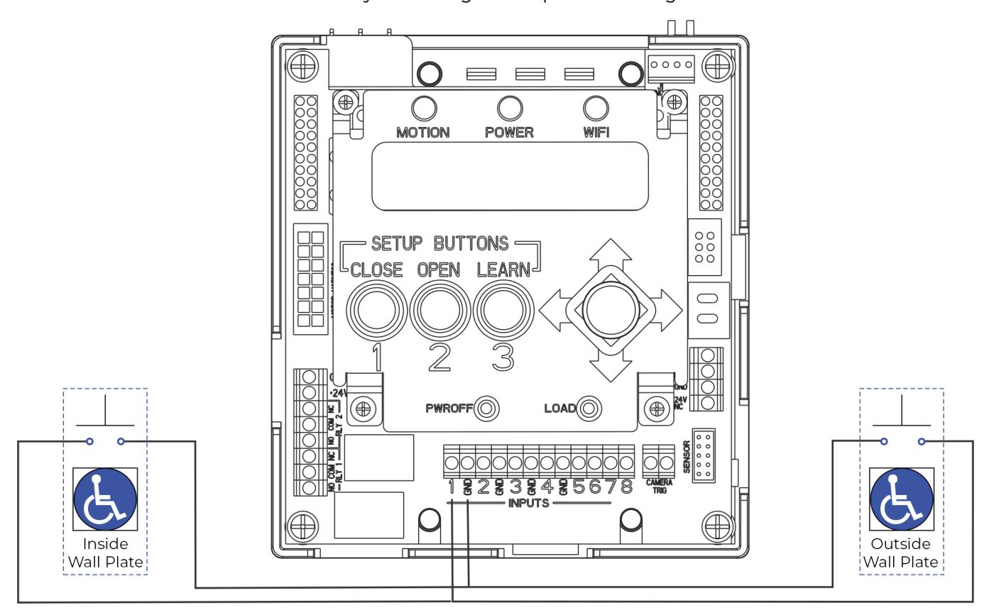
- y The door is normally closed.
- y Activating either switch will open door.
- y The door will remain in indefinite hold open until either switch is activated a second time causing door to close.

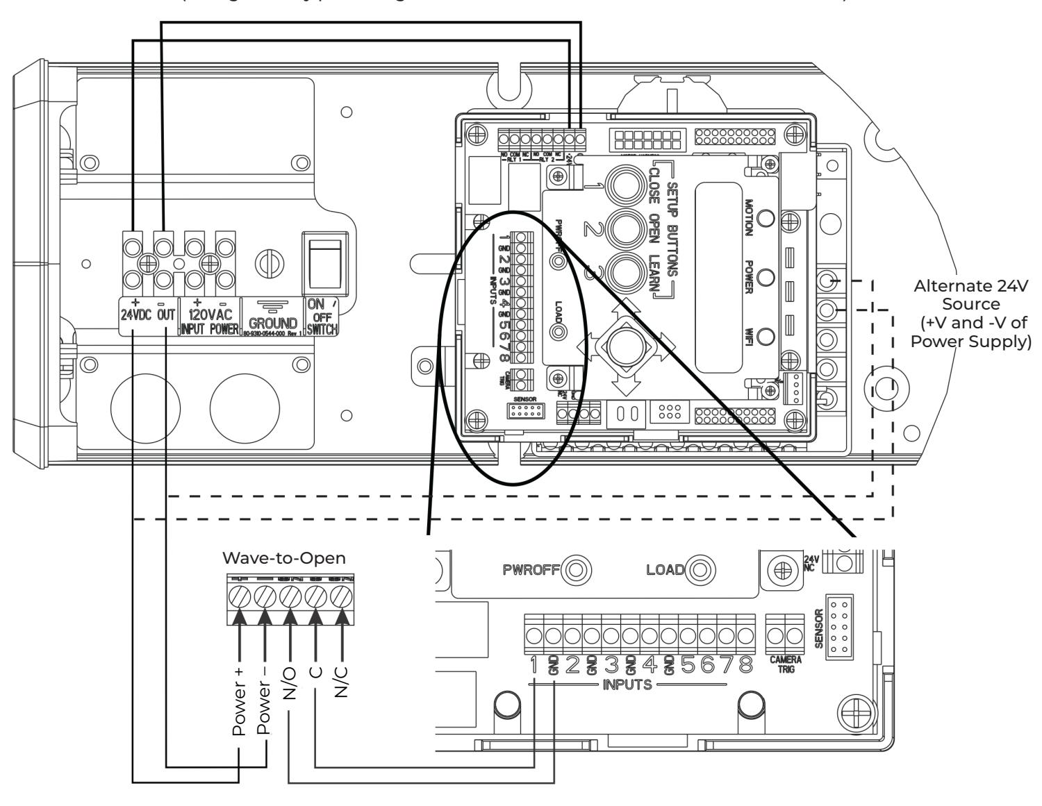
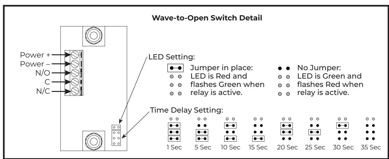
Wave-to-Open
(change factory pre-wiring to illustration below - move NO to +24 on controller)

Radio Frequency Standard Function
(change factory pre-wiring to illustration below - move NO to +24)
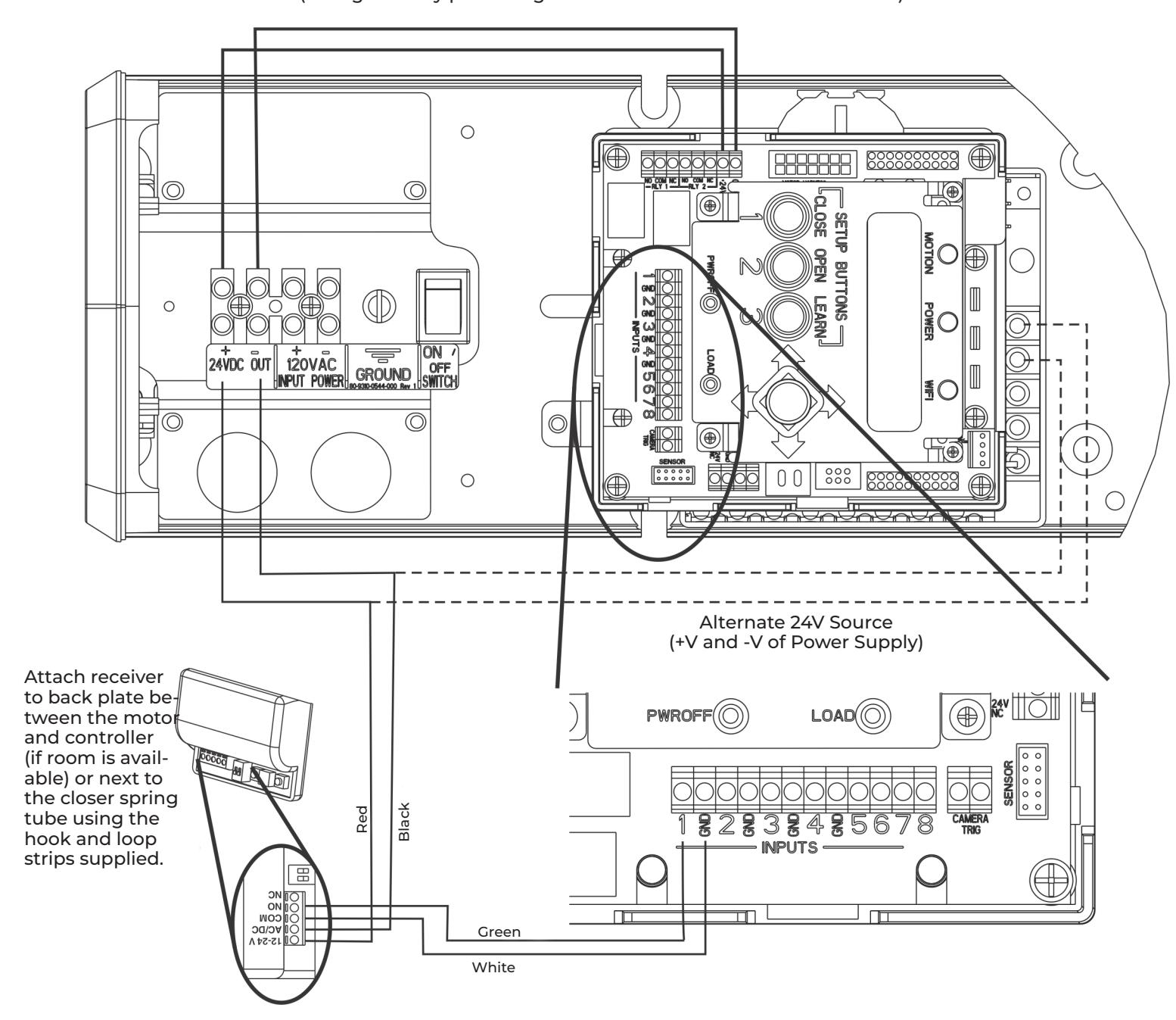
- y The door is normally closed.
- y Activating a wireless switch or hand held wireless transmitter will open the door. The door will close after the hold open time delay has expired.
- y Current draw at the power outputs not to exceed 1.3A.

24VDC Fail Secure Electric Strike or Electric Exit Device
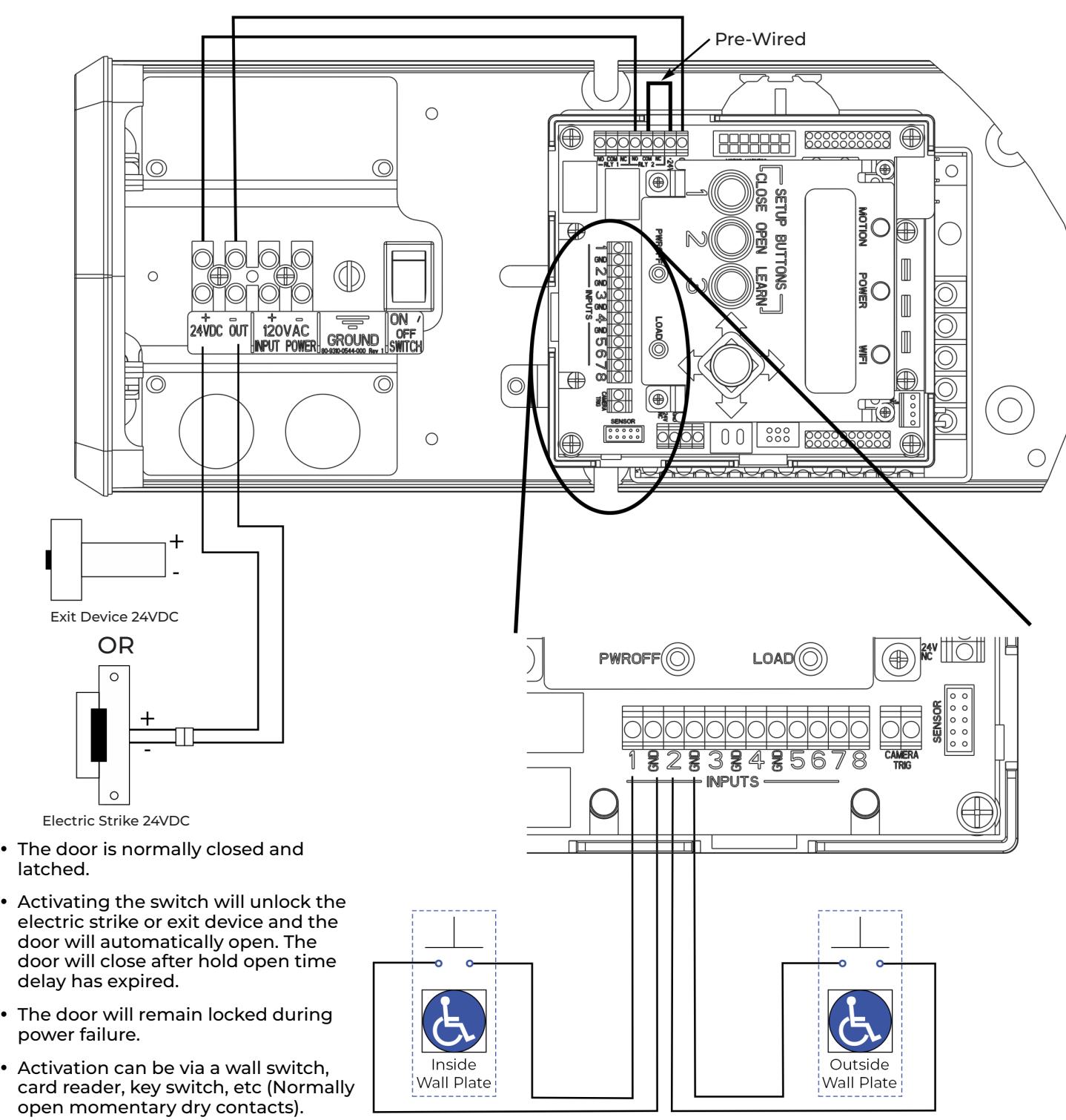
Latch Retraction (Refer to Output Connections on page 12) and/or Open Delay (Refer to Setup options on page 8), each feature must be turned on using adjustment procedures.
y To turn on the relay (Relay 2),
21

24VDC Fail Safe Electric Strike or Electromagnetic Lock
(change factory pre-wiring to illustration below - move NO to NC on controller)
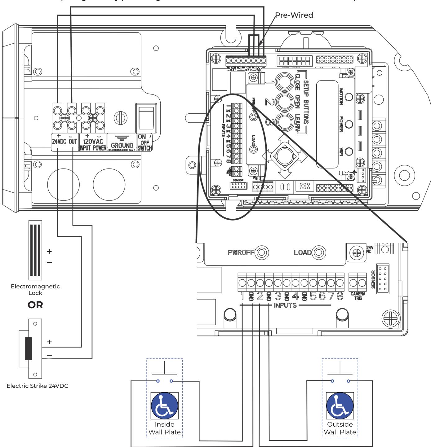
- y The door is normally closed and latched.
- y Activating the switch will unlock the electric strike or mag lock and the door will open automatically. The door will close after the hold open time delay has expired.
- y The door will remain unlocked during a power failure.
- y Activation can be a wall switch, card reader, key switch, etc (Normally open momentary dry contacts).
- y Current draw at the Power Outputs not to exceed 1.3A.
- y To turn on the relay (Relay 2), Latch Retraction (Refer to Output Connections on page 12) and/or Open Delay (Refer to Setup options on page 8), each feature must be turned on using adjustment procedures.

Electric Dogging Exit Device
(change factory pre-wiring to illustration below - move NO to +24)
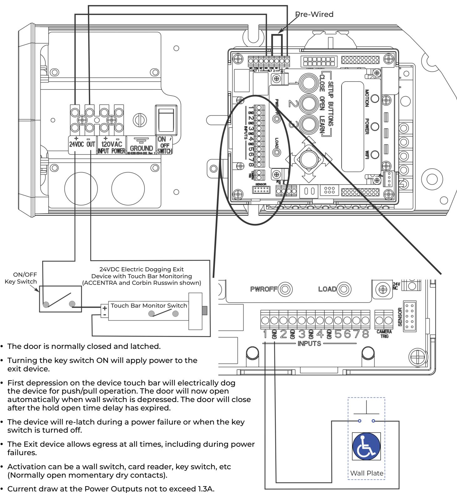
- y To turn on the relay (Relay 2), Latch Retraction (Refer to Output Connections on page 12) and/or Open Delay (Refer to Setup options on page 8), each feature must be turned on using adjustment procedures.

MKA2 x 24V Strike
(change factory pre-wiring to illustration below - move NO to +24)
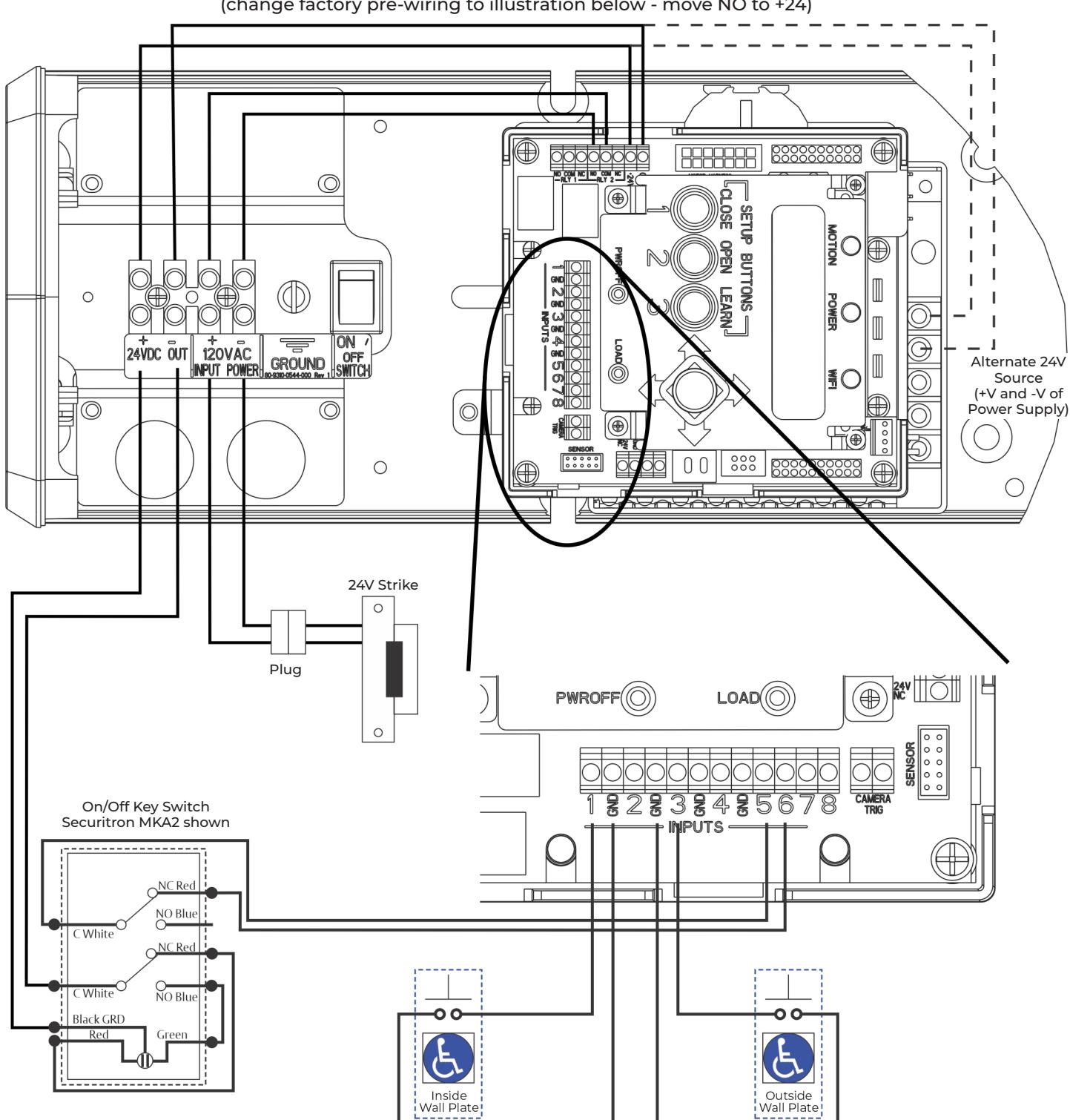
Input 9: Security Override
Continuous contact closure of this input triggers the operator to disable Input 2 / Activation 2.
This is typically used for switching off an outside wall plate.
- y MKA2 shown is in the Normally Closed position, which has LED RED and Exterior Wall Switch disabled.
- y To turn on the relay (Relay 2), Latch Retraction (Refer to Output Connections on page 12) and/or Open Delay (Refer to Setup options on page 8), each feature must be turned on using adjustment procedures.
24

Electric Latch Retraction Exit Device Powered Through 782N Controller
(change factory pre-wiring to illustration below - move GND to COM)
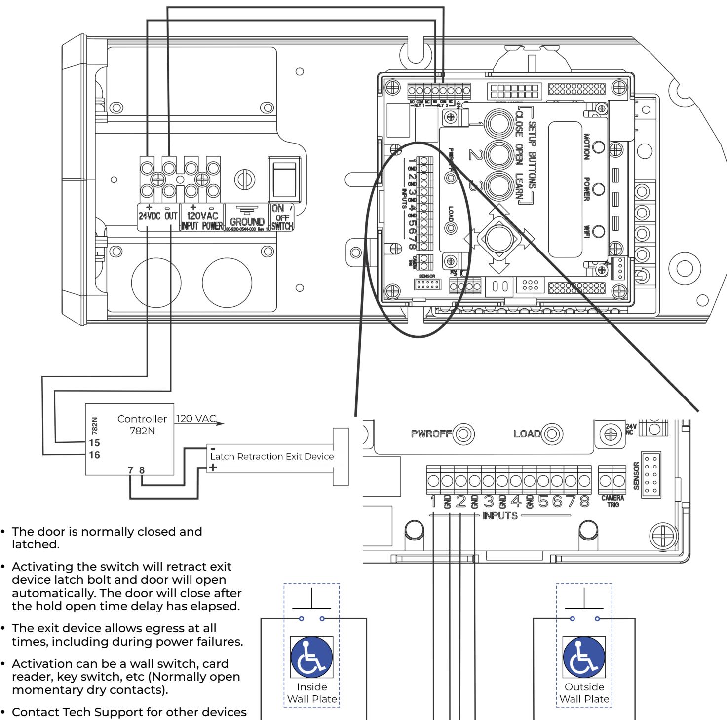
- y Activation can be a wall switch, card
- y Contact Tech Support for other devices or manufacturer's instructions.
- y To turn on the relay (Relay 2), Latch Retraction (Refer to Output Connections on page 12) and/or Open Delay (Refer to Setup options on page 8), each feature must be turned on using adjustment procedures.

Electric Latch Retraction Exit Device for Smoke Ventilation - Blow Open Function
(change factory pre-wiring to illustration below - move GND to COM)
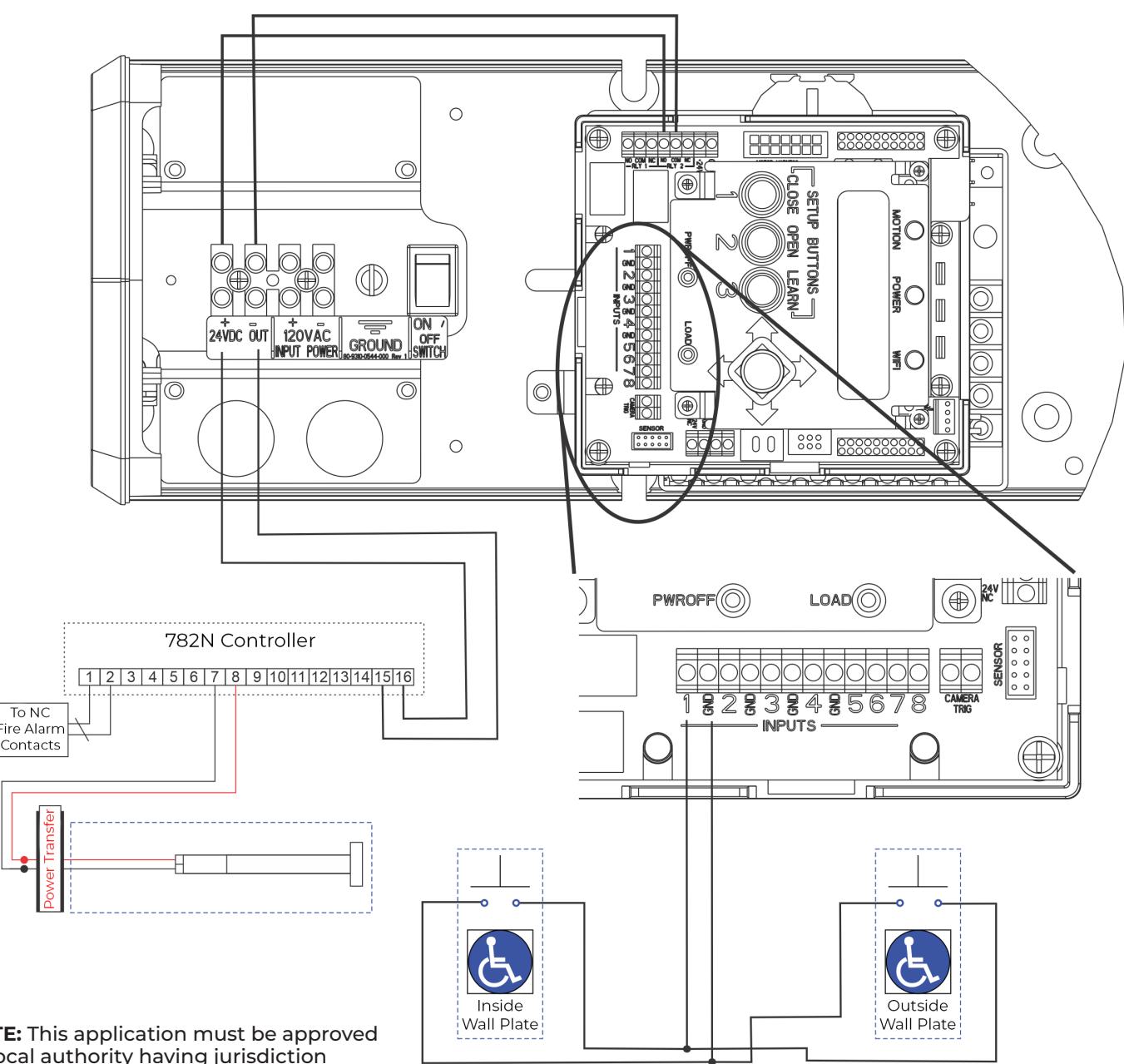
NOTE: This application must be approved by local authority having jurisdiction (AHJ).
- y The door is normally closed and latched.
- y A Fire Alarm activation will retract the exit device latch bolt and the door will open automatically. The door will remain open until the Fire Alarm System has been reset.
- y The door operator's main power input must be wired into the building's backup power supply.
- y The exit device allows egress at all times, including during power failures.
- y Activation can be a wall switch, card reader, key switch, etc (Normally open momentary dry contacts).
- y If the 3-position switch is in the Off position and the Input is set to Blow Open, when signal is received from Fire Alarm System, the door WILL NOT open.
- y If the 3-position switch is in the On position, the door will open when a signal is received from the Fire Alarm System.
- y If the Input is set to Blow Open Override, the door WILL open when a signal is received from the Fire Alarm System if the 3-position switch is in the On or Off position.
- y To turn on relay (Relay 2), Latch Retraction (Output Connections, page 14) and/or Open Delay (Set options, page 8) features must be turned on using adjustment procedures on pages indicated.

Hard Wired Executive Function
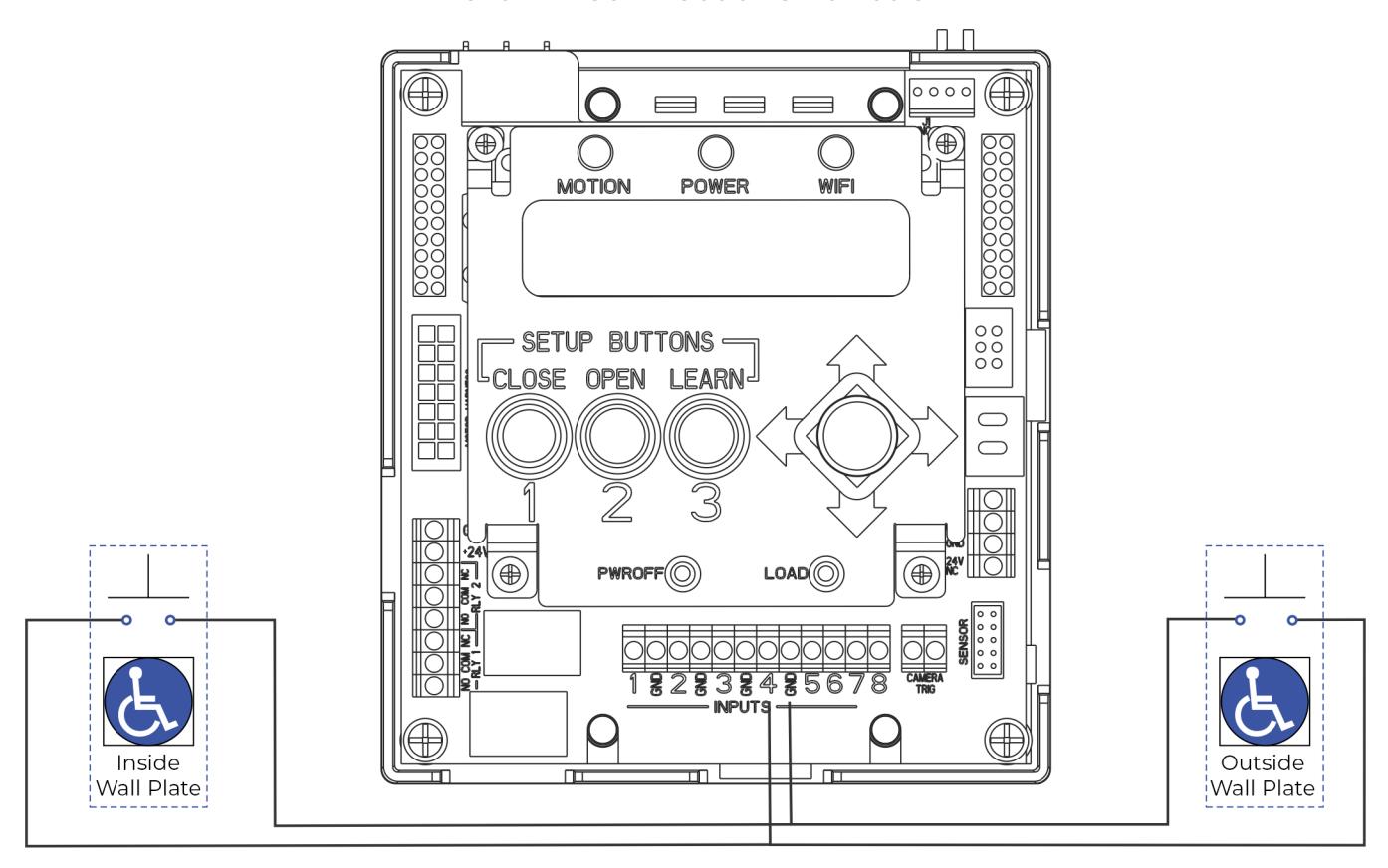
- y The door is normally closed.
- y Activating either switch will open the door. The door will remain in indefinite hold open until either switch is activated a second time causing door to close.

Radio Frequency Executive Function
(change factory pre-wiring to illustration below - move NO to +24)
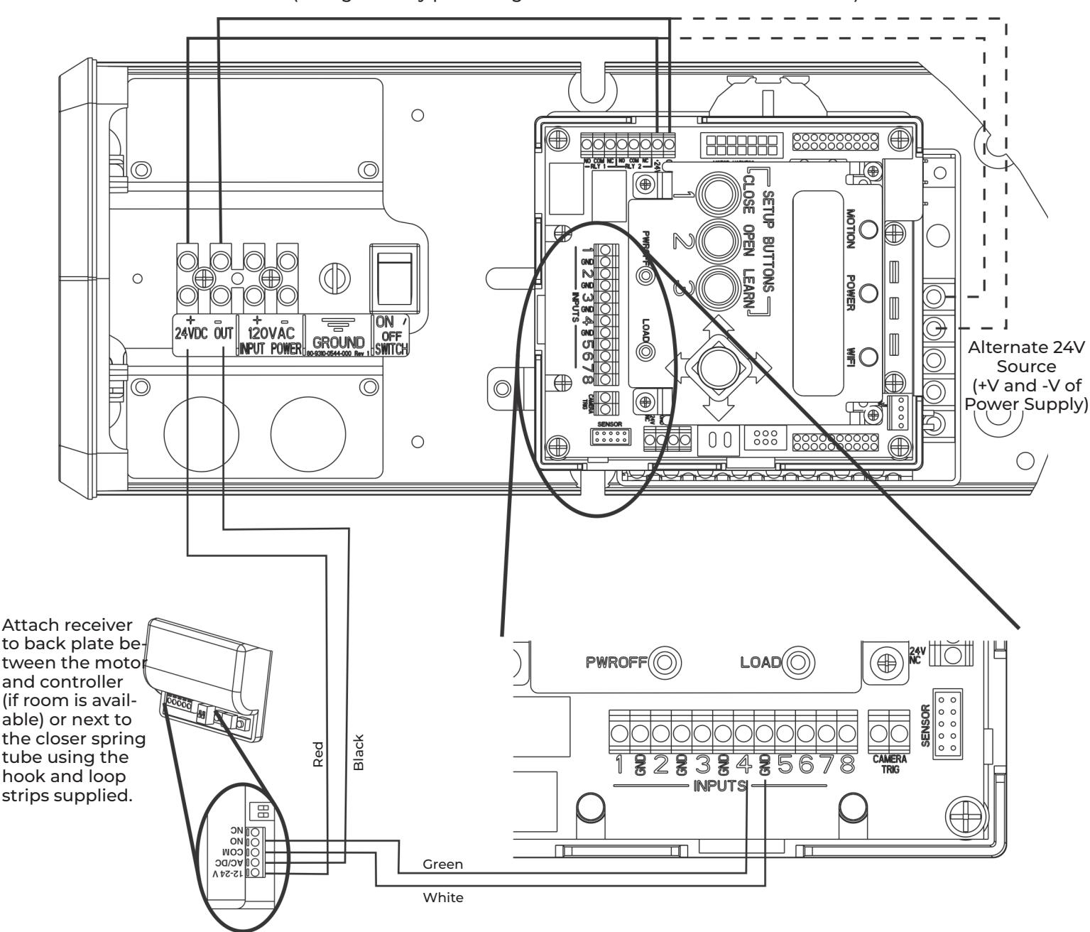
- y The door is normally closed.
- y Activating the wireless switch or hand held wireless transmitter will open the door. The door will remain in indefinite hold open until the wireless switch or hand held transmitter is activated a second time causing the door to close.
- y Current draw at the power outputs not to exceed 1.3A.

433MHz Receiver User's Guide
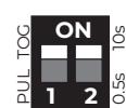
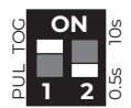
In Toggle Setting (1-ON), Hold Time is inactive. Either setting for #2 dip switch will have same result.
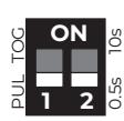
0.5 second Pulse Setting
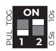
10 second Pulse Setting
| #1 | Description | Function | |
|---|---|---|---|
| OFF |
Press transmitter once and relay will be active
Pulse Relay momentarily. |
||
| ON | Toggle Relay |
Press transmitter once and relay output is active
indefinitely. Press it again and relay will de-energize indefinitely. |
|
|
#2
Description |
Function | |
|---|---|---|
| OFF |
0.5s Hold Time
Relay will remain active 0.5 sec after loss of activation. |
|
| ON | 10s Hold Time | Relay will remain active 10 sec after loss of activation. |
NOTES:
- y Always stop pedestrian traffic through the doorway when performing tests that may result in unexpected reactions by the door.
- y Ensure compliance with all applicable safety standards upon completion of the installation.
- y See diagrams on page 20 for wire colors.
Hand-Held Configuration
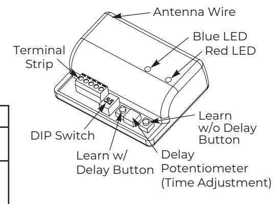
- 1. Set the dip switches on the receiver to the desired activation cycle (dip switch 1 - Toggle or Pulse and dip switch 2 - 0.5s or 10s hold).
-
2. Press either the Learn w/ Delay Button or the Learn w/o Delay Button on the receiver, depending on activation requirements (if delay learn is selected, adjust the delay potentiometer to the counterclockwise limit, 0 second delay).
- ‒ The red LED on the receiver will flash.
- 3. After learn cycle is complete, adjust the delay potentiometer to the desired delay time (0 - 30 sec).
- 4. Press the transmitter button repeatedly until the blue LED on receiver illuminates, indicating the receiver has received the signal from the transmitter.
NOTE: Repeat Steps 2 - 4 to program additional transmitters.
5. To test the system : Press the transmitter button (Red LED on Transmitter will illuminate) and observe that Blue LED illuminates on receiver. This indicates that relay has been activated.
Push Plate Configuration
- 1. Before beginning, prepare the installation of the push plate.
- 2. Connect the wires from the transmitter to the NO and COM contacts of the push plate's switch.
- 3. Follow Steps 1 4 of the Hand-Held Configuration;
- 4. Press push plate to activate the transmitter.
- 5. Attach the transmitter to the inside of the electrical box and complete the installation.
Removing Transmitter Code(s)
Single Transmitter Code:
- y Press both the Delay and No Delay Buttons simultaneously until the red LED flashes once (approximately 1 second).
- y Press the transmitter button twice within 10 seconds and the transmitter code will be deleted.
All Transmitter Codes:
y Press and hold both the Delay and No Delay Buttons simultaneously until the blue LED illuminates, then release (approximately 10 seconds).
| Troubleshooting | ||
|---|---|---|
| Problem | Solution | |
|
The LED on the receiver is flickering -
unable to program and/or doesn't work |
Push plate stuck or faulty transmitter. Disconnect each push plate until LED
goes out. If LED does not go out, remove each transmitter battery until it does. Replace appropriate transmitter. |
|
|
Receiver intermittently doesn't receive
transmitter(s) signal. |
Extend receiver antenna wire only in multiples of 6-3/4" (171mm)
Example: 6.75 x 4 = 27" (686mm) of extended antenna wire. |
|

Vestibule Function
Set up (on both operators):
- ‒ Input 1 set to Open Activation 1
- ‒ Input 3 set to Open Activation 2
- ‒ Input 5 set to Open Activation 1
- ‒ Open Delay 1 set for time before door starts to move once activation received
- ‒ Open Delay 2 set for time between when doors open once activation received
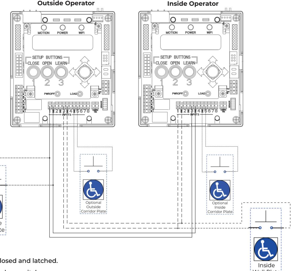
- y The door is normally closed and latched.
-
y Activating the outside door switch:
- ‒ After the Opening Delay 1 has expired, the outside door will open.
- ‒ After the Opening Delay 2 has expired, the inside door will open.
-
y Activating the inside door switch:
- ‒ After the Opening Delay 1 has expired, the inside door will open.
- ‒ After the Opening Delay 2 has expired, the outside door will open.
- y Both doors will close once the set Hold Open time delay has expired.
- y Activating the optional inside door switch located within the corridor will open the inside door only. This door will close after the Hold Open time delay has expired.
- y Activating the optional outside door switch located within the corridor will open the outside door only. This door will close after the Hold Open time delay has expired.
- y Activation can be a wall switch, card reader, key switch, etc (Normally Open momentary dry contacts).

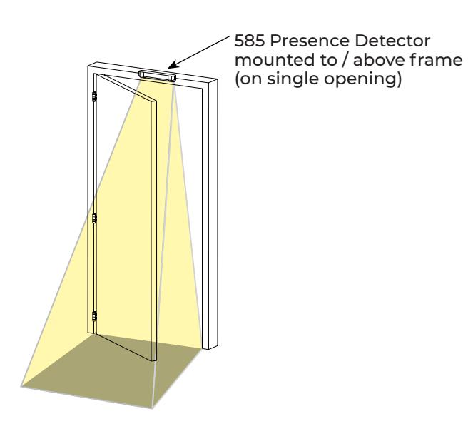
585 Presence Detector on Single Door Opening
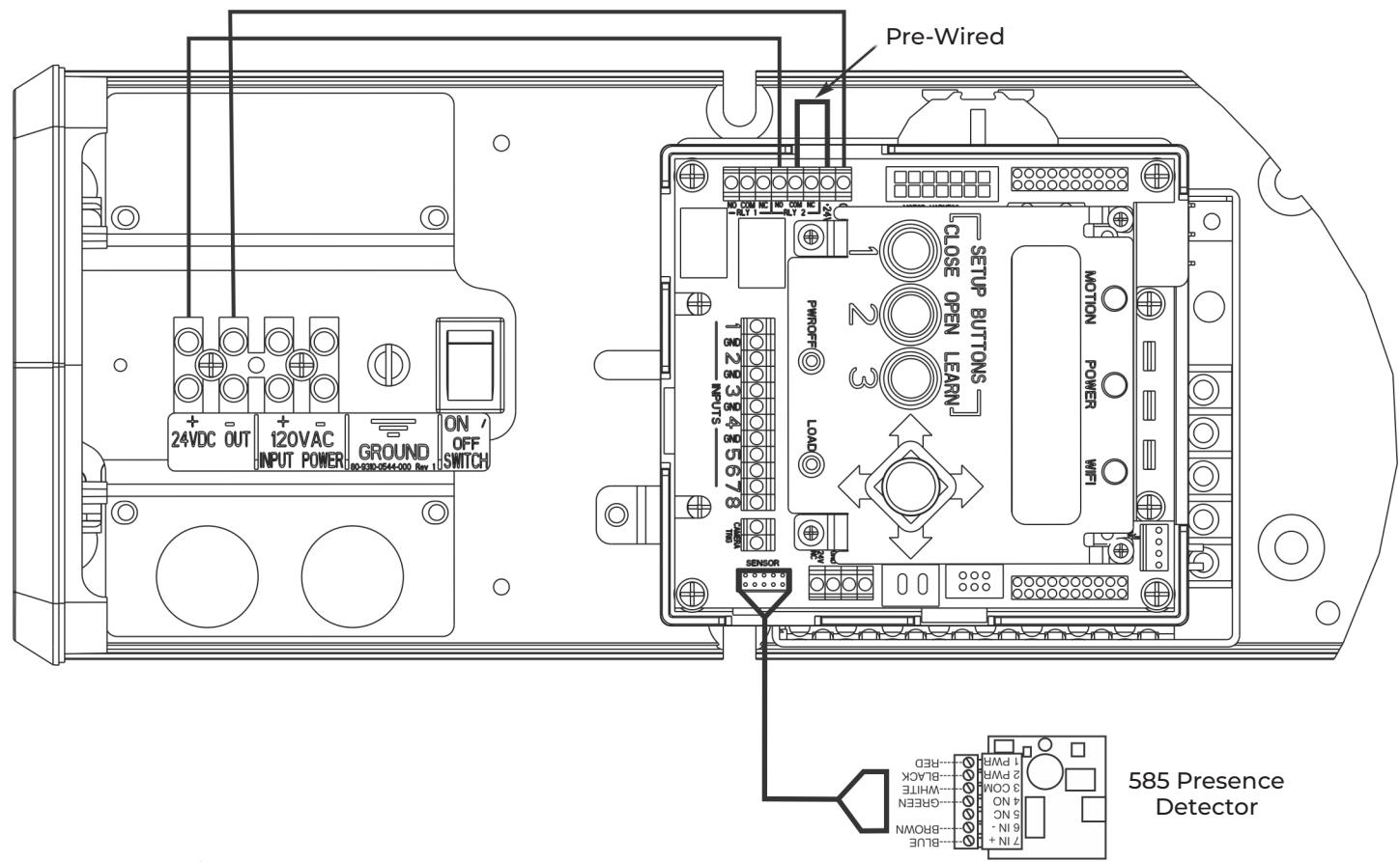
- y The door is normally closed.
- y Activating the switch will open door.
- y The door will close after the hold open time delay has elapsed.
- y If the door is closed and the 585 Presence Detector senses something in the opening, the door will not open when activated.
- y If the door is at an open position and the 585 Presence Detector senses something in the opening, the door will not close after the hold open time delay has elapsed.
- y Once the opening is clear, the door will close after the hold open time delay has elapsed again.

For Low Energy Operators, Presence Detectors and/or sensors CANNOT be used to activate an opening cycle of the door.
To activate the presence detector functionality:
y Use the instructions provided with the 585 sensor to program and make any necessary adjustments to the sensor.

596 Presence Detector on Single Door Opening
(change factory pre-wiring to illustration below - move NO to +24)
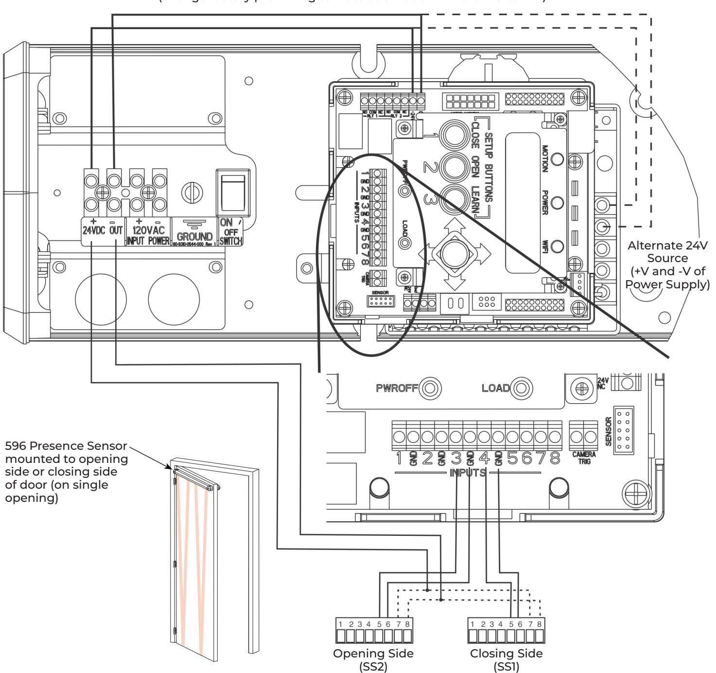
- y The door is normally closed.
- y Activating the switch will open door.
- y The door will close after the hold open time delay has elapsed.
- y If using the door mounted presence sensors: For Closing Cycle sensor (SS1) : Set Input 4 to Obstruction 1 For Opening Cycle sensor (SS2) : Set Input 3 to Obstruction 2

For Low Energy Operators, Presence Detectors and/or sensors CANNOT be used to activate an opening cycle of the door.

Troubleshooting Guide
| Problem | Solution |
|---|---|
| Door closing too fast | Decrease Closing Speed (Onboard: see page 8, Wi-Fi: see page 11) |
| Door closing too slow |
1. Physically adjust Latch and/or Sweep valves on closer counterclockwise OR
2. Increase Closing Speed (Onboard: see page 8, Wi-Fi: see page 11) |
|
Door does not open to
desired location |
1. Repeat Open Position setup process (Onboard: see page 6, Wi-Fi: see page 10), OR
2. Increase Obst Delay (Onboard: see page 8, Wi-Fi: see page 11) |
|
Door does not reach fully
opened position |
1. Repeat Open Position setup process (Onboard: see page 6, Wi-Fi: see page 10), OR
2. Increase Obst Delay (Onboard: see page 8, Wi-Fi: see page 11) |
|
Door opens and closes
repeatedly |
Change Selector Mode switch from H/O to On (see page 4) |
|
Motor is driving in the
wrong direction |
Change Arm Type (Push / Pull). A new Setup is required. (Onboard: see page 5,
Wi-Fi: see page 10) |
|
When door reaches
open position, door drifts toward closed position |
Increase Hold Speed until door stops drifting. (Onboard: see page 8, Wi-Fi: see page 11) |
|
When door reaches
open position, door drifts further open |
Decrease Hold Speed until door stops drifting. (Onboard: see page 8, Wi-Fi: see page 11) |
|
When door reaches open
position, door bounces |
Decrease Slow Speed. (Onboard: see page 8, Wi-Fi: see page 11) |
|
When signal is received,
operator tries to open door before auxiliary components are un latched / retracted |
1. Confirm latch devices are getting proper power,
2. Confirm latch devices are receiving power long enough to fully retract - adjust Latch Retraction on controller as needed, (Onboard: see page 8, Wi-Fi: see page 11) 3. If latch device is not retracting fast enough, increase Start Delay on controller to assure latch device has had sufficient time to fully retract before operator starts opening door. (Onboard: see page 8, Wi-Fi: see page 11) |
|
Error message says
"Short Circuit" |
Turn off power to unit. Check wiring for short / cut. |
|
Error message says "Over
Voltage" |
Check incoming power - line voltage has exceeded 145VAC. |
|
Error message says "Un
der Voltage" |
Check incoming power - line voltage has dropped below 80VAC. |
|
Error message says
"Aux1, Aux 2, or Aux 3 Stuck" |
Disconnect Aux 1, 2, or 3 inputs and confirm error message goes away. If so, make sure input
device is not stuck (sending constant signal). Controller has a 3 minute protection limit. |
|
Error message says
"Comm Error" |
Inverter must be replaced. |
|
Error message says
"Presence Detect" |
Unit has a presence detector attached and device has been activated. |
|
Error message says
"Drive Disabled" |
Selector Mode switch is in the "Off" position. (see page 4) |
33

Technical Product Support: Monroe, NC 28112 USA Phone: 877.974.2255 ext: 2 Techsupport.NortonRixson@assaabloy.com NortonRixson.com