Norton Rixson 5800 Series Low Energy Operator Installation and Operating Instructions_700002
Open the original PDF document
View PDF

ASSA ABLOY
5800 Series Low Energy Operator Installation and Operating Instructions
WARNING: This product can expose you to chemicals including lead, which is known to the State of California to cause cancer or other reproductive harm. For more information go to www.P65warnings.ca.gov/product.
Note
Changes or modifications not expressly approved by the party responsible for compliance could void the user's authority to operate this device. This device complies with part 15 of the FCC Rules. Operation is subject to the condition that this device does not cause harmful interference.
This equipment has been tested and found to comply with the limits for a Class A digital device, pursuant to part 15 of the FCC Rules. These limits are designed to provide reasonable protection against harmful interference when the equipment is operated in a commercial environment. This equipment generates, uses, and can radiate radio frequency energy and, if not installed and used in accordance with the instruction manual, may cause harmful interference to radio communications.
IMPORTANT INSTALLATION INSTRUCTIONS WARNING – To reduce the risk of severe injury or death: READ AND FOLLOW ALL INSTALLATION INSTRUCTIONS
To obtain the latest manual and template revisions or to view installation and programming videos go to www.NortonRixson.com. For technical support call 877-974-2255 ext. 2.


TABLE OF CONTENTS 1. Purpose Discussion Applicability 2. Prerequisites 3. Precautions 4. System Description General Features and Functions 5. Determining The Correct Operator Application Determine the Operator and Door Arm Mounting Installation Type 6. Operator and Door Arm Installation Instructions - Push Side Applications Mounting the Door Arm Pivot Bracket Installing the Door Arm Pivot Installing the Operator Mounting Bracket Installing the Door Operator Installing the Door Arm 7. Operator and Door Arm Installation Instructions - Pull Side Applications Mounting the Door Shoe Installing the Operator Mounting Bracket and Cover Installing the Door Operator Installing the Door Arm 8. Miscellaneous Common Instructions Installing the Push Button Switches Connecting the Battery Pack Installing the Plug-In Transformer Checking Battery Voltage Adjusting Door Spring Tension 9. Programming Instructions Programming the Operator Linking the RF Push Buttons Customizing the Operator Settings (Optional) Setting Optional Functions 10. Closeout Instructions Closeout Procedure 11. Troubleshooting Instructions Attachments: 1: Documents, Definitions, Tools Required, Equipment and Consumables 2: Quick Programming Guide 3: Installation Schematics 3 3 3 4 4 5 5 9 10 10 11 13 16 17 18 19 21 24 25 26 28 29 29 30 31 33 33 34 34 35 35 37 38 38 39 42 43 44
5800 Series Low Energy Operator Installation and Operation Instructions


Discussion
This manual provides system description, installation instructions, operating instructions, troubleshooting recommendations, and a replacement parts listing for the 5800 door operator.
The 5800 is an automatic door opening and closing device that permits automatic operation of single or double right hand or left hand doors measuring 36" to 48" (91 cm to 122 cm) wide and weighing up to 250 lbs (113 kg). The door operator device mounts on a parallel-arm push side configuration or on a standard mount pull side configuration.
The 5800 operator allows the door to open manually or by a remote transmitter device. As the door closes the 5800 operator generates an electrical charge that restores power to the operator battery. If the door is operated via remote transmitter more often than described in the 80/25 rule below, the door-closing cycle will not supply enough power to charge the battery and permit remote operation. In this case an optional plug-in 24VDC Class 2 transformer is required.
The 5800 is an extreme-duty, low-energy door operator designed for institutional, high-traffic manual opening applications that occasionally requires powered operation. A regenerative drive system charges an onboard battery pack, eliminating the need for electrical power. The 5800 should be applied to doors using our 80/25 guideline:
• Apply 5800 to a door that will be cycled manually a minimum of 80 times per day and cycled automatically approximately 25% or less per day.
When applied using this 80/25 guideline the 5800 will self-generate all the power it needs to keep its fieldreplaceable onboard battery pack charged for up to 12 years and in some cases longer.
A fully charged battery can open a door up to 2000 times in a row with little impact on the product's overall usability--even if there are periodic fluctuations from the 80/25 guideline. For example 30% automatic use for one day is not a problem, so long as that level of automatic use is not sustained.
The 5800 can be used in a hardwired application outside of the 80/25 parameters. Simply plug the unit into a common 110-VAC electrical outlet using a plug-in 24VDC Class 2 transformer.
Applicability
This manual is applicable to the 5800 series door operators Left Hand, Right Hand, Push Side Mounted and Pull Side Mounted. The manual also includes instructions for installing the hardwire option (ADA1015P kit).
5800 Series Low Energy Operator Installation and Operation Instructions

2 Prerequisites
- 1. If the door is an aluminum storefront door, make sure that you do not drill into the tie rod or the top rail web. Also, do not drill into the junction of the style and rail.
- 2. When using a plug-in 24VDC Class 2 transformer, a 110-VAC grounded power outlet is available in the vicinity of the door.
- 3. A protective barrier (caution/warning tape) has been set up to prevent unauthorized access to work area.
- 4. If applicable, the existing door closer has been removed.
- 5. The operator must only be installed on doors and frames in good working order, without sticking or binding during normal operation.
- 6. The door has been secured to prevent unexpected opening or closing during installation.
-
7. Attachment 1 has been reviewed for the following:
- Definitions of the terms used in this procedure
- A listing of the tools, equipment, materials, and consumables used in this procedure.
3 Precautions
- 1. Improper installation or adjustment may result in personal injury or property damage. The operator must be completely installed and programmed or the door must be disabled prior to leaving the site. An incomplete installation or unprogrammed operator can cause a safety hazard. Follow all instructions carefully. For questions call Norton Rixson Technical Support at the number listed on the front of this document.
- 2. For light duty or hollow core doors with insufficient top rail blocking, the included through bolts or sex nut and bolts must be to securely attached to the operator mounting bracket.
- 3. This product is intended for interior use only.
- 4. Do not connect the door operator to source of power until instructed to do so. Applicable only if unit will be wired to external power.
- 5. The operator battery should be switched "OFF" until the operator and door arm installation are complete.
- 6. An operating door creates pinch hazards. Be careful making operating adjustments while the door is moving.
- 7. The installation must comply with all local, state, and national electrical codes. Transformer wiring must be secured to prevent it from becoming entrapped in the moving parts of the operator or door.


General
The 5800 operator is shipped in the following pieces (see Figure 1):
- Operator assembled with black cover installed
- Optional silver cover (when specified)
- Door arm assembly
- Operator mounting bracket
- Shaft extension (pull side applications only)
- Door arm mounting shoe (pull side applications only)
- Operator mounting bracket cover
- Operator mounting posts
- Door arm pivot assembly (push side applications only)
- Battery assembly installed but disconnected from the operator
- Two wireless push buttons
- Operator mounting templates (right hand and left hand)
- Hardware pack including fasteners for aluminum and hollow metal, wood, and all installations
Door decals including the following:
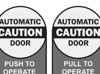
- Two yellow and blue "CAUTION AUTOMATIC DOOR, ACTIVATE SWITCH TO OPERATE" decals, "PUSH TO OPERATE" and "PULL TO OPERATE" decals for use with the optional Push & Go feature.
- One yellow "DAILY SAFETY CHECK" decal

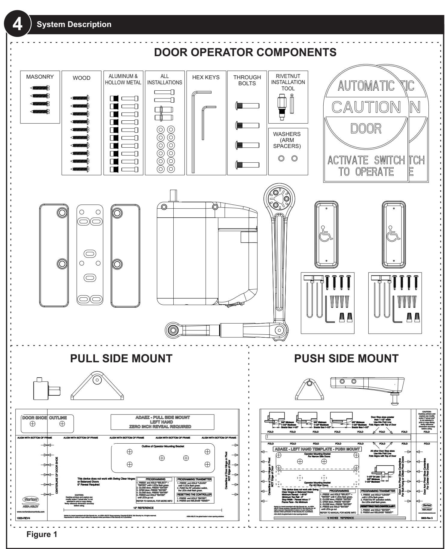

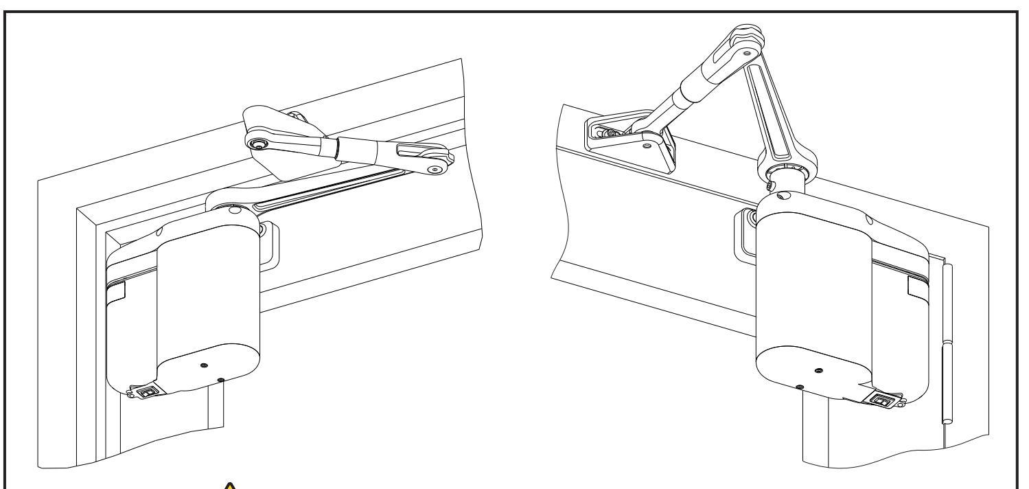
Figure 2 illustrates an assembled 5800 operator installed on a left hand door. The paragraphs that follow describe its components:


Door Operator Assembly:
Includes the following major assemblies:
- Door Operator: Contains the mechanical components required to move the door. The operator assembly mounts on the hinge or pivot edge of the door and top rail and includes the motor/gearbox, door arm, mounting brackets, regenerative power source, battery pack, and cover.
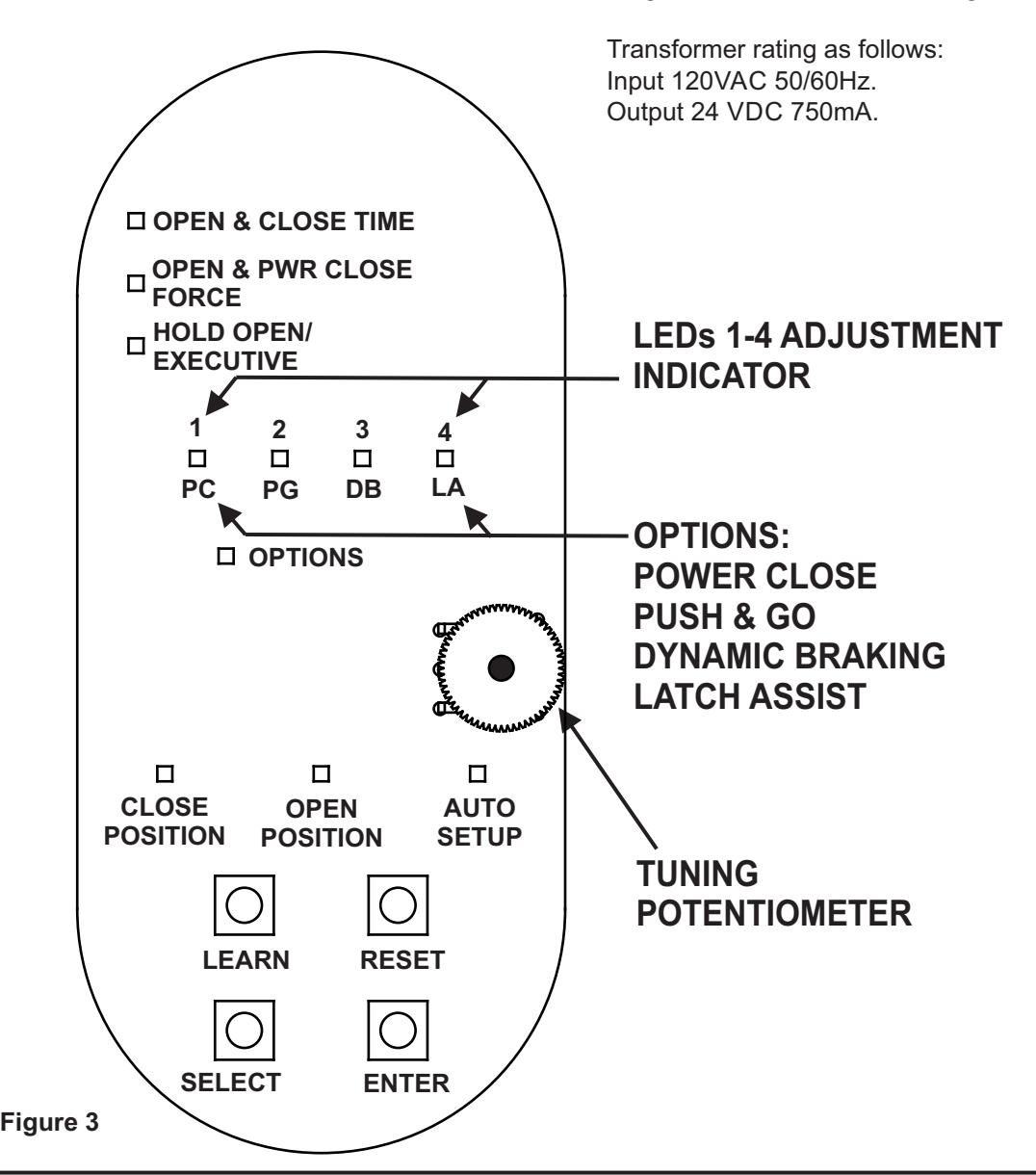
- Door Controller: Contains the hardware and software necessary to control the motion of the door. Figure 3 illustrates the door controller circuit board controls and indicators.
Transmitter:
An external device that emits an RF signal or an electrical signal to operate the door. When pushed once, the door opens. The transmitter has a range of 85' (26 m) from either side of the door.
One 3-volt 280mAH lithium battery (Part No.CR2032) provides transmitter power. The battery provides approximately 250,000 activations.
Transformer:
A 24VDC Class 2 transformer kit converts the incoming 110 VAC power to the voltage required by the controller. Plugs into a standard 110-VAC grounded power outlet.

Features and Functions
Opening Time:
Following an activation signal, door moves from fully closed to open check or 80°, whichever occurs first. Opening time shall be in accordance with Table 1.
Hold-Open Time:
Hold open time shall be adjusted to no less than 5 seconds.
Closing Time:
Following hold-open time, door moves from fully open to close check or 10°, whichever occurs first, according to Table 1.
Close Check:
Close check shall occur in last 10° of closing and shall not be less than 1.5 seconds.
Closing Force:
Door shall not close with a force greater than 15 lbs (6.8 kg) when measured at latch side of closing stile. For the 5800 series, closing force is adjustable to 8 lbs (3.6 kg).
Open and Power Close Force:
The operator shall be adjusted so that a stopped door will apply a force in the opening direction of 15 lbs or less. If the optional Power Close feature is enabled the door shall be adjusted so that a stopped door will apply a force of less than 15 lbs in the closing direction.
Transmitter Range:
Transmitter has a range of 85' (26 m) from either side of door.
Operation Upon Loss of Power:
Standard installations require no external power and operation will not be affected during a power loss. Typically a maximum of 2,500 cycles can be obtained from a fully charged battery pack. Installations with a power transformer will continue to function normally.
Operation Upon Obstruction:
If door meets an obstruction while opening, door will remain under power for one second and then close under spring force. If door meets an obstruction while closing, door will maintain a closing force of 8 lbs (3.6 kg) or less.
Transmitter Learn Mode:
Transmitter Learn Mode programs transmitter to operator. The system can learn up to twelve separate transmitters. The system also has the ability to remove all transmitters programmed into memory.
Auto-Setup Mode:
Auto-Setup Mode allows door to "learn" its fully open and fully closed positions and adjusts the open time, close time, open force, and hold open times to ensure settings meet ANSI A156.19 Low Energy Door Operator Code.
Option Features:
- Power Close: Door operator will apply a small amount of power if door did not close in expected close time to assist in closing door. Once door is fully closed power close will turn off.
- Push & Go: Operator will power open door when the door is manually moved in the open direction.
- Dynamic Braking: Operator will brake door if excessive door speed occurs resulting, for example, from a wind load or an abusive open condition.
- Latch Assist: Operator will apply a force in the close direction for 1/2 second when the operator receives an activate signal to assist an electric strike in unlocking. When the door closes the operator will apply a force in the close direction to assist in latching the door.
Hold Open/Executive:
Operator provides an adjustable hold open time. Controls on circuit board allow adjustment of doorclosing time delay from 1 second to 30 seconds. ANSI 156.19 requires the door hold open for a minimum of 5 seconds which is the default hold open setting. When Executive mode is activated the door will open when it receives an activate signal and remain open until it receives a second activate signal.
NOTE: Power Close, Push & Go, Latch Assist, and Executive Mode must only be enabled when unit is powered using optional 24VDC Class 2 plug in transformer.

5 Determining the Correct Operator Application
Determine the Operator and Door Arm Mounting Installation Type
CAUTION
The operator must only be installed on doors and frames that are in good working order. The door must not stick or bind during normal operation.
If applicable, the existing door closer must be removed before installing the 5800 operator.
The operator must be completely installed and programmed or the door must be disabled prior to leaving the site. An incomplete installation or unprogrammed operator can cause a safety hazard.
NOTE: A push mount operator always mounts on the inside (push side) of the door at the hinge or pivot edge of the top rail. A pull mount operator always mounts on the outside (pull-to-open) of the door.
The 5800 will not work on balanced doors or doors with swing clear hinges.
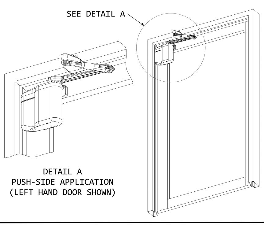
- 1. Refer to Figure 4, and DETERMINE desired door handing.
-
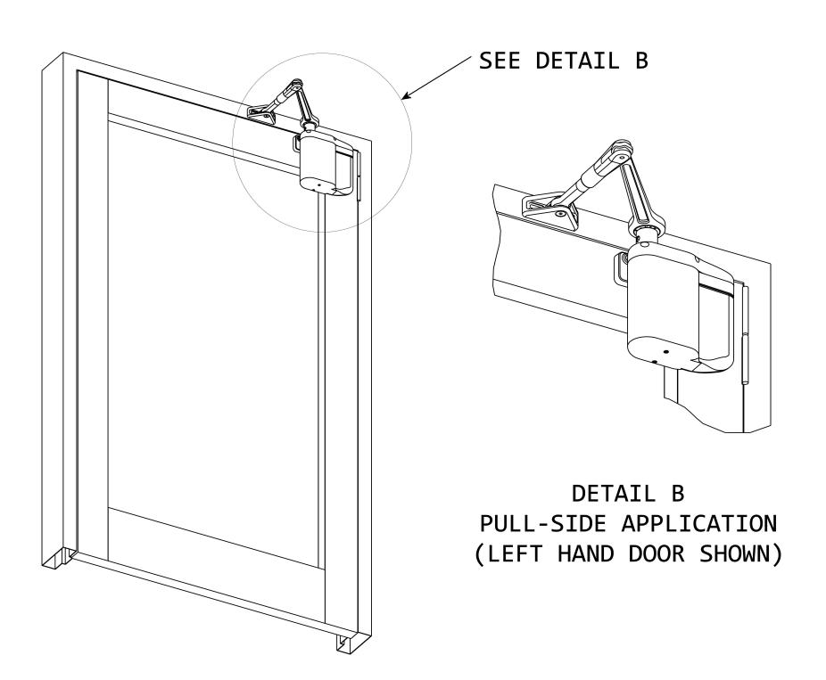
2. Refer to Figure 5, and DETERMINE if the door is a push side application or a pull side application.
- If the door is a push side application, GO TO Section 6.
- If the door is a pull side application, GO TO Section 7.
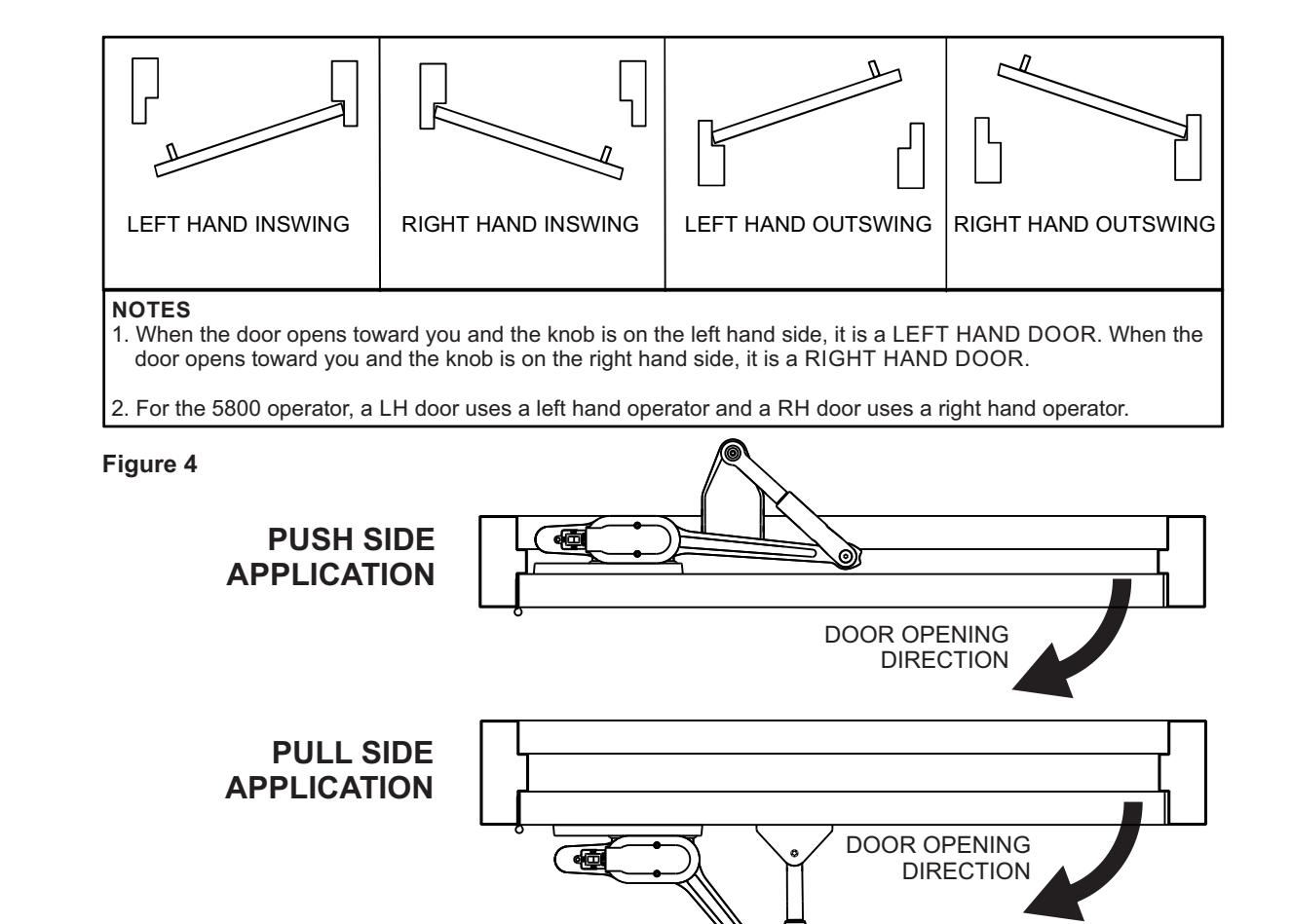
Figure 5
NOTE: Operator always mounts on inside of door at hinge or pivot edge of top rail. Template provides for Right Hand door mounting on one side and Left Hand door mounting on opposite side.
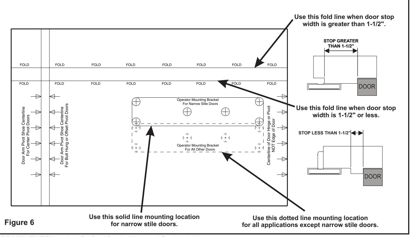
The template has a solid-line outline and a dotted-line outline. The solid-line outline is for narrow rail door. The dotted line outline is for medium or wide rail doors.
Each template provides two additional hole slots. Use a minimum of 4 mounting hole locations that will not interfere with a top rail web, rail-to-stile tie rod(s), or rail-to-stile junction.
- 1. SELECT right hand or left hand operator mounting template as applicable.
- 2. EXAMINE inside door top rail and DETERMINE top rail width (narrow, medium, or wide).
- 3. DETERMINE type of mounting hinge (butt or continuous, center pivot, or offset).
CAUTION
On an aluminum storefront door, the operator mounting holes must not be drilled into the top rail web, rail-tostile tie rod(s), or the rail-to-stile junction.
-
4. If door is an aluminum storefront door, EXAMINE top rail, and, when drilling mounting holes, ENSURE the following:
- Do not drill into the top rail web
- Do not drill into the rail-to-stile tie rod(s)
- Do not drill into the rail-to-stile junction
-
5 Refer to Figures 6 and 9, and DETERMINE which operator mounting template fold line to use as follows:
-
a. MEASURE the stop thickness.
- If the stop is greater than 1-1/2" (38 mm), USE the upper template fold line.
- If the stop is 1-1/2" (38 mm), or less, USE the lower template fold line.
- b. If the door is a narrow-stile door, USE the solid line mounting location.
- c. If the door is an application other than a narrowstile door, USE the dotted line mounting location.
-
a. MEASURE the stop thickness.


CAUTION
To ensure proper installation, the operator must be fastened with at least four fasteners. For heavier doors more fasteners are recommended.
For light duty or hollow-core doors with insufficient top rail blocking, the included through bolts or sex nut and bolts must be used to securely attached the operator mounting bracket.
- 7. Using a center punch, MARK the mounting hole locations.
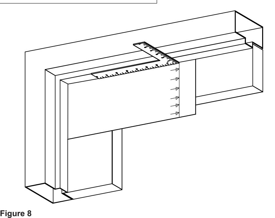
- 8. Refer to Figure 8, and, using a square, MARK the centerline of the arm pivot onto the underside and face of the frame header and door stop. (This line is shown on the template.)
Mounting the Door Arm Pivot Bracket
NOTE: The face of the triangular vertical support must be flush against the face of the frame header. On some door installations, the door stop prevents the bracket from setting flush. If this is the case, the arm pivot bracket can be adjusted by removing the bracket vertical support and reversing it.
In a flush mount installation, the ceiling covers the frame face. In this case, the vertical support of the bracket is not used. The bracket should then be mounted to the underside of the frame header.
- 1. Refer to Figure 9, and DETERMINE if the pivot bracket must mount to the face of the stop or the face of the rabbet
-
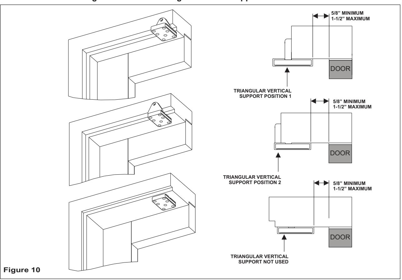
2. Refer to Figure 10 and DETERMINE the mounting location of the triangular vertical support bracket.
- The edge of the bracket must be between 5/8" (16 mm) and 1-1/2" (38 mm) from the face of door.
- If the door is a typical installation, the triangular vertical support will set flush against the face of the frame header.
- If the door is a large reveal installation, the arm pivot bracket will mount to the underside of the frame header.
Figure 9

STOP LESS THAN 1-1/2" 6 Operator And Door Arm Installation Instructions - Push Side Applications Determining the Door Arm Pivot Bracket Mounting Location. STOP GREATER THAN 1-1/2" WHEN STOP IS GREATER THAN 1-1/2" WIDE - MOUNT PIVOT BRACKET TO THE FACE OF THE STOP DOOR
WHEN STOP IS LESS THAN 1-1/2" WIDE - MOUNT PIVOT BRACKET TO THE FACE OF THE RABBET
DOOR
Determine the mounting location of the triangular vertical support bracket

CAUTION
To ensure proper installation, the door arm pivot bracket must be fastened to the underside of the header frame and to the face of the header frame with at least three fasteners.
NOTE: When attempting to install the rivnuts to the underside of the door frame it may be necessary to remove the door stop.
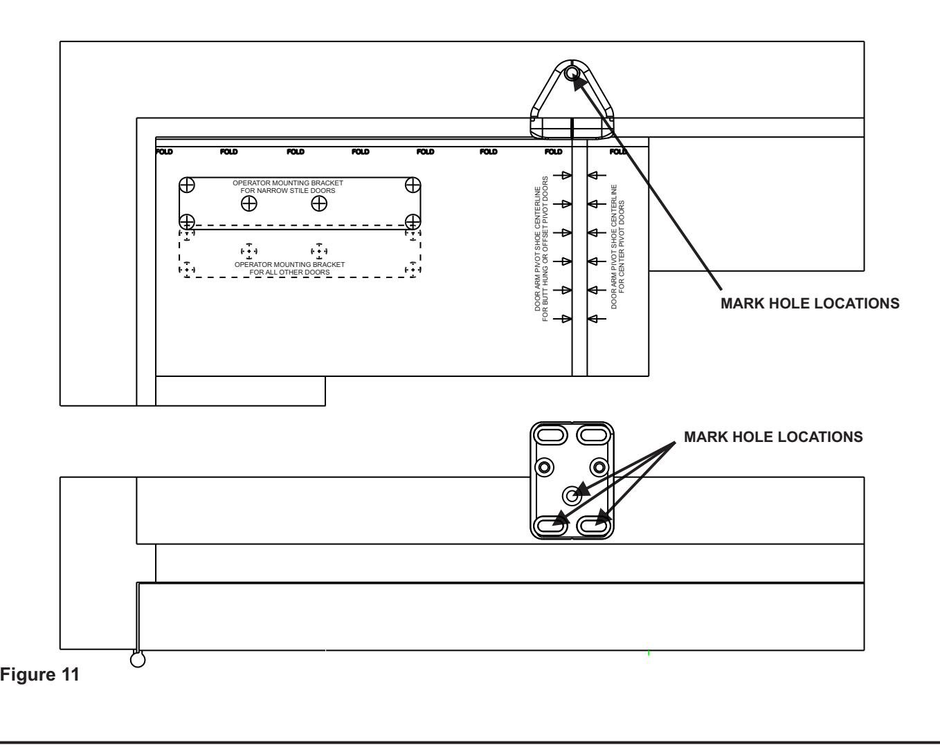
- 2. Refer to Figure 11 and, using a center punch, MARK the door arm pivot bracket hole locations.
- 3. If the door frame is aluminum and rivnuts must be installed, PERFORM the following:
- a. Using a 25/64″ drill, DRILL the door arm pivot bracket holes.
- b. Using the provided rivnut installation tool, INSTALL the ¼-20 steel rivnuts.
- c. INSTALL and TIGHTEN the three (minimum) ¾" socket head capscrews securing the door arm pivot bracket to the underside and face of the frame header.
-
4. If the door frame is wood, PERFORM the following:
- a. Using a 5/32" drill, DRILL the door arm pivot bracket pilot holes.
- b. INSTALL and TIGHTEN the three #14 x 1-¼" wood screws (minimum) securing the door arm pivot bracket to the underside and face of the frame header.

Installing the Door Arm Pivot
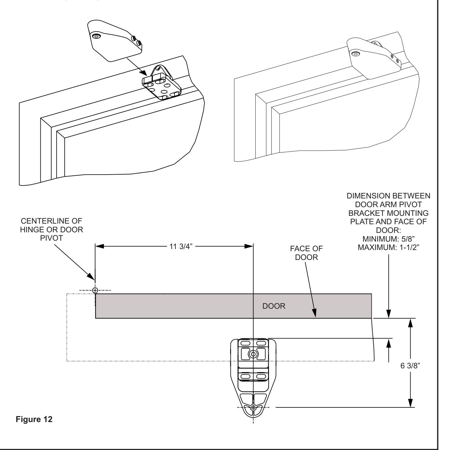
- 1. Refer to Figure 12, and SLIDE the door arm pivot over the door arm pivot bracket.
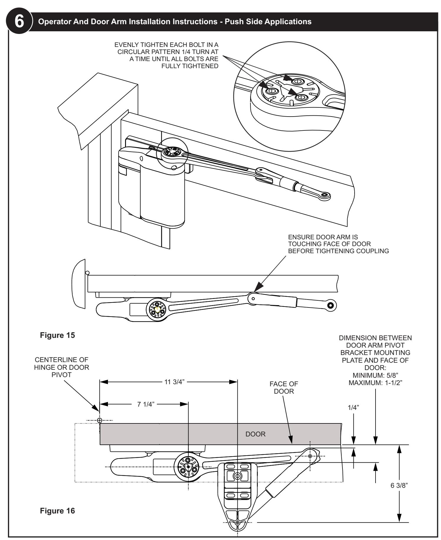
- 2. ENSURE that the dimension from the face of the door to the centerline of the door arm mounting hole is 6-3/8" (162 mm).
- 3. TIGHTEN the four set screws securing the door arm pivot to the door arm pivot bracket.

Installing the Operator Mounting Bracket
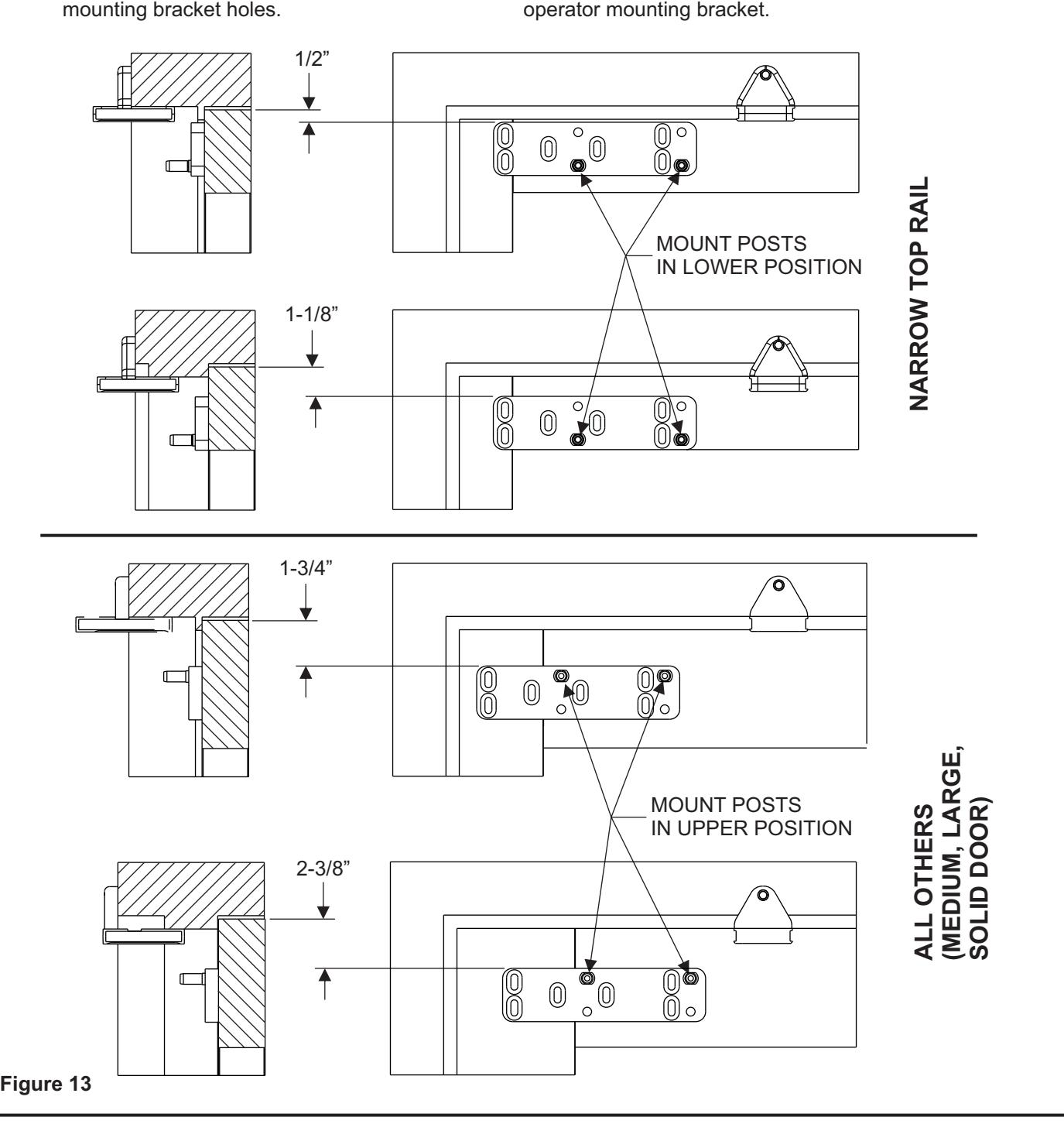
- 1. Refer to Figure 13, and DETERMINE the proper operator mounting bracket location.
-
2. If the door is aluminum rivnuts must be installed, PERFORM the following:
- Using a 25/64″ drill, DRILL the operator
- 3. Using the provided rivnut installation tool, INSTALL the ¼-20 steel rivnuts.
NOTE: For light duty or hollow-core doors with insufficient top rail blocking, through bolts or sex nut and bolts are required to securely attached the
5800 Series Low Energy Operator Installation and Operation Instructions

6 Operator And Door Arm Installation Instructions - Push Side Applications
-
4. If the door is wood or hollow metal, PERFORM the following:
- Using a 3/8" drill, DRILL the operator mounting bracket holes.
- 5. INSTALL and TIGHTEN the supplied throughbolts, the four ¼-20 socket head capscrews (with supplied washers) securing the operator mounting bracket. INSTALL a washer onto each of the four (minimum) ¾" socket head operator mounting bracket capscrews.
- 6. INSTALL, but DO NOT TIGHTEN the socket head capscrews securing the operator mounting bracket to the door.
-
7. ADJUST the operator mounting bracket as follows:
- If the upper fold on the operator mounting template was used (large stop mounting), ADJUST the bracket so that there is 2-3/8" (60 mm) space between the top of the bracket and the top of the door.
- If the lower fold on the operator mounting template was used (standard mounting), ADJUST the bracket so that there is 1¾" (45mm) space between the top of the bracket and the top of the door.
- If the narrow stile door mounting location was used (solid line on operator mounting template), ADJUST the bracket so that there is 1/2" (13 mm) space between the top of the bracket and the top of the door.
8. TIGHTEN the socket head capscrews securing the operator mounting bracket to the door.
NOTE: The operator mounting bracket includes four threaded holes that accept the operator mounting pins. The lower set of two threaded holes is used when the operator is installed on a narrow-rail door. The upper set of two threaded holes is used when the operator is installed on a medium- or wide-rail door.
-
9. Refer to Figure 13 and PERFORM one of the following as applicable:
- If the operator is being mounted to a narrow rail door, TIGHTEN the operator mounting pins into the lower threaded holes in the mounting bracket using a 7/16" box wrench or large adjustable wrench.
- If the operator is being mounted to a wide or medium rail door, TIGHTEN the operator mounting pins into the upper threaded holes in the mounting bracket using a 7/16" box wrench or large adjustable wrench.
Installing the Door Operator
- 1. Refer to Figure 14, and INSTALL the operator mounting bracket cover over the operator mounting bracket.
- 2. REMOVE the two capscrews securing the operator bottom cover to the operator.
- 3. REMOVE the bottom cover from the operator.
- 4. SLIDE the battery pack from the operator and REMOVE the battery pack.
- 5. REMOVE the dress cover from the operator.
WARNING
To avoid inadvertent activation of the operator during connection of the door arm, the battery pack should not be installed until after the door arm is connected.
- 6. With the battery pack facing the jamb, POSITION the operator onto the operator mounting pins. ENSURE the operator does not slide off the mounting pins.
- 7. INSTALL and TIGHTEN the two ¼-20 X 1½" socket head capscrews securing the operator to the operator mounting pins.


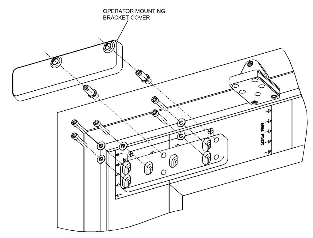
Figure 14
Installing the Door Arm
1. Refer to Figure 15, and, with the door arm coupling screws facing up and the door arm against the door rail, POSITION the larger end of the door arm onto the operator output shaft.
CAUTION
The door arm coupling is a two-piece tapered coupling. In order to draw the coupling halves together evenly the three door arm coupling screws must be tightened evenly (one quarter turn at a time) until fully tight.
- 2. With the door arm touching the face of the door, TIGHTEN the door arm coupling screws evenly (one quarter turn at a time) until fully tight.
- 3. HOLD the elbow of the door arm against the face of the door, and THREAD the adjustable door arm end link into the door arm as necessary to align the end link mounting hole with the door arm pivot mounting hole.


-
4. If the door arm end link does not align with the door arm pivot mounting hole and there is no available travel on the threaded end link, PERFORM the following:
- LOOSEN the socket head capscrews securing the door arm pivot to the door arm pivot bracket.
- SLIDE the door arm pivot as necessary to align the door arm end link with the door arm pivot mounting hole.
- TIGHTEN the socket head capscrews securing the door arm pivot to the door arm pivot bracket.
CAUTION
In order to apply a preload to the door, the door arm must be threaded into the door arm three revolutions. Excessive pre-load will reduce the closing force of the operator and may cause the door to stick in the open position or the door arm to reverse.
5. Apply preload to ensure proper closing. THREAD the adjustable door arm end link into the door arm three revolutions so the hole in the arm is approximately 1/2 diameter off from the hole in the door arm pivot as shown in Figure 17.
- NOTE: An extra washer is supplied if needed to prevent rubbing between the top of the door arm and end link.
- 6. INSTALL the washer provided onto the top of the door arm end link, and TIGHTEN the 5/16 -18 X 7/8" button-head capscrew securing the door arm end link to the door arm pivot bracket.
- 7. CYCLE the door several times, and ENSURE that the door opens and closes smoothly.
- 8. Refer to Figure 16 and verify all mounting dimensions.
- 9. SLIDE the dress cover onto the operator.
- 10. CONNECT the battery pack connector plug to the operator.
- 11. SLIDE the battery pack onto the operator, and ENSURE that the battery pack wires will not interfere with the operator cover.
- 12. SWITCH the battery pack to the "ON" position.
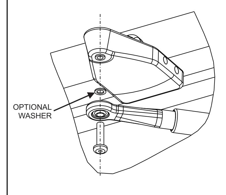
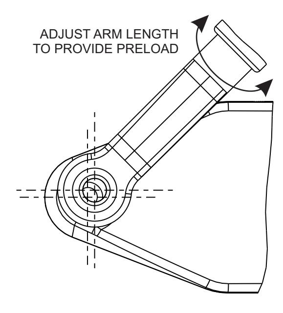
Figure 17


NOTE: A pull mount operator always mounts on the outside (pull-to-open) of the door at the hinge or pivot edge of the top rail.
The template provides for Right Hand door mounting on one side and Left Hand door mounting on the opposite side. The template provides 6 mounting hole locations for the operator bracket. A minimum of 4 locations must be used. Select the 4 mounting holes that will not interfere with a top rail web, rail-to-stile tie rod(s), or the rail-to-stile junction.
1. SELECT the right hand or left hand side of the operator mounting template as applicable. Refer to Figure 18.
2. DETERMINE the type of mounting hinge (butt, continuous, or offset).
CAUTION
On an aluminum storefront door, the operator mounting holes must not be drilled into the top rail web, rail-to-stile tie rod(s), or the rail-to-stile junction.
-
3. If door is an aluminum storefront door, EXAMINE top rail, and, when drilling mounting holes, ENSURE the following:
- Do not drill into the top rail web
- Do not drill into the rail-to-stile tie rod(s)
- Do not drill into the rail-to-stile junction
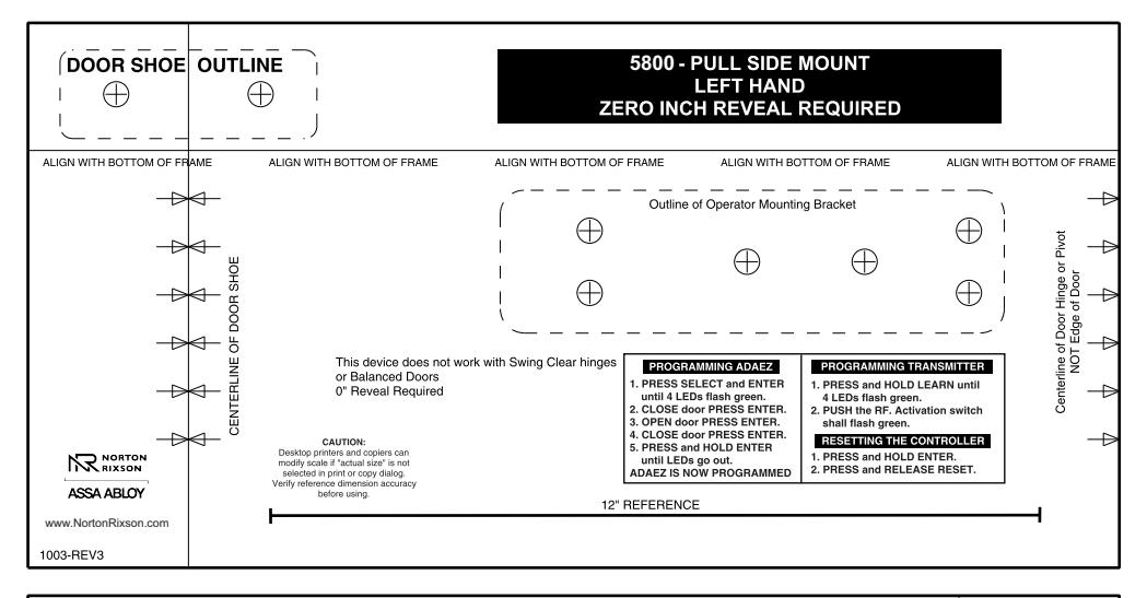
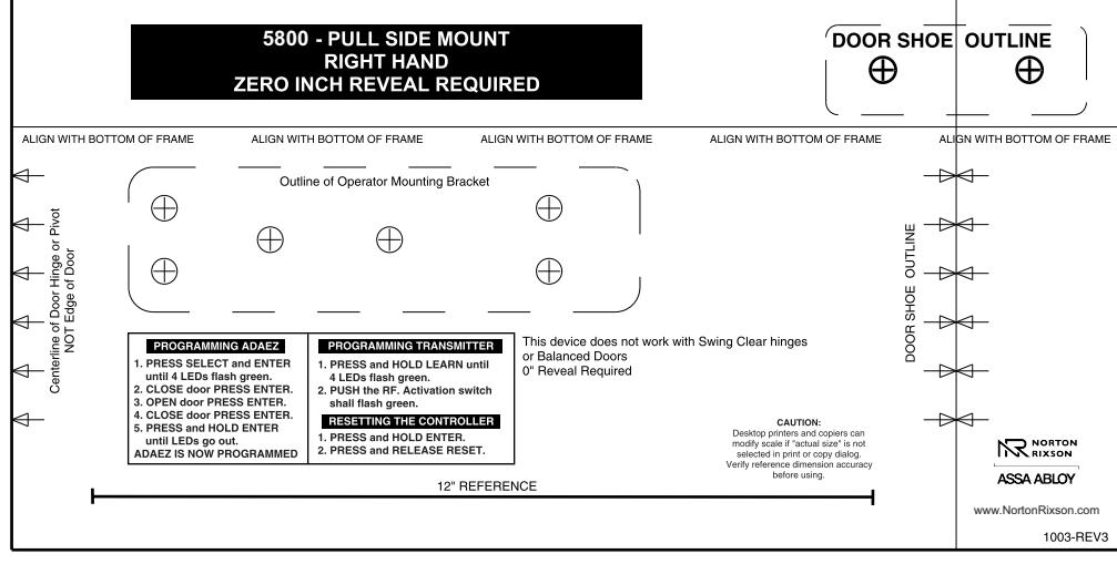
Figure 18

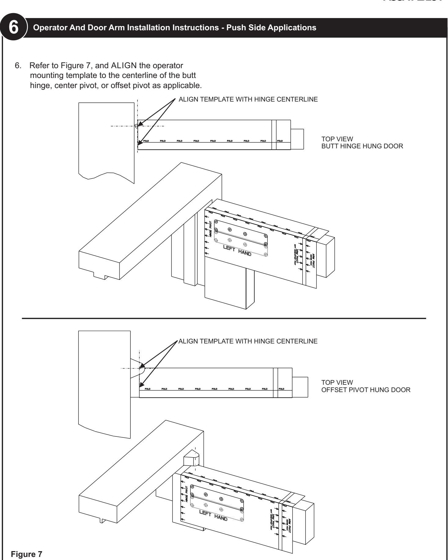
- 4. Refer to Figure 19, and ALIGN the operator mounting template to the centerline of the butt hinge, center pivot, or offset pivot as applicable.
- 5. Using a center punch, MARK the operator mounting bracket hole locations.
- 6. Using a center punch, MARK the door shoe mounting hole locations.
CAUTION
To ensure proper installation, the operator must be fastened with at least four fasteners. For heavier doors more fasteners are recommended.
For light duty or hollow-core doors with insufficient top rail blocking, through bolts or sex nut and bolts are required to securely attached the operator mounting bracket.
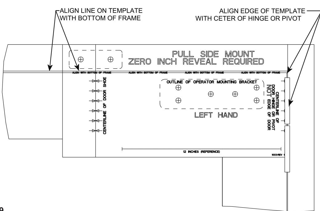
Figure 19


Mounting the Door Shoe
-
1. If the door frame is steel or aluminum and rivnuts must be installed, refer to Figure 20 and PERFORM the following:
- a. Using a 25/64" drill, DRILL the door arm pivot bracket holes.
- b. Using a rivnut tool, INSTALL the ¼-20 steel rivnuts.
- c. INSTALL and TIGHTEN the two (minimum) ¾" socket head capscrews (with black oxide washers) securing the door arm pivot bracket to the underside and face of the frame header.
-
2. If the door frame is wood, refer to Figure 18 and PERFORM the following:
- a. Using a 5/32" drill, DRILL the door arm pivot bracket pilot holes.
- b. INSTALL and TIGHTEN the three #14 x 1-¼" wood screws (minimum) securing the door arm pivot bracket to the underside and face of the frame header.
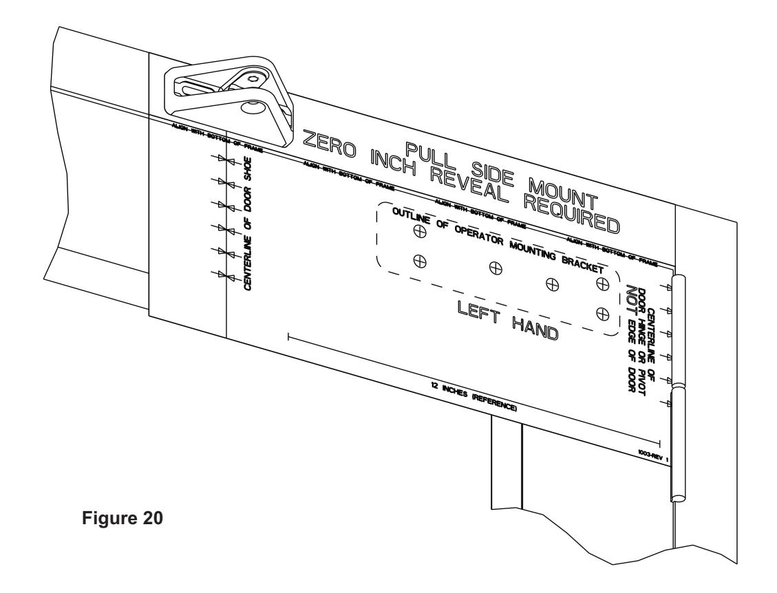


Installing the Operator Mounting Bracket and Cover
CAUTION
For light duty or hollow-core doors with insufficient top rail blocking, the provided through-bolts or sex nuts and bolts must be used to securely attach the operator mounting bracket.
-
1. If the door is aluminum and rivnuts must be installed, refer to Figure 21 and PERFORM the following:
- a. Using a 25/64" drill, DRILL the mounting bracket holes.
- b. Using the provided rivnut tool, INSTALL the ¼-20 steel rivnuts.
- c. INSTALL and TIGHTEN the four(minimum) ¼-20 socket head capscrews (with supplied washers) securing the operator mounting bracket.
- 2. If the door is wood, refer to Figure 21 and PERFORM the following:
- a. Using a 3/8" drill, DRILL the mounting bracket pilot holes.
- b. INSTALL and TIGHTEN the supplied throughbolts, the four ¼-20 socket head capscrews (with supplied washers) securing the operator mounting bracket.
- 3. ADJUST the bracket so that there is a 5/8" (16mm) space between the top of the bracket and the top of the door.
- 4. TIGHTEN the socket head capscrews securing the mounting bracket to the door.
- 5. Using a 7/16" box wrench or large adjustable wrench, TIGHTEN the operator mounting pins into the upper threaded holes in the mounting bracket.
- 6. INSTALL the operator mounting bracket cover over the operator mounting bracket.
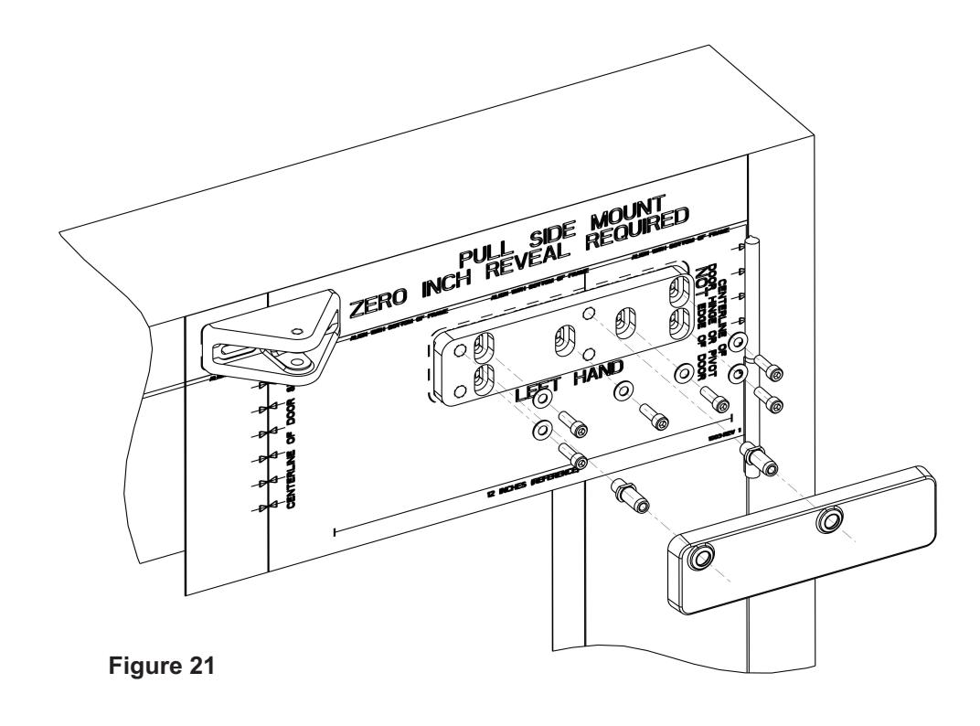


Installing the Door Operator
- 1. REMOVE the two capscrews securing the operator bottom cover to the operator.
- 2. REMOVE the bottom cover from the operator.
- 3. SLIDE the battery pack from the operator and REMOVE the battery pack.
- 4. REMOVE the dress cover from the operator.
- 5. INSTALL and TIGHTEN the two ¼-20 X 1½" socket head capscrews securing the operator to the operator mounting pins.
WARNING
To avoid inadvertent activation of the operator during connection of the door arm, the battery pack should not be installed until after the door arm is connected. Refer to Figure 22, and, with the battery pack facing the jamb, POSITION the operator onto the operator mounting pins. ENSURE operator does not slide off the mounting pins.
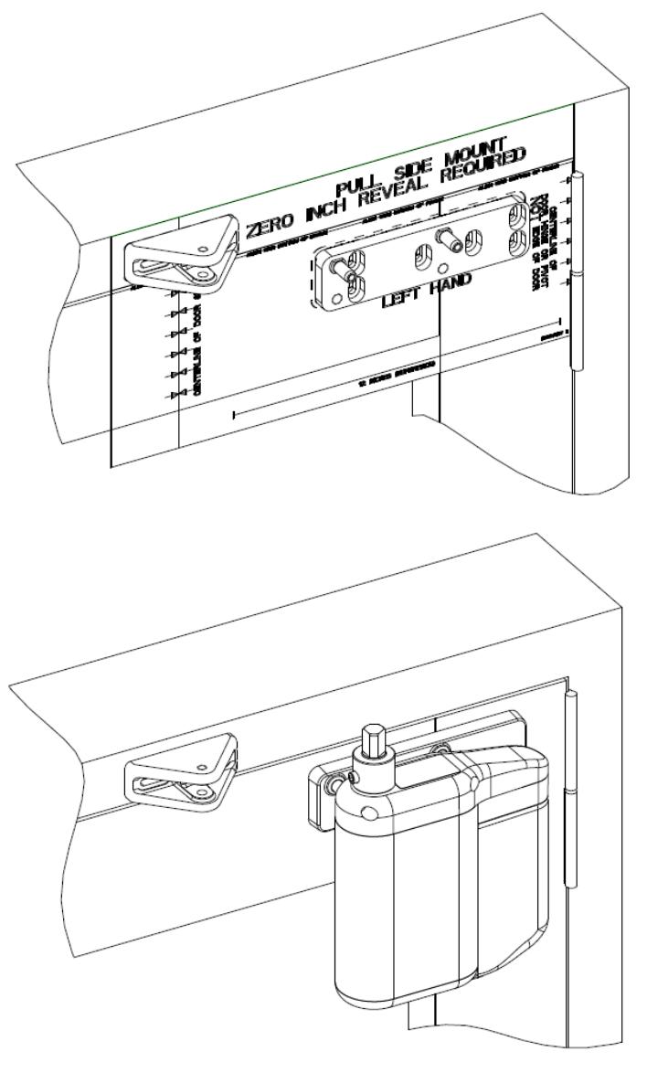
Figure 22

Installing the Door Arm
- 1. Refer to Figure 23, and INSTALL shaft extension onto operator shaft.
- 2. TIGHTEN set screw securing shaft extension to operator shaft.
- 3. Refer to Figure 24, and ADJUST door arm length to 8 1/16" (205 mm).
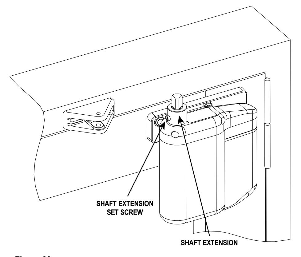
Figure 23
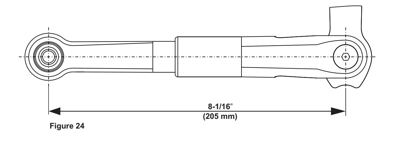
4. Refer to Figure 25, and , with the door arm coupling screws facing up, POSITION the larger end of the door arm onto the operator output shaft. Align the hole in the end of the door arm approximately 1/2 hole away from the hole in the mounting bracket.
CAUTION
The door arm coupling is a two-piece tapered coupling. In order to draw the coupling halves together evenly the three door arm coupling screws must be tightened evenly (one quarter turn at a time) until fully tight.
5. Refer to Figure 26, and, while maintaining the door arm position, TIGHTEN the door arm coupling screws evenly (one quarter turn at a time) until fully tight.
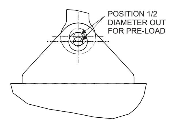
Figure 25
Figure 26 EVENLY TIGHTEN EACH BOLT IN A CIRCULAR PATTERN 1/4 TURN AT A TIME UNTIL ALL BOLTS ARE FULLY TIGHTENED
- 6. INSTALL the 5/16 18 flat head screw into the door shoe mounting bracket to secure the door arm.
- 7. CYCLE the door several times, and ENSURE that the door opens and closes smoothly.
- 8. SLIDE the dress cover onto the operator.
- 9. CONNECT the battery pack connector plug to the operator.
- 10. SLIDE the battery pack onto the operator, and ENSURE that the battery pack wires will not interfere with the operator cover.
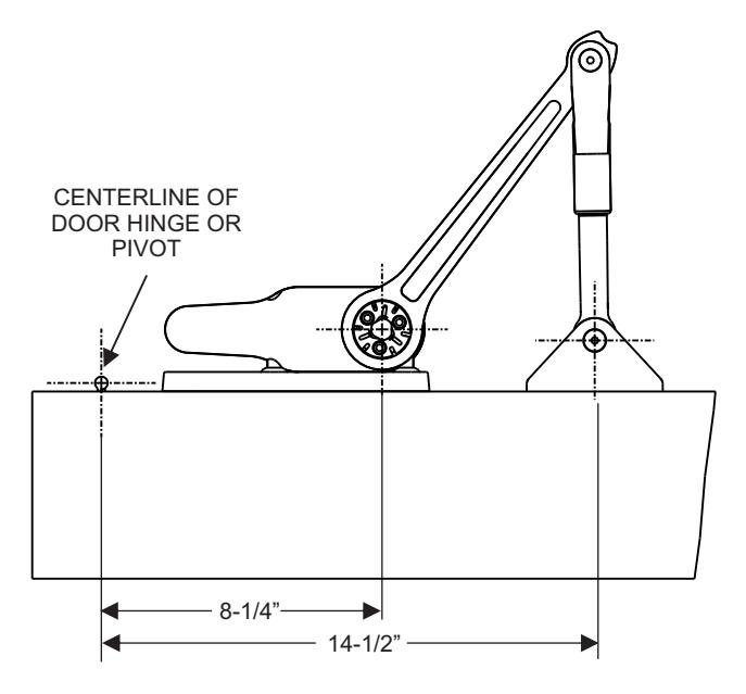

Installing the Push Button Switches
NOTE: The instructions for installing the push button switches, installing the plug-in transformer, adjusting door spring tension, and replacing the battery pack fuse are common regardless of whether the door is a push or pull application.
-
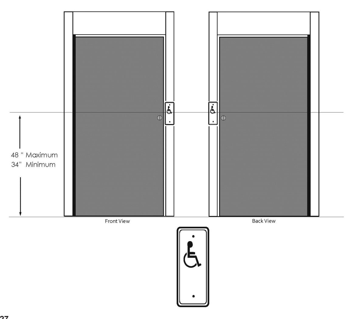
1. Refer to Figure 27, and INSTALL the push button switches. ENSURE the following:
- Switches are located 1' to 12' (30 cm to 3.7m) from the door.
- Switches remain accessible from the swing side when the door is opened.
- Switches are not located in a position where the user would be in the path of the moving door.
- Switches are mounted so that the user is in full sight of the door when activating the switch.
- Switches are mounted at a minimum height of 34″ (86 cm) and a maximum height of 48″ (122 cm).
- 2. Unless otherwise approved by the Authority Having Jurisdiction (AHJ), CONSULT ANSI A117.1, "Standard on Accessible and Usable Buildings and Facilities," and other applicable building codes for additional information regarding accessibility requirements for the door and the area around the door.

Connecting the Battery Pack
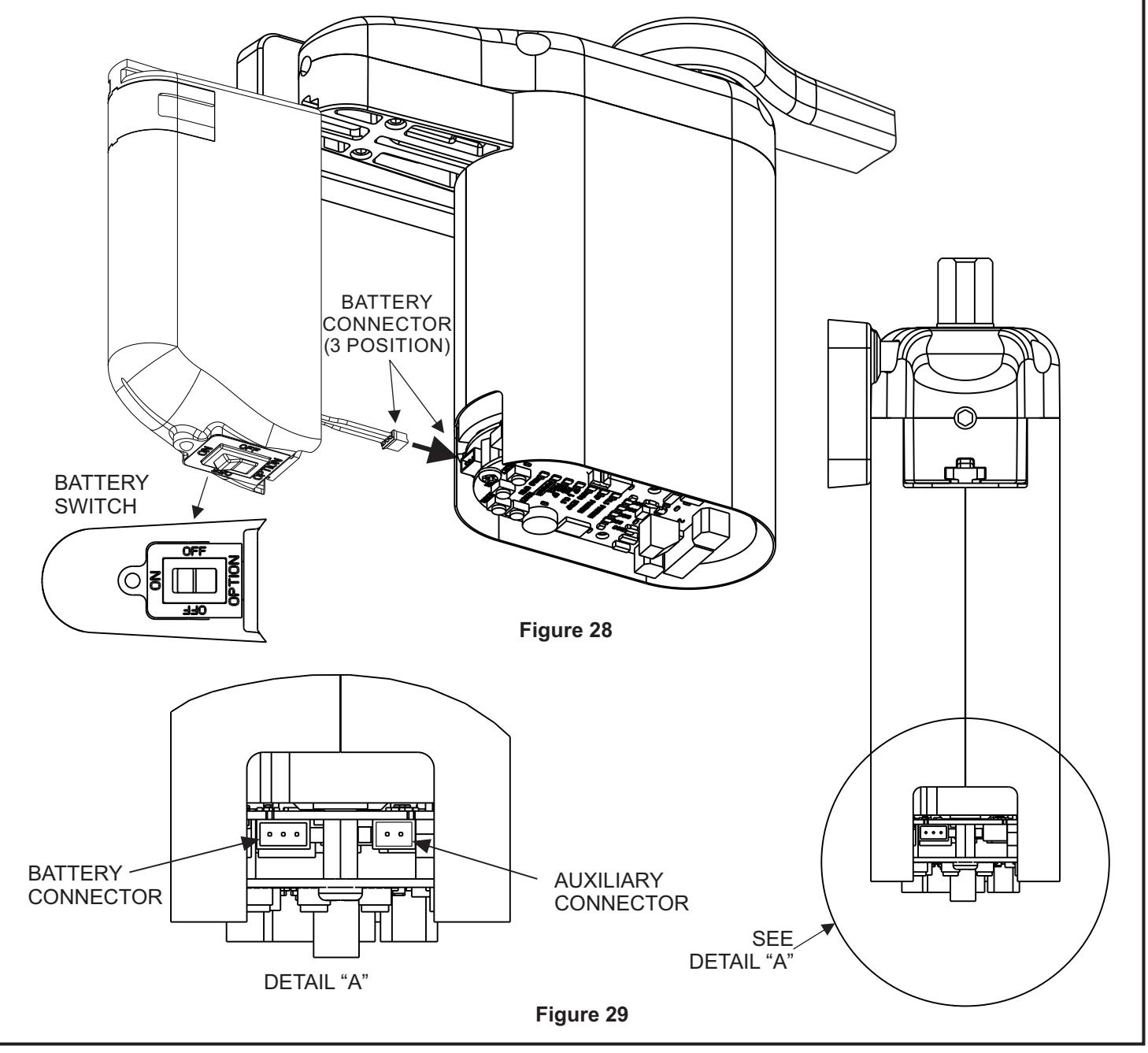
NOTE: There are two keyed connectors on the operator. One three-position connector accepts the battery pack connector plug.
- 1. Refer to Figure 28 and switch the ON/OFF/OPTION switch to the OFF position.
- 2. Refer to Figures 28 and 29, and CONNECT the battery pack connector plug to the operator.
- 3. SLIDE the battery pack onto the operator, and ENSURE that the battery pack wires do not interfere with the operator cover.
- 4. Change the ON/OFF/OPTION switch to the "ON" position.

USE 24VDC CLASS 2 TRANSFORMER ONLY Installing the Plug-In Transformer
NOTE: If possible, the transformer wiring should be routed against the door trim molding.
NOTE: An optional plug-in transformer is recommended in installations where the automatic door-opening feature will be used frequently. The optional plug-in transformer is REQUIRED for installations where Power Close and/or Push & Go features are enabled.
- 1. ROUTE transformer wiring to a 110-VAC outlet, but do not plug transformer into the outlet.
-
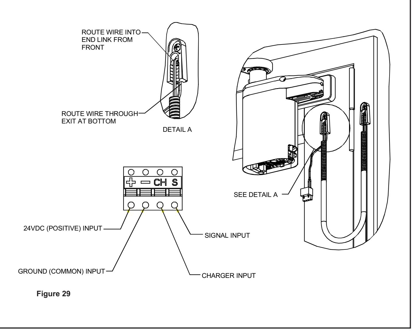
2. Refer to Figure 29, and ROUTE wires through armored cable end links. MOUNT the door cord end links as follows:
- MOUNT one end link in the area behind or next to the battery pack.
- MOUNT the other end link on or next to the door frame.
3. Refer to Figure 30, and PLUG connector into receptacle on battery pack.
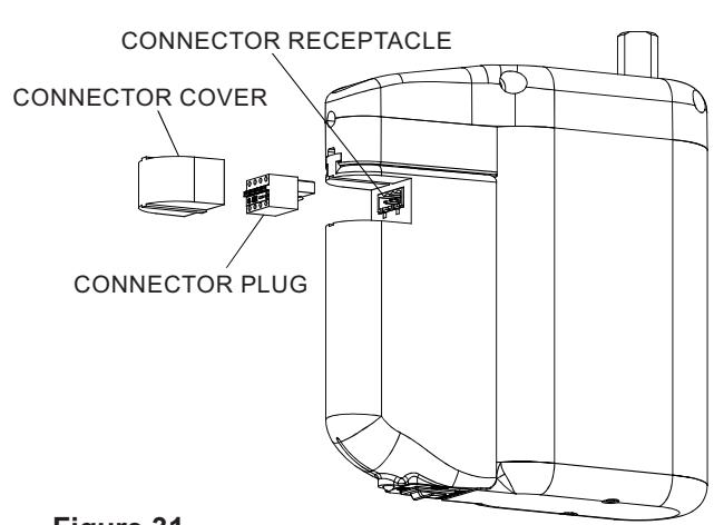
Figure 31
4. Refer to Figure 31, and VERIFY that the LED indicator lights GREEN.
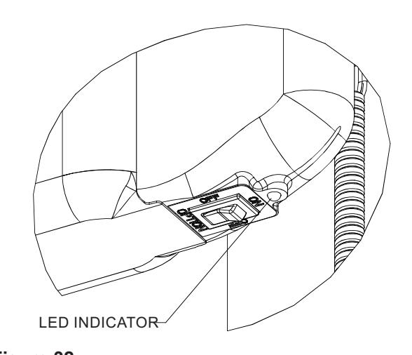
Figure 32
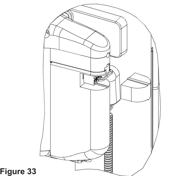
5. Refer To Figure 32, and INSTALL receptacle cover onto battery pack.
Checking Battery Voltage
-
1. Refer To Figure 3, and PRESS and HOLD the battery switch in the "OPTION" position. The following shall occur:
- The green LED shall illuminate to indicate that the battery pack is fully charged.
- The yellow LED shall illuminate to indicate that the battery is partially drained.
- The red LED shall illuminate to indicate that the battery pack is fully drained and the door operator will not function in the automatic mode.
Adjusting Door Spring Tension
NOTE: The doors are shipped with spring tension set to one half of the maximum spring tension.
- 1. Manually OPEN AND CLOSE the door several times. ENSURE that the door opens and closes smoothly.
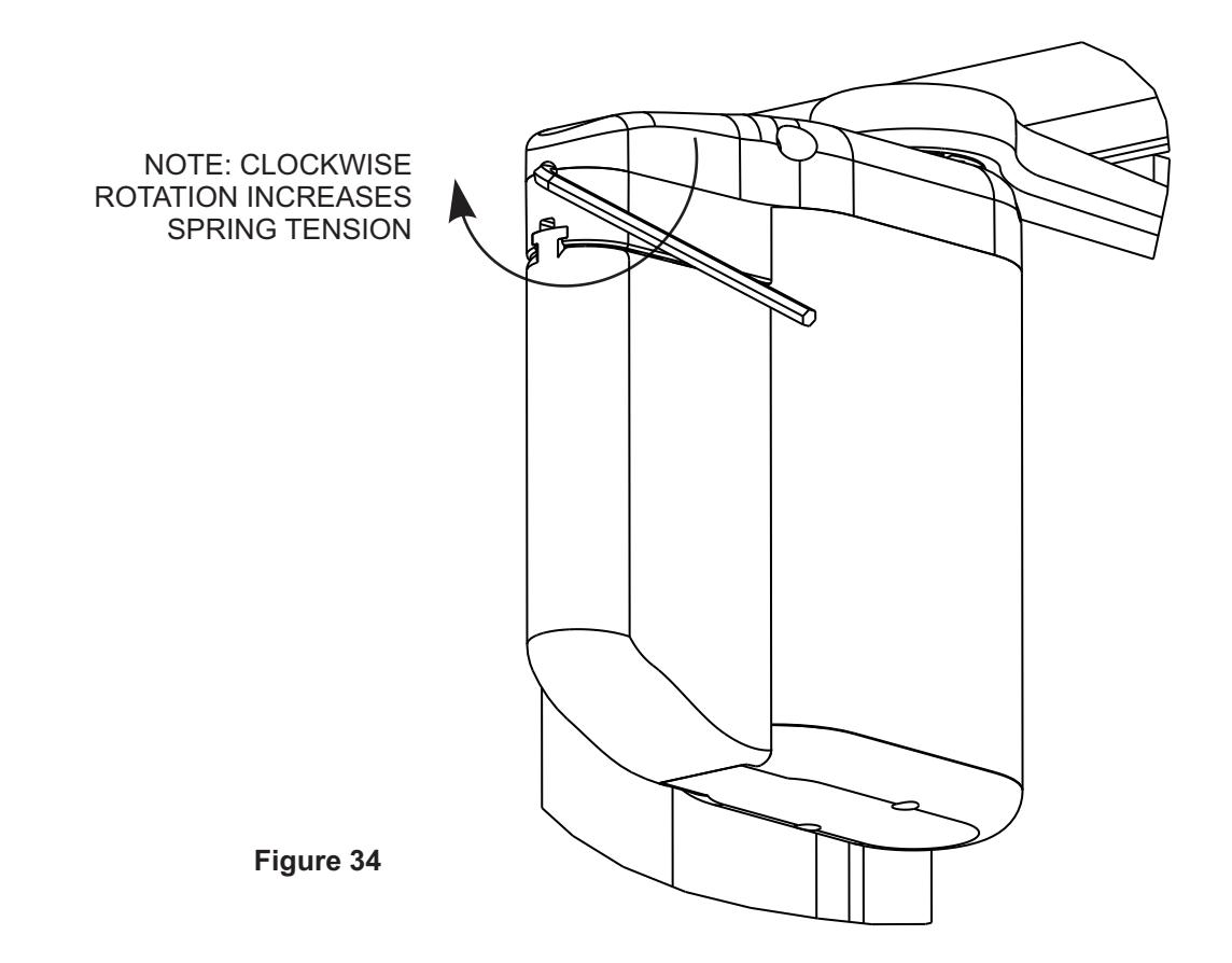
- 2. If the spring tension needs to be adjusted, refer to Figure 32, and ADJUST door-open spring tension as follows:
-
a. INSERT 3/16" hex wrench into spring tension setscrew.
- If the door feels too light, using the 3/16" hex wrench, TURN the setscrew in the end of the operator clockwise to increase spring tension.
- If the door feels too heavy, using 3/16" hex wrench, TURN the setscrew in the end of the operator counterclockwise to decrease spring tension.
9 Programming Instructions
Programming the Operator
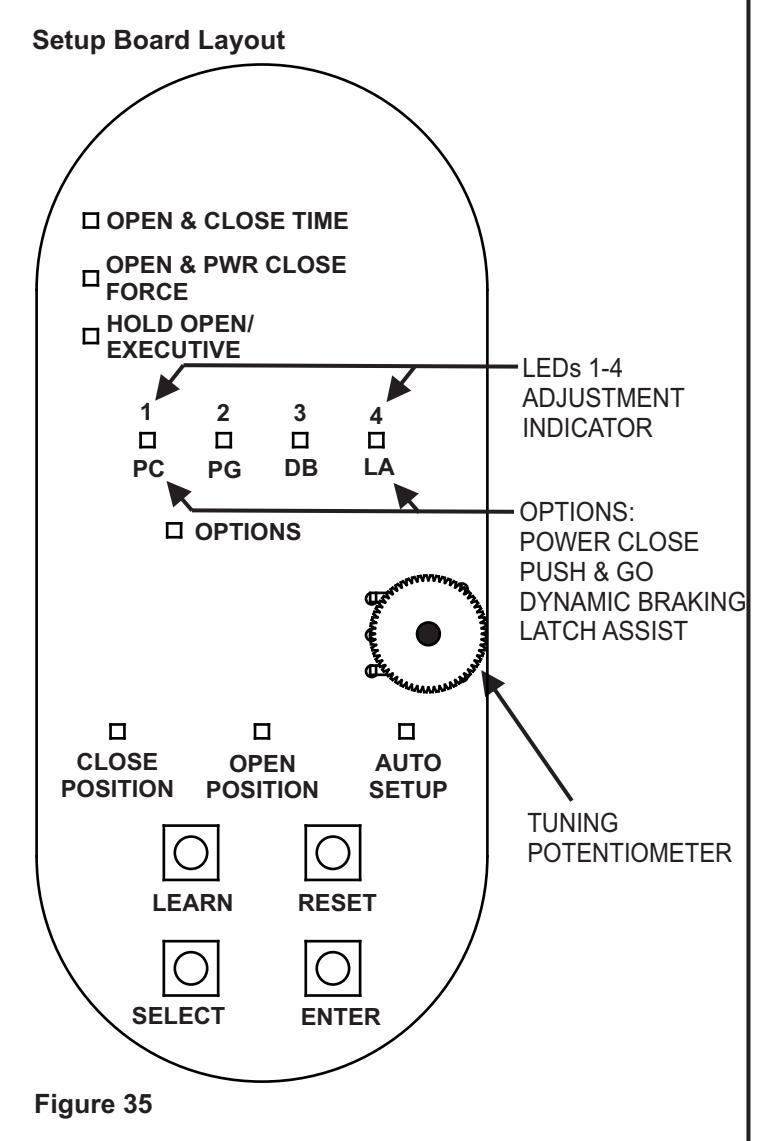
NOTE: The instructions programming the operator and linking the RF push buttons are common regardless of whether the door is a push or pull application. Refer to Figure 35 during programing for Setup Board Layout.
-
1. Enter programming mode, Refer to Figure 35 and, at the base of the setup board, PRESS and HOLD both "SELECT" and "ENTER" push buttons until LEDs 1 through 4 flash. The following shall occur:
- The operator shall enter program mode.
- The "CLOSE POSITION" LED shall illuminate red and remain lit.
-
2. Program Door Closed position, with the door in the closed position, PRESS and RELEASE the "ENTER" push button. The following shall occur:
- The "CLOSE POSITION" LED shall flash green briefly.
- The "OPEN POSITION" LED shall illuminate red.
-
3. Program Door open position, with the door in the fully open position, PRESS and RELEASE the "ENTER" push button. If the ENTER button is not accessible with the door in the fully open position, PRESS and RELEASE one of the activation push buttons. The following shall occur:
- The "OPEN POSITION" LED shall flash green briefly.
- The "AUTO SETUP" LED shall illuminate red.
-
4. Perform Auto-Setup, RETURN the door to the fully closed position, and PRESS and RELEASE the "ENTER" push button. The following shall occur:
- The door shall rapidly open 30 to 45 degrees and then close.
- The "AUTO SETUP" led shall illuminate green.
- The Operator will exit programming mode.
- 5. If further door adjustments are desired or optional features will be enabled refer to Section 11, and PERFORM adjustments.
-
6. To reset the controller, PERFORM the following:
- PRESS and HOLD the "ENTER" button,
- While holding down the "ENTER" button PRESS and RELEASE the "RESET" button.
- LEDs 1 through 4 shall flash green briefly
NOTE: Resetting the controller does not reset the RF transmitters.
5800 Series Low Energy Operator Installation and Operation Instructions

10 Linking the RF Push Buttons
Linking the RF Push Buttons
NOTE: Only 5800 transmitters can be linked to the RF receiver of the operator.
Only one 5800 transmitter can be programmed at a time. The procedure below can be repeated for up to twelve 5800 transmitters. This RF push button linking method does not overwrite other RF controls previously programmed into memory.
-
1. To link an RF switch with a door controller PRESS and HOLD the "LEARN" push button on the controller until LEDs 1 through 4 flash green.
- b. PUSH the RF push button. LED "CLOSE POSITION" shall flash green indicating that the operator accepted this RF push button.
- c. REPEAT as necessary for additional 5800 transmitters.
-
2. To remove all RF push buttons from memory, PERFORM the following:
- PRESS and HOLD the "LEARN" push button on the controller,
- While holding down the "LEARN" push button, PRESS and RELEASE the "RESET" push button.
- RELEASE the "LEARN" push button.
11 Customizing Operator Settings (Optional)
NOTE: The parameters for OPEN and CLOSE TIME, OPEN & POWER CLOSE FORCE, and HOLD-OPEN TIME are preset to comply with ANSI standards for low-energy operators but may be adjusted if approved by the Authority Having Jurisdiction (AHJ).
Before attempting any changes to these settings, be sure the Auto-Tune process has been successfully completed.
- 1. PRESS and HOLD the "SELECT" and "ENTER" push buttons for three seconds to enter programming mode. LEDs 1 through 4 shall flash green briefly.
- The "OPEN & CLOSE TIME" LED shall illuminate.
- 3. PRESS and RELEASE the "SELECT" push button until the LED next to the setting to be modified lights.
NOTE: The LED bar will indicate the previously set value until the POTENTIOMETER is rotated.
4. With the desired LED illuminated, ROTATE the thumbwheel to adjust the corresponding setting. Refer to table 2 for approximate adjustment values.
NOTE: Verify adjustments using a stop watch and force gauge.
- 5. PRESS and RELEASE "ENTER" push button to store that value.
- 6. PRESS and HOLD the "ENTER" push button for three seconds. The operator shall exit programming mode.
NOTE: The LED bar will indicate minimum and maximum values as adjustments are made. Green indications are within ANSI standards. Red indications exceed ANSI standards.
OPEN & CLOSE TIME range is 2.5 to 9 seconds (open and close times are calculated during the autosetup process).
OPEN & PWR CLOSE FORCE adjusts the force the operator will apply in the open direction. If the optional power close feature is turned on the power close force will be adjustable using this setting.
HOLD OPEN time range is 1 to 30 seconds (default = 5 seconds).
EXECUTIVE MODE requires an activation to open the door and a second activation to close the door.
7. TEST operator to confirm desired results. If necessary, REPEAT adjustment.

11 Customizing Operator Settings (Optional)
Table 1 Door Open & Close Time in seconds
| Door Weight (Pounds) | Door Width (Inches) | |||||
|---|---|---|---|---|---|---|
| 36 | 38 | 40 | 42 | 44 | 48 | |
| 50 | 3.0 | 3.0 | 3.0 | 3.0 | 3.0 | 3.0 |
| 75 | 3.0 | 3.0 | 3.0 | 3.0 | 3.0 | 3.1 |
| 100 | 3.0 | 3.0 | 3.0 | 3.2 | 3.3 | 3.6 |
| 150 | 3.3 | 3.5 | 3.7 | 3.9 | 4.1 | 4.4 |
| 200 | 3.8 | 4.0 | 4.3 | 4.5 | 4.7 | 5.1 |
| 250 | 4.3 | 4.5 | 4.8 | 5.0 | 5.2 | 5.7 |
Table 2 Time and Force Settings
| LED | OPEN FORCE | POWER CLOSE FORCE | ||||||||||
|---|---|---|---|---|---|---|---|---|---|---|---|---|
| Setting | 1 | 2 | 3 | 4 |
Open/Cls
Time |
Hold Open |
36" Door
Force |
42" Door
Force |
48" Door
Force |
36" Door
Force |
42" Door
Force |
48" Door
Force |
| 1 | GRN | OFF | OFF | OFF | 2.5 | 1 | 7 | 6 | 5 | 14 | 12 | 10 |
| 2 | OFF | GRN | OFF | OFF | 3.5 | 2 | 9 | 8 | 7 | 14 | 12 | 10 |
| 3 | OFF | OFF | GRN | OFF | 4 | 3 | 12 | 10 | 9 | 15 | 13 | 11 |
| 4 | OFF | OFF | OFF | GRN | 4.5 | 5 | 15 | 13 | 11 | 16 | 14 | 12 |
| 5 | GRN | GRN | OFF | OFF | 5 | 7 | 17 | 15 | 13 | 18 | 15 | 13 |
| 6 | GRN | OFF | GRN | OFF | 6 | 10 | 19 | 16 | 14 | 19 | 16 | 14 |
| 7 | GRN | OFF | OFF | GRN | 7 | 15 | 21 | 18 | 16 | 20 | 17 | 15 |
| 8 | GRN | GRN | GRN | OFF | 7.5 | 20 | 23 | 20 | 17 | 21 | 18 | 16 |
| 9 | GRN | GRN | OFF | GRN | 8 | 25 | 25 | 21 | 19 | 23 | 20 | 17 |
| 10 | GRN | GRN | GRN | GRN | 9 | 30 | 30 | 26 | 22 | 25 | 21 | 19 |
| 11 | RED | RED | RED | RED | N/A |
EXECUTIVE
MODE |
N/A | N/A | N/A | N/A | N/A | N/A |
5800 Series Low Energy Operator Installation and Operation Instructions

12 Setting Optional Functions (Power Close, Push & Go, Dynamic Braking, Latch Assist)
NOTE: The 5800 must be plugged in to the 24VDC Class 2 transformer if the POWER CLOSE, PUSH & GO, or LATCH ASSIST features are enabled.
POWER CLOSE will apply a closing force on the door if the door did not fully close in the normal closing time. Power close will activate and turn off when the door is fully closed or if the door does not move after attempting to close for two seconds.
PUSH & GO will cause the door operator to initiate an automatic open cycle when the door is pushed in the open direction.
DYNAMIC BRAKING will apply braking to the door when the door speed exceeds four times the programed automatic opening time under abusive opening conditions or wind.
LATCH ASSIST will apply a force in the close direction for 1/2 second when the operator receives an activate signal to assist an electric strike in unlocking. When the door closes the operator will apply a force in the close direction to assist in latching the door.
-
1. ENABLE or DISABLE Power Close, Push & Go, Dynamic Braking, or Latch Assist (factory default is OFF for all features):
- a. PRESS and HOLD "SELECT" and "ENTER" until LEDs 1 through 4 flash green briefly.
- The "OPEN & CLOSE TIME" LED shall illuminate.
- b. PRESS and RELEASE the "SELECT" push button to advance until OPTIONS LED illuminates and the LED above the desired function lights.
-
PC LED indicates POWER CLOSE
- PG LED indicates PUSH & GO
- DB LED indicates DYNAMIC BRAKING
- LA LED indicates LATCH ASSIST
NOTE: The LED color indicates the state of the selected setting until the POTENTIOMETER is rotated. A GREEN LED indicates the features is turned ON and a RED LED indicates the feature is OFF.
- c. ROTATE the potentiometer to change the state of the LED. The green LED shall illuminate to indicate that Power Close function is ON. The red LED shall illuminate to indicate that the Power Close function is OFF.
- d. PRESS and RELEASE the "ENTER" push button to store the setting.
- e. PRESS and HOLD the "ENTER" push button for three seconds. The operator shall exit programming mode.
- f. PRESS and HOLD the "ENTER" push button for three seconds. The operator shall exit programming mode.

13 Closeout Instructions
Closeout Procedure
- 1. Refer to Figure 36, and INSTALL door decals.
- 2. IF PUSH & GO is enabled, APPLY "PUSH TO OPERATE" and "PULL TO OPERATE" labels as shown in Figure 36.
- 3. ENSURE all connectors are secure.
- 4. ENSURE all wires are secured and hidden where possible.
- 5. ENSURE the operator dress cover is installed and secure.
- 6. ENSURE the controller cover is installed and secure.
- 7. ENSURE the door and door trim surfaces are clean.
- 8. ENSURE the door installation area is clean and free of debris.
- 9. ENSURE that the client/resident is instructed on how to operate the product correctly, and understands how to perform the daily safety check.
- 10. COMPLETE Work Order and REPORT your actions to Building Superintendent.
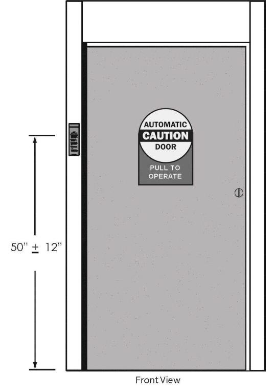
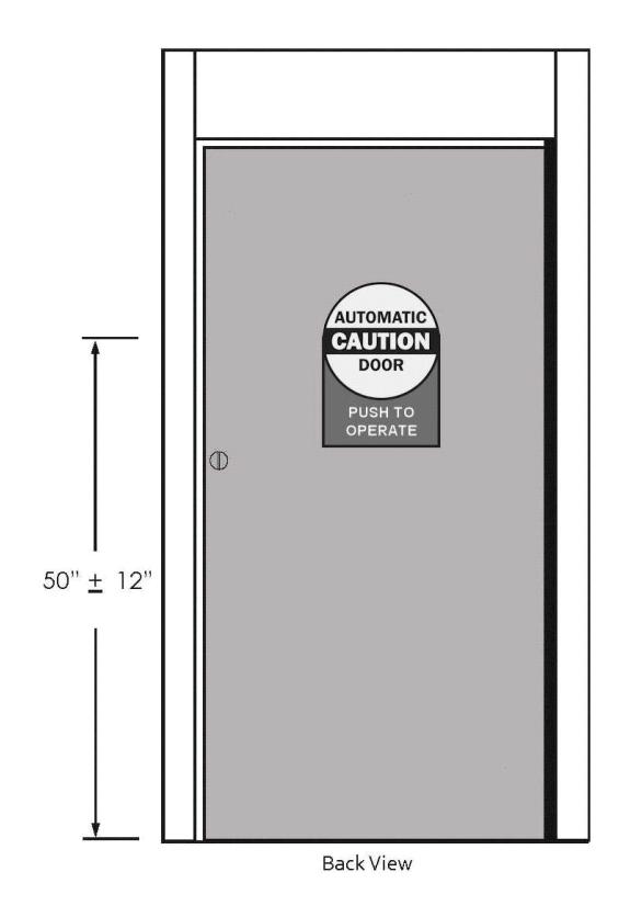
Figure 36

14 Troubleshooting
| Recommended Remedy |
|---|
|
Refer to section titled "Adjusting Door Spring Tension" and reduce the
door-open spring tension. |
|
Refer to section titled "Installing the Operator Mounting Bracket" and lower the
bracket mounting position. |
|
Ensure that the operator is mounted parallel to the face of the door. If the
bottom of the operator is further away from the door than the top, shim the top of the operator mounting bracket to compensate. |
|
Refer to section titled "Installing the Door Arm" and ensure that the door arm
coupling screws are tightened evenly (one quarter turn at a time) until fully tight. |
|
• Ensure the On/Off/Option switch on the bottom of the battery pack is in the
"ON" position. • Refer to figure titled "Connecting the Battery Pack" and ensure the battery is properly connected to the operator. • Refer to section titled "Initializing the Remote Control" and program the RF push button switch. • Refer to section titled "Programming the Operator" and program the operator. • To verify a low voltage battery condition perform the following: o Put and hold the On/Off/Option switch in the OPTION position. o Observe the LED indicator on the bottom of the battery pack • If the LED is GREEN the voltage is good (above 22.5VDC). • If the LED is YELLOW the voltage is nominal (above 18.5VDC but below 22.5VDC) • If the LED is RED the battery pack is exhausted (below 18.5VDC) and must be charged o Battery can be charged by using a battery charger or a plug in 24VDC Class 2 transformer or by allowing manual traffic to restore battery power. |
|
• Refer to section titled "Programming the Operator" and Auto-Setup the
operator. • Refer to section titled "Adjusting the Door for Proper Operation" and adjust the door hold open time. |
|
• Refer to section titled "Programming the Operator" and Auto-Setup the
operator. • Refer to section titled "Customizing Operator Settings" and adjust the door hold open time. |
|
• Refer to section titled "Programming the Operator" and Auto-Setup the
operator. • Refer to section titled "Customizing Operator Settings" and adjust the door hold open time. |

14 Troubleshooting
| Symptom | Recommended Remedy |
|---|---|
| Door Opens Too Slow |
• Refer to section titled "Programming the Operator" and Auto-Setup the
operator. • Refer to section titled "Customizing Operator Settings" and adjust the door hold open time. |
| Door Closes Too Fast |
• Refer to section titled "Programming the Operator" and Auto-Setup the
operator. • Refer to section titled "Customizing Operator Settings" and adjust the door hold open time. |
| Door Closes Too Slow |
• Refer to section titled "Programming the Operator" and Auto-Setup the
operator. • Refer to section titled "Customizing Operator Settings" and adjust the door close time. |
| Door Opening Force Too High |
• Refer to section titled "Programming the Operator" and Auto-Setup the
operator. • Refer to section titled "Customizing Operator Settings" and adjust the door open force. |
|
Can't Remove Battery
From Housing |
• Refer to Figure 29, and note the T-shaped channel at the top of battery
housing. • Insert a small flat head screwdriver into the slot above the T-channel and gently pry the battery from the operator housing. |
| Can't Initialize RF Buttons |
• Verify that the CR2032 battery installed in the RF transmitter is good by
ensuring voltage is 2.8VDC or greater. • Refer to section titled "Linking the RF Push Buttons" and erase all activation codes. THEN: • Set and RF switch with a door controller following the instructions in the section titled "Linking the RF Push Buttons." • Loosen the nuts on the back of the switch plate assembly to ensure that the switch is not stuck in the closed position. |
| Door Stays Open at 90 Degrees |
• Door arm has slipped on the output shaft.
o Refer to section titled, "Installing the Door Arm." o Refer to Figure 15 (push side application) or 26 (pull side application). o Loosen the three door arm coupling screws. o Ensure the door arm is touching the face of the door. o Tighten the door arm coupling screws evenly (one quarter turn at a time) until fully tight. Be sure screws are tightened securely. • Door arm end link washer has not been installed. o Refer to Figure 17. o Install supplied washer. (Two are supplied; only one is required.) • Door arm rubs on door arm pivot bracket. o Refer to Figures 13 (push side application) and lower door operator using the slotted mounting holes in the mounting bracket. |

11 Troubleshooting
| Symptom | Recommended Remedy | ||||
|---|---|---|---|---|---|
|
Door Stays Open at 90 Degrees
Con't |
o Ensure that the operator is mounted parallel to the face of the door.
o If the bottom of the operator is further away from the door than the top, shim the top of the operator mounting bracket to compensate. • Spring force set too low. o Refer to section titled, "Adjusting Door Spring Tension." o Refer to Figure 34. o Increase spring force – note operators are shipped from factory at one half of maximum spring tension. • Spring pre-load set too high o Refer to section titled, "Installing the Door Arm." o Remove door arm from the door arm pivot assembly. o Decrease pre-load by rotating the door arm end link counterclockwise. o Note making the door arm longer decreases preload. • Door arm pivot bracket too close to door face o Refer to section titled, "Installing to Door Arm Pivot Bracket." o Increase the 6-3/8" (161.92 mm) dimension shown below to 6-1/2" (165.1 mm). |
||||
|
Door Stays Open at 90 Degrees
Only When Power Operated |
• Refer to section titled, "Programming the Operator," and perform a retune. | ||||
|
When Used Manually the Door
Arm Reverses and Does Not Allow the Door to Close |
• Door arm has slipped on the output shaft.
o Refer to section titled, "Installing the Door Arm." o Loosen the three door arm coupling screws. o Ensure the door arm is touching the face of door. o Tighten the door arm coupling screws evenly (one quarter turn at a time) until fully tight. Be sure screws are tightened securely. • Refer to section titled, "Programming the Operator," and perform a retune. |
||||
| Door Will Not Fully Close |
• Ensure door can open and close freely and there is no obstruction.
•Refer to section titled "Adjusting Door Spring Tension" and increase the door open spring tension. The operator must only be installed on doors and frames in good working order, without sticking or binding during normal operation. • Door arm has slipped on the output shaft. o Refer to section titled, "Installing the Door Arm." o Refer to Figure 15 (push side application) or 26 (pull side application). o Loosen the three door arm coupling screws. o Ensure the door arm is touching the face of the door. o Tighten the door arm coupling screws evenly (one quarter turn at a time) until fully tight. Be sure screws are tightened securely. • If the unit is powered with the hardwire kit, refer to section titled "Setting Optional Functions" and turn on Power Close. |
||||
5800 Series Low Energy Operator Installation and Operation Instructions


1. Documents, Definitions, Tools, Equipment, and Consumables (Sheet 1 of 1)
Documents
ANSI A156.19-2007, "American National Standard for Power Assist and Low Energy Power Operated Doors"
ANSI A117.1-2008, "Standard on Accessible and Usable Buildings and Facilities"
Definitions
AHJ: Authority Having Jurisdiction
LED: Light-emitting diode
Consumables (including, but not limited to)
Clean rags Glass cleaner
Notes
- Optional battery charger p/n 1023P (not provided). Use 24VDC Class 2 Transformer Only.
- Transmitter battery: 3 volt, 280 mAH, Lithium, part number CR2032
The 5800 utilizes a lithium-polymer main battery. Please return all discharged batteries to Norton Rixson Door Controls.
Tools and Equipment (including, but not limited to)
Adjustable Wrench Box Wrench 7/16″ Rivnut installer Wire cutters*
Combination square Drill bit sizes: 25/64", 5/32"
Safety glasses Screwdriver kit Wire strippers*
Electric drill, metal drill bit set, concrete drill bit set
Scribe or center punch
Hammer Staple gun* Hex wrench set
Hex wrench sizes: 3/16", 9/64", 1/16"
Tape
Tape measure
*Needed if installing the optional transformer.


2. Quick Programming Guide (Sheet 1 of 1)
| Step | Operator Action | Response | ||||
|---|---|---|---|---|---|---|
| Programming the door operator | ||||||
| 1. |
Refer to Figure 36 and, at the base of
the controller, PRESS and HOLD the "SELECT" and "ENTER" until LEDs 1 through 4 flash. |
• The operator shall enter program mode.
• The four LEDs on the circuit board shall repeatedly flash green. • The "CLOSE POSITION" LED shall illuminate red and remain lit. |
||||
|
NOTE: The doors are shipped with a spring tension set to one half of maximum spring tension.
Always reprogram the operator after adjusting the door spring tension. |
||||||
| 2. |
With the door in the closed position,
PRESS the "ENTER" push button. |
• The "CLOSE POSITION" lED shall flash green.
• The "OPEN POSITION" LED shall illuminate red indicating that the operator is ready for input. • The LED shall illuminate green once data has been stored for this parameter. |
||||
| 3. | Open the door to its fully open position. | |||||
| 4. |
With the door in the fully open
position, PRESS the "ENTER" push button. |
• The "OPEN POSITION" LED shall flash green.
• The "AUTO SETUP" position LED shall illuminate red indicating that the operator is ready for input. • The LED shall illuminate green once data has been stored for this parameter. |
||||
| 5. |
With the door in the fully closed
position, PRESS the "ENTER" push button. |
• The door shall open quickly and then close slowly.
• The "AUTO SETUP" led shall illuminate green. • The operator will store the settings and exit programming mode. |
||||
| 6. |
To reset the controller, PERFORM the following:
a. PRESS and HOLD the "ENTER" push button. b. PRESS and RELEASE the "RESET" push button. c. RELEASE the "ENTER" push button. |
|||||
| 7. | If further door adjustments are necessary, refer to Sections 9 through 12 and PERFORM adjustment. | |||||
| Initializing the Remote Control | ||||||
| 1. |
To set RF switch with door controller,
PERFORM the following: |
|||||
| a. PUSH the "LEARN" switch on the controller. |
The controller will enter the learn mode for 15
seconds while green and red LEDs are illuminated. |
|||||
| b. PUSH the RF activation switch. |
LED "CLOSE POSITION"shall flash green
indicating that the operator learned this RF |
|||||
| 2. |
To erase all activation codes learned in door controller,
PERFORM the following: |
|||||
| a. Press and hold the "LEARN" switch on the operator. | ||||||
| b. Press and release the "RESET" switch on the operator. | LED 1 through 4 will flash green. | |||||
| c. Release the "LEARN" switch. | ||||||

A
Attachments
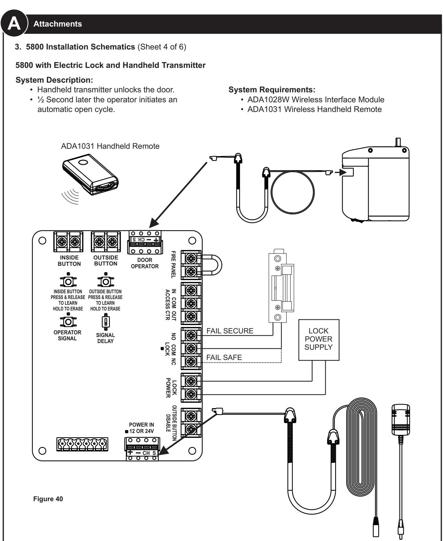
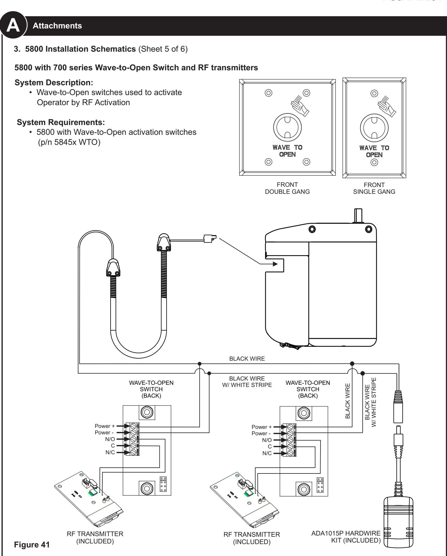
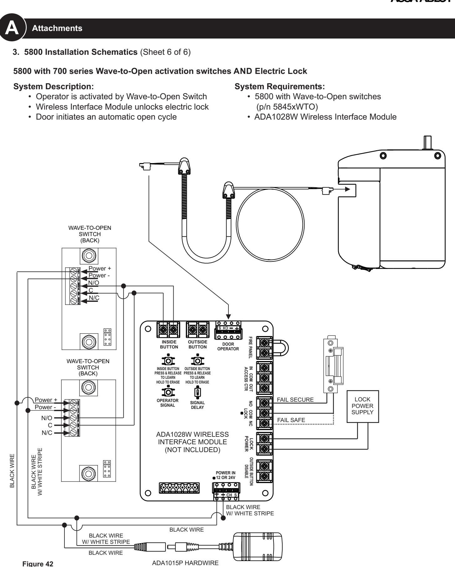
3. 5800 Installation Schematics (Sheet 1 of 6)
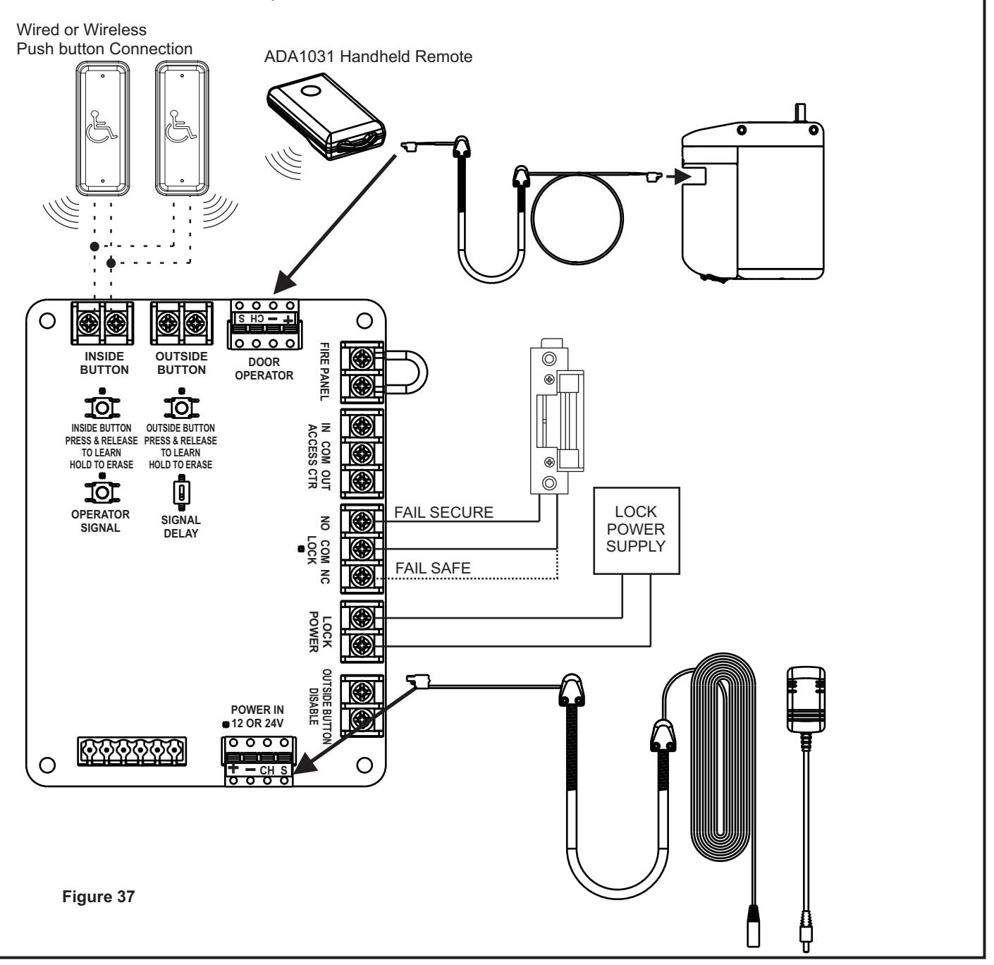
5800 with Electric Strike and wired OR wireless Buttons and/or Handheld Remote
System Description:
- 5800 with 12 or 24VDC power supply (by other) with Wireless Buttons.
- Pressing either inside, outside push button, or handheld remote activates electric lock then
- Door operator initiates and automatic open cycle after a selectable time delay.
System Requirements:
- 1x ADA1028W Wireless Interface Module
- 1x ADA1031 Wireless Handheld Remote
- 12/24VDC Power Supply and electric lock (BY OTHERS)

Attachments
3. 5800 Installation Schematics (Sheet 2 of 6)
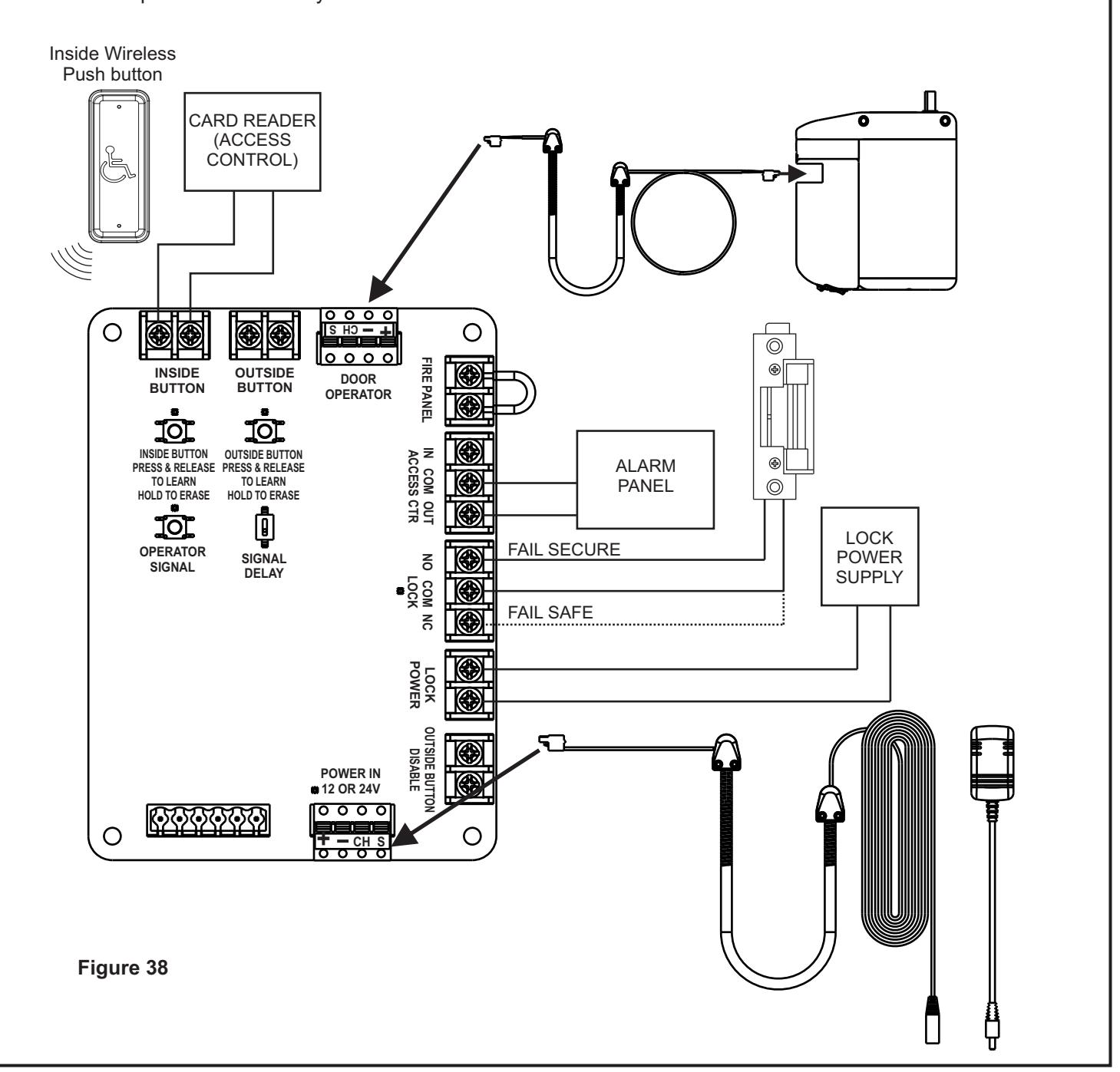
5800 with Electric Lock and Access Control Panel - No Outside Button
System Description:
- A valid card presented to the reader will unlock the door and initiate an automatic open cycle.
- 5800 Hardwired kit (p/n ADA1015P) is REQUIRED.
- Inside push button is always enabled.
System Requirements:
- 1x ADA1028W Wireless Interface Module
- 1x ADA1012-2 Rectangular Push Button with RF transmitter
- · Access Control BY OTHERS


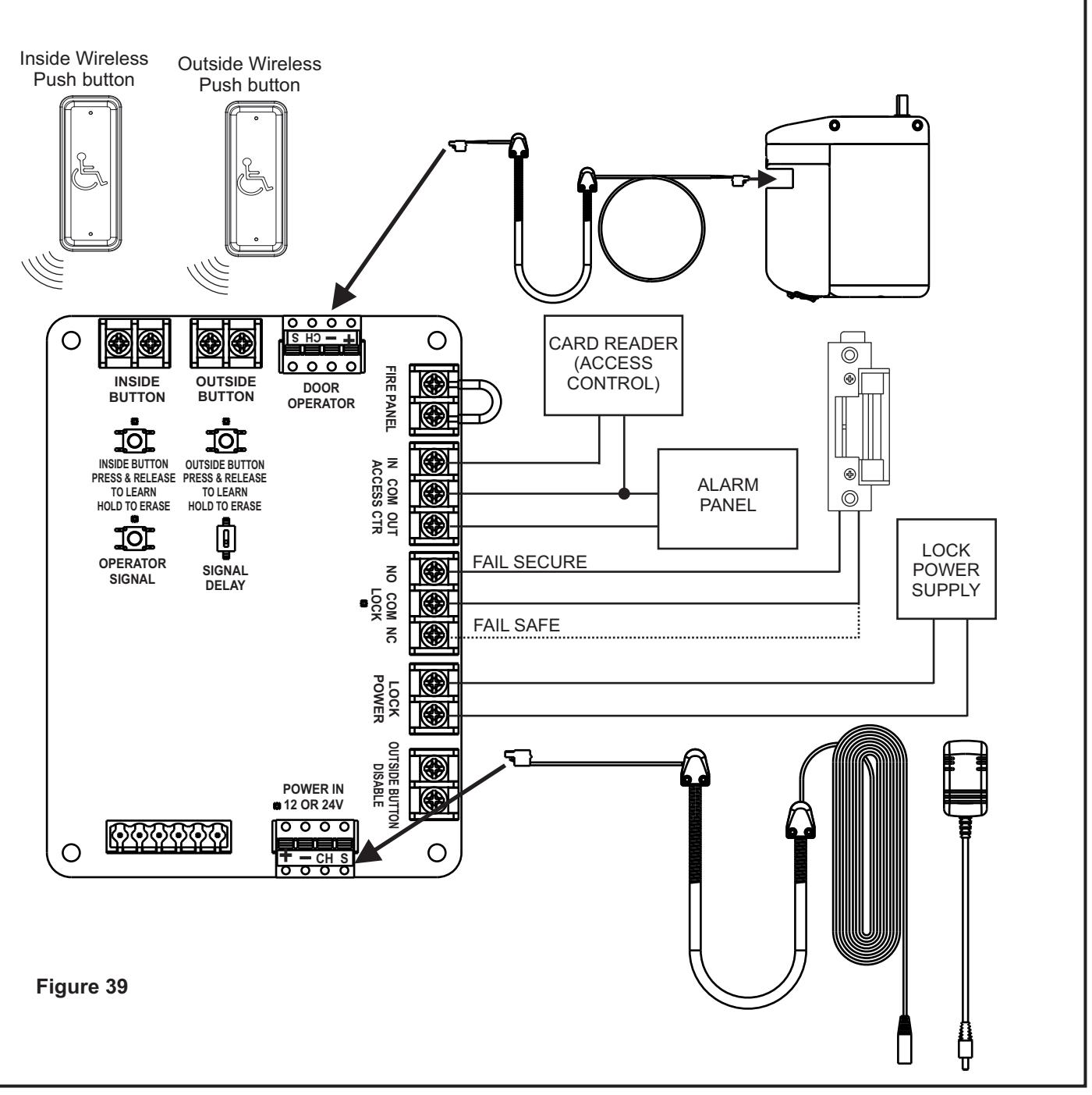
3. 5800 Installation Schematics (Sheet 3 of 6)
5800 with Electric Lock and Access Control Panel
System Description:
- Outside Push button is enabled when a valid card is presented to the reader.
- · Inside Push button is always active.
System Requirements:
1x ADA1028W Wireless Interface Module



KIT (INCLUDED)
The ASSA ABLOY Group is the global leader in access solutions. Every day we help people feel safe, secure and experience a more open world.

A
Attachments
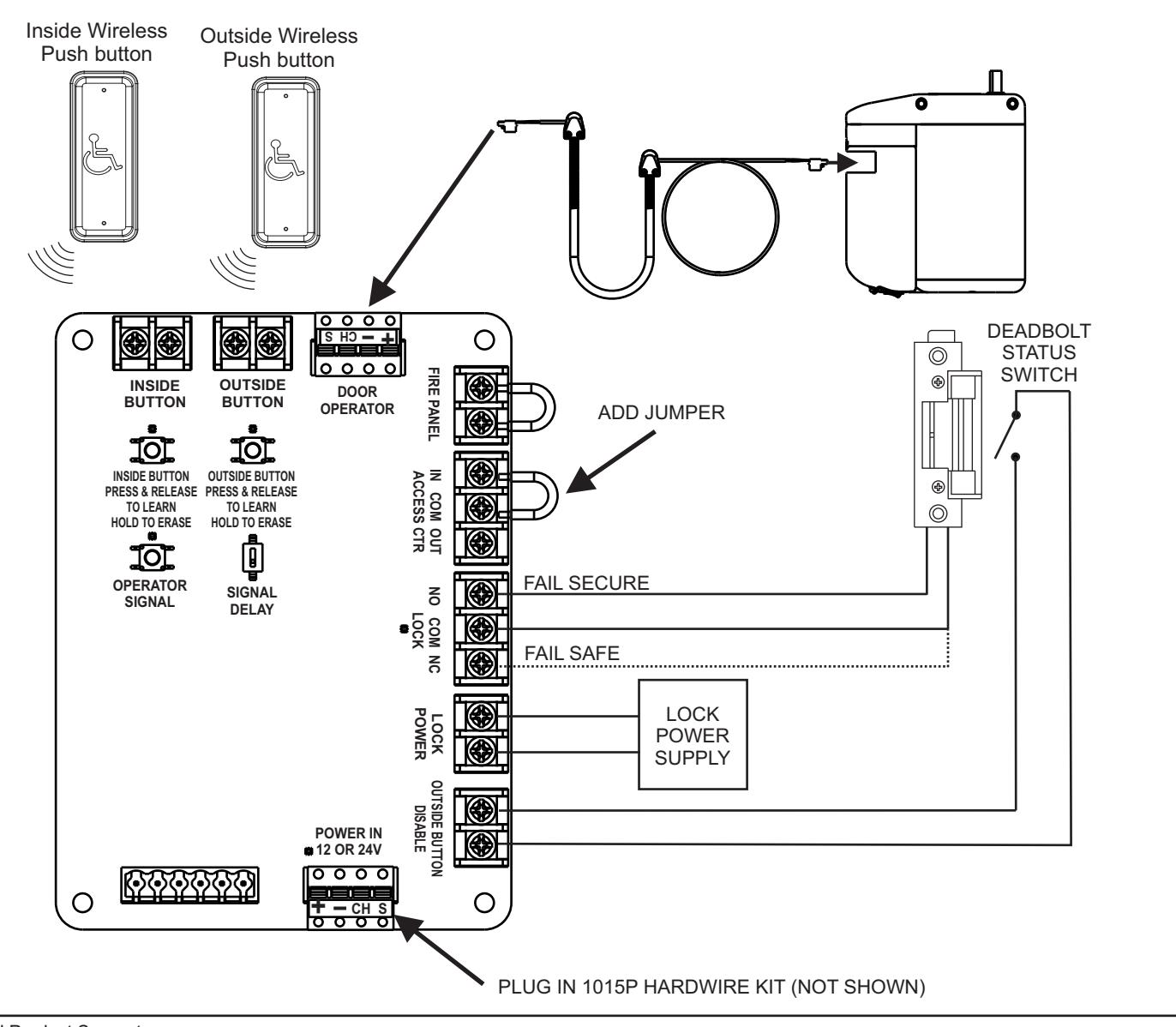
3. 5800 Installation Schematics (Sheet 3 of 6)
5800 with Electric Lock and Disable Push Button Switch
System Description:
- Electric strike is NORMALLY UNLOCKED unless Deadbolt is thrown to activate Outside Push button Disable using Deadbolt Status Switch.
- · Inside Push button is always active.
System Requirements:
- 1x ADA1028W Wireless Interface Module
- Deadbolt Status Switch
Technical Product Support: Monroe, NC 28112 USA Phone: 877.974.2255 ext: 2
Techsupport.NortonRixson@assaabloy.com
NortonRixson.com