Norton Rixson 4500 Series Power Operator Programming Instructions_80-9345-0003-020
Open the original PDF document
View PDF4500 Series Power Operator Programming Instructions



WARNING
This product can expose you to lead which is known to the state of California to cause cancer and birth defects or other reproductive harm. For more information go to www.P65warnings.ca.gov.
Pour la version francaise voir www.nortonrixson.com. READ AND FOLLOW ALL INSTRUCTIONS. SAVE THESE INSTRUCTIONS.
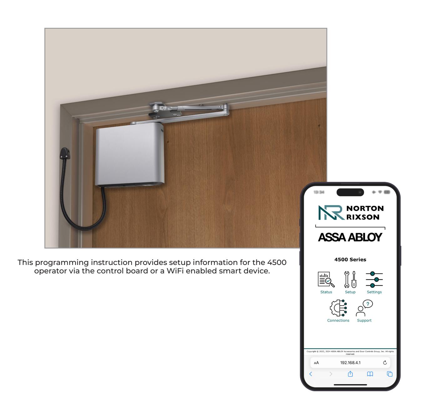

Contents
| Initial Operator Setup 3 | |
|---|---|
|
Operator Setup via the Control Board
|
3 |
| Operator Setup via WiFi 4 | |
| Connections | 7 |
| Input Connections7 | |
| Output Connections . | 7 |
| RF Input | 8 |
|
Wiring Diagrams
|
9 |
| Example 1: Standard Activation . | 9 |
| Example 2: Push/Pull with Deadbolt . | 10 |
| Example 3: Fail Secure Electric Strike | 11 |
| Example 4: Fail Safe Electric Strike 12 | |
| Troubleshooting and Support . | 13 |
| Appendix A: Physical Interface | 14 |
| Control Board | 14 |
| Input/Output (I/O) Board 15 | |
| Appendix B: WiFi Interface16 | |
| Home Page | 16 |
| Status Page | 16 |
| Operator Setup Page | 17 |
| Settings Page | 18 |
| Connections Page . | 20 |
| Support Page 21 |
FCC:
Class B Equipment
This equipment has been tested and found to comply with the limits for a Class B digital device, pursuant to Part 15 of the FCC Rules. These limits are designed to provide reasonable protection against harmful interference in a residential installation. This equipment generates, uses and can radiate radio frequency energy and, if not installed and used in accordance with the instructions, may cause harmful interference to radio communications. However, there is no guarantee that interference will not occur in a particular installation. If this equipment does cause harmful interference to radio or television reception, which can be determined by turning the equipment off and on, the use is encouraged to try to correct the interference by one or more of the following measures:
- Reorient or relocate the receiving antenna.
- Increase the separation between the equipment and receiver.
- Connect the equipment into an outlet on a circuit different from that to which the receiver is connected.
- Consult the dealer or an experienced radio/TV technician for help.
This device complies with Part 15 of the FCC Rules. Operation is subject to the following two conditions: (1) This device may not cause harmful interference, and (2) this device must accept any interference received, including interference that may cause undesired operation.
Warning:
Changes or modifications to this device may void the user's authority to operate the equipment.
Industry Canada:
This Class A digital apparatus meets all requirements of the Canadian Interference Causing Equipment Regulations.
Cet appareillage numérique de la classe A répond à toutes les exigences de l'interférence canadienne causant des règlements d'équipement.
Declaración de México:
La operación de este equipo está sujeta a las siguientes dos condiciones: (1) es posible que este equipo o dispositivo no cause interferencia perjudicial y (2) este equipo o dispositivo debe aceptar cualquier interferencia, incluyendo la que pueda causar su operación no deseada.

Initial Operator Setup
Programming should be initiated after initial operator installation has been completed.
Operator Setup via the Control Board
After the operator has been successfully installed and power has been applied, perform the following steps to program the 4500 Operator via the Control Board.
For definitions of the function buttons and LEDs on the Control and Input/Output Boards of the 4500 Operator, refer to Appendix A on page 14.
NOTE: Setup can alternatively performed via Wifi interface. Refer to pages 4 and 5.
A. Set the door open and close positions:
Set the closed position :
- 1. Fully close the door.
-
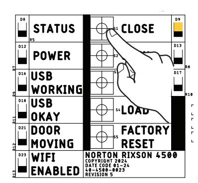
2. Press and release the CLOSE button on the control board.
- ‒ The yellow CLOSE LED will change from flashing to solid. (Figure 1)
NOTE: When the door is in the closed position, the yellow LED will illuminate solid.
Set the open position :
-
1. Manually open door to its fully open position (90° or less).
- ‒ The green OPEN LED will begin flashing.
NOTE: If there is a wall or door stop at the fully open position, hold the door slightly away from wall or stop.
-
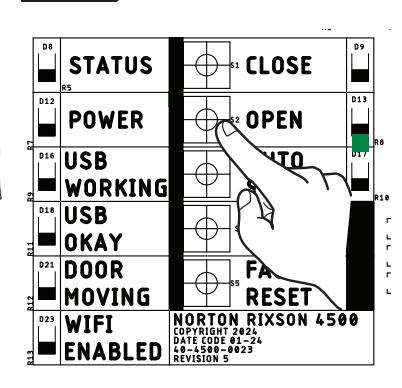
2. With the door in the open position, press and release the OPEN button on the control board.
- ‒ The flashing green OPEN LED will turn solid once the position has been set. (Figure 2)
NOTE: When the door is in the fully open position, the green LED will illuminate solid.
Run Auto Setup :
- 1. Manually close the door. Once fully closed, confirm there are no obstructions or latching hardware that could prevent the door from opening.
-
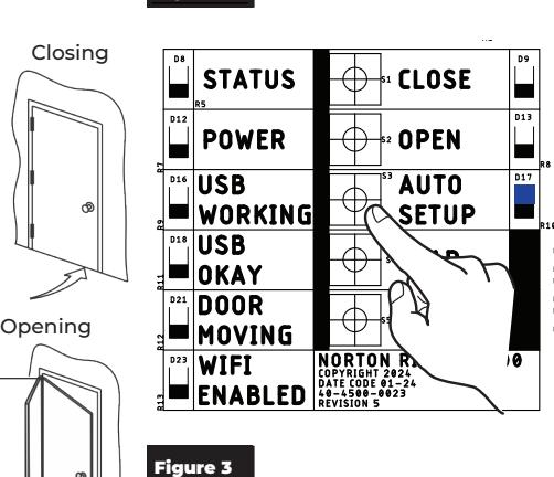
2. Press and release the AUTO SETUP button on the control board.
- ‒ The door will open and close in small increments three (3) times. Allow door to open and close without interference. (Figure 3)
The blue Auto Setup LED will turn off once Auto Setup is complete.
B. Adjust additional settings via WiFi:
Use the WiFi interface to configure additional settings.
NOTES:
- y Some options are available through WiFi programming only.
- y If all LEDs flash after a button press, the input was not accepted. Refer to the Log information on the WiFi Support Page for details. (See page 21)

Speed/Force and Timing/Location settings must be adjusted to meet ANSI BHMA A156.19 (American National Standard for Power Assist and Low Energy Power Operated Doors) requirements for opening and closing based on door weight and width.
Continue with "Connections" on page 7


Operator Setup via WiFi
After the operator has been successfully installed and power has been applied (refer to "Initial Operator Setup" on page 3), follow these steps to program the operator via the WiFi interface.
For definitions of the options on the WiFi interface, refer to Appendix B on page 16.
A. Connect a mobile device to the operator:
1. Turn on the operator WiFi pressing the WiFi button on the bottom of the operator end cap. (Figure 4)
To confirm that WiFi has been turned on:
- y The red WIFI ENABLED LED on the operator's control board will indicate that WiFi has been successfully turned on. (This will only be visible if the operator cover has been removed.) (Figure 5)
- y The operator SSID will be displayed in the smart device's list of available WiFi connections.
NOTES:
- ‒ WiFi automatically turns off after 20 minutes of inactivity.
- ‒ For additional security, WiFi can be turned off immediately by pressing the WiFi button again.
- ‒ The operator serial number and IP address are located on under the cover locking bracket on the bottom end cap. (Figure 4)
- 2. Connect to the 4500 operator's network.
To connect using a Smart Device's camera:
- ‒ Open the camera application on the smart device.
- ‒ Scan (1) Serial Number QR code and (2) IP address QR code (Figure 4)
To manually connect:
- ‒ Open the WiFi or Networks application on the smart device and find the associated operator network (beginning with NR_4500_, followed by the operator's SSID). (Figure 6)
- ‒ Once found, connect to the network. (Figure 7)
-
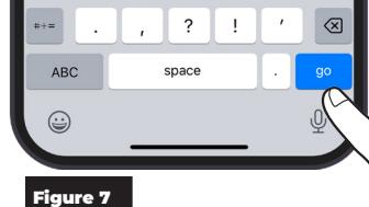
3. On the smart device's web browser, enter http://192.168.4.1 into address bar. (Figure 7)
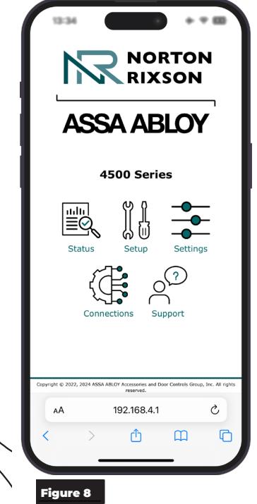
- ‒ The 4500 Series Operator home page will be displayed when connection has been successfully established. (Figure 8)
On the Operator home page, icons are available for quick access to each application page.

NOTES:
- y If the smart device is connected through a VPN service, the VPN must be disabled for web pages to load correctly.
- y Only one device can be connected at a time.
- y Only open one tab at a time.
- y Depending on the device settings, it may be necessary to turn on "Airplane Mode" and then connect to the WiFi.
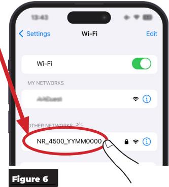
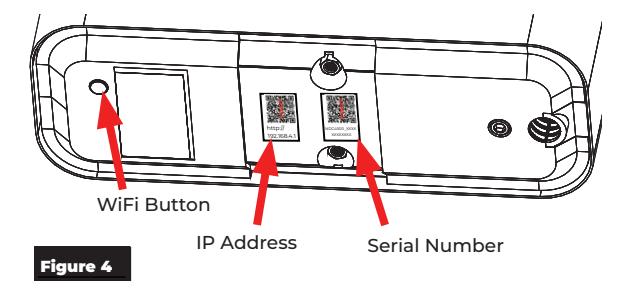
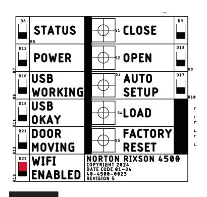
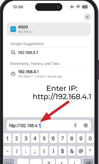
Figure 5

Operator Setup via WiFi (cont.):
B. Set door open and closed positions.
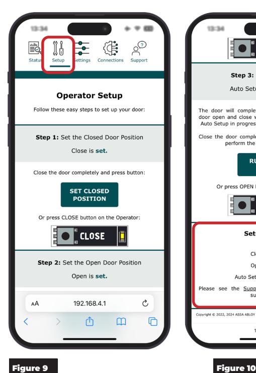
To set the door open and closed positions for the operator, select the Setup application page (Figure 9) and perform the following steps.
- 1. Manually close the door and select "Set Closed Position". (Figure 9)
- 2. Open the door to the fully open position (Limited to 90°). Holding the door open, select "Set Open Position". (Figure 9)
NOTE: If there is a wall or door stop at the fully open position, hold the door slightly away from wall or stop.
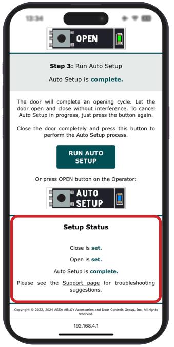
3. Close the door completely and select "Auto Setup" to perform the Auto Setup Process. (Figure 10)
NOTE: The door will automatically move through an opening cycle. Be sure there is no obstruction.
Once done, the Setup Status located on the bottom of the screen will show that each step has been completed. (Figure 10)

Operator Setup via WiFi (cont.):
C. Adjust the Operator Settings.
Speed/Force & Timing/Location Settings
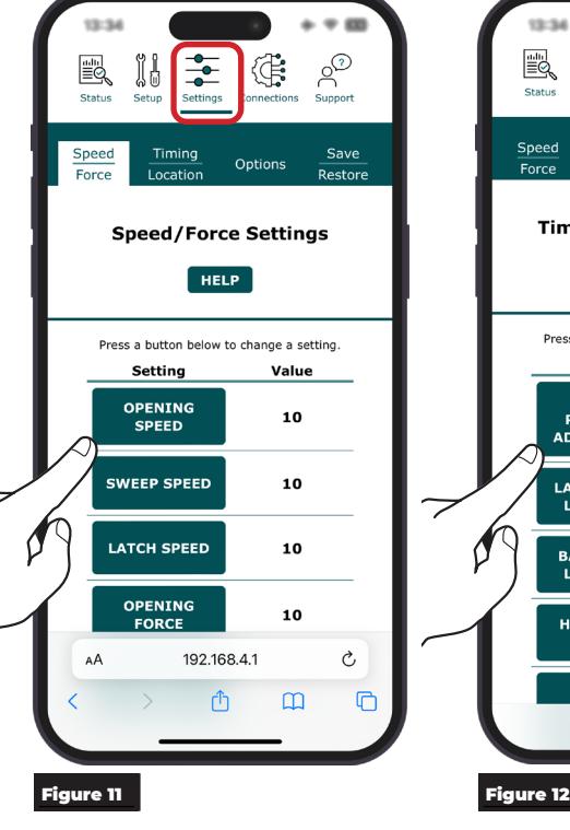
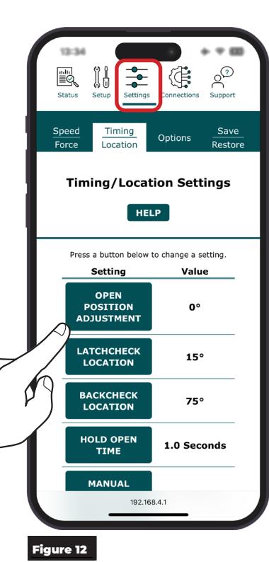
Speed/Force Settings (Figure 11) and Timing/ Location Settings (Figure 12) are automatically adjusted to meet BHMA requirements when AutoSetup is completed.
If the settings need to be adjusted manually, select each option and choose the setting or adjust slider to the desired value.

Speed/Force and Timing/Location settings must be adjusted to meet ANSI BHMA A159.19 (American National Standard for Power Assist and Low Energy Power Operated Doors) requirements for opening and closing based on door weight and width.
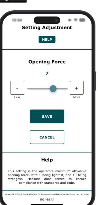
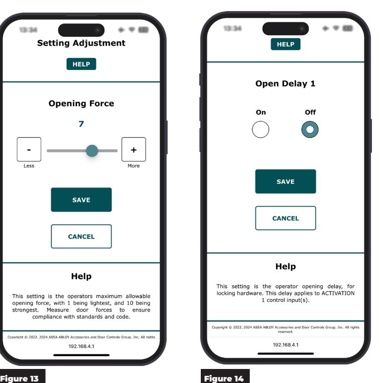
- ‒ For options that have a value range , a slider will be displayed allowing the desired range to be selected, as shown in Figure 13.
- ‒ For options that have a selectable setting , such as On or Off, buttons will be displayed, as shown in Figure 14.
Click on the setting to adjust the value. After an adjustment has been made, click Save to set the value or Cancel to revert to the operator's current setting.
Continue with "Connections" on page 7

Connections
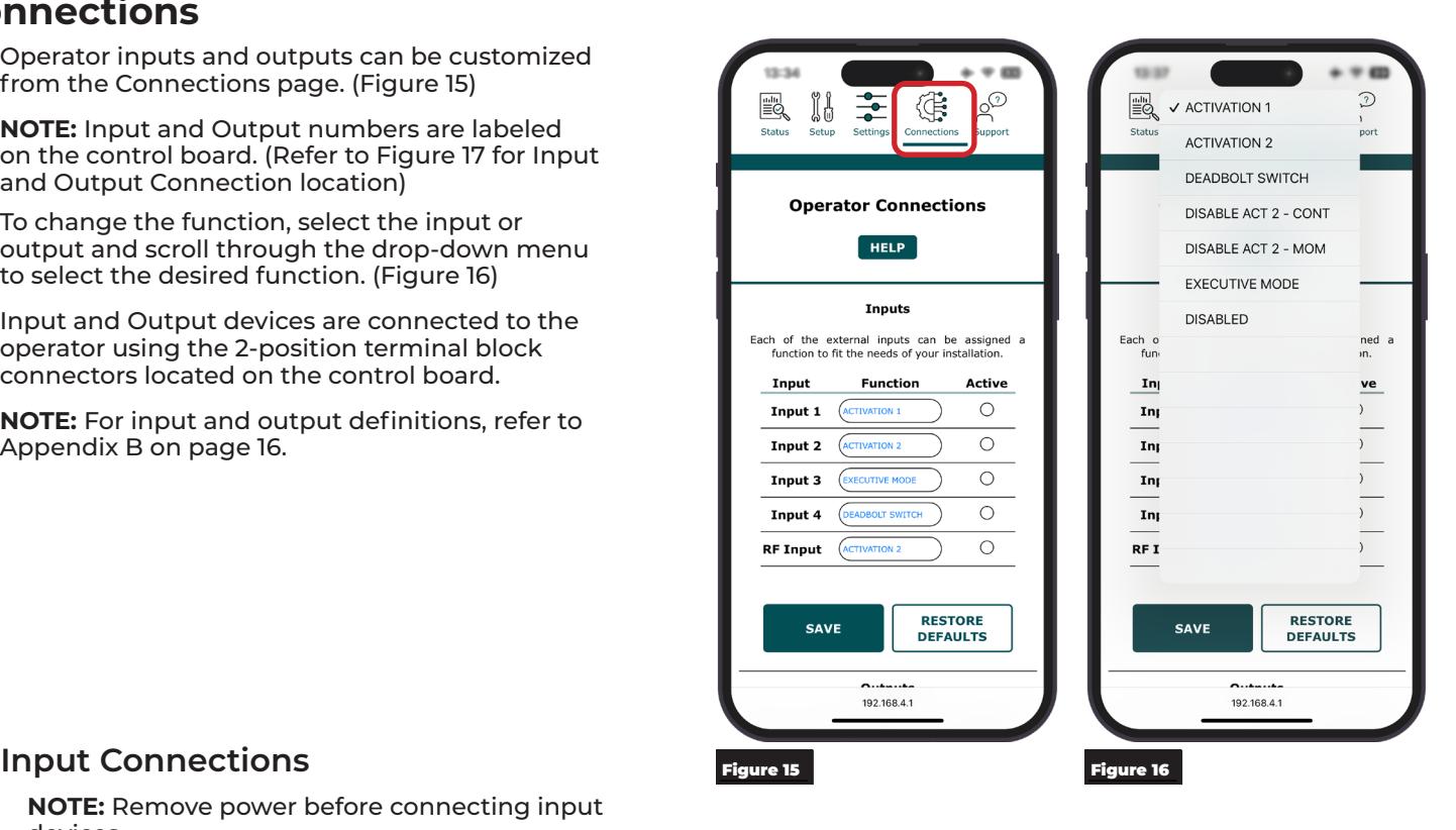
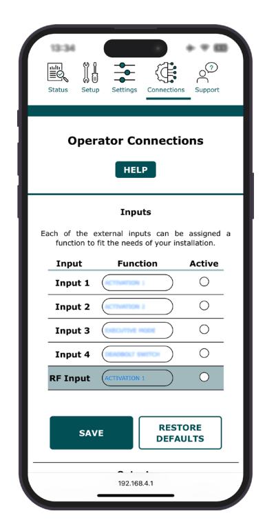
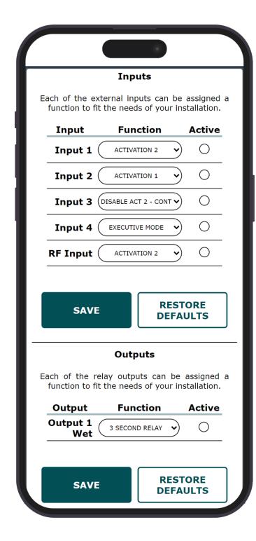
Operator inputs and outputs can be customized from the Connections page. (Figure 15)
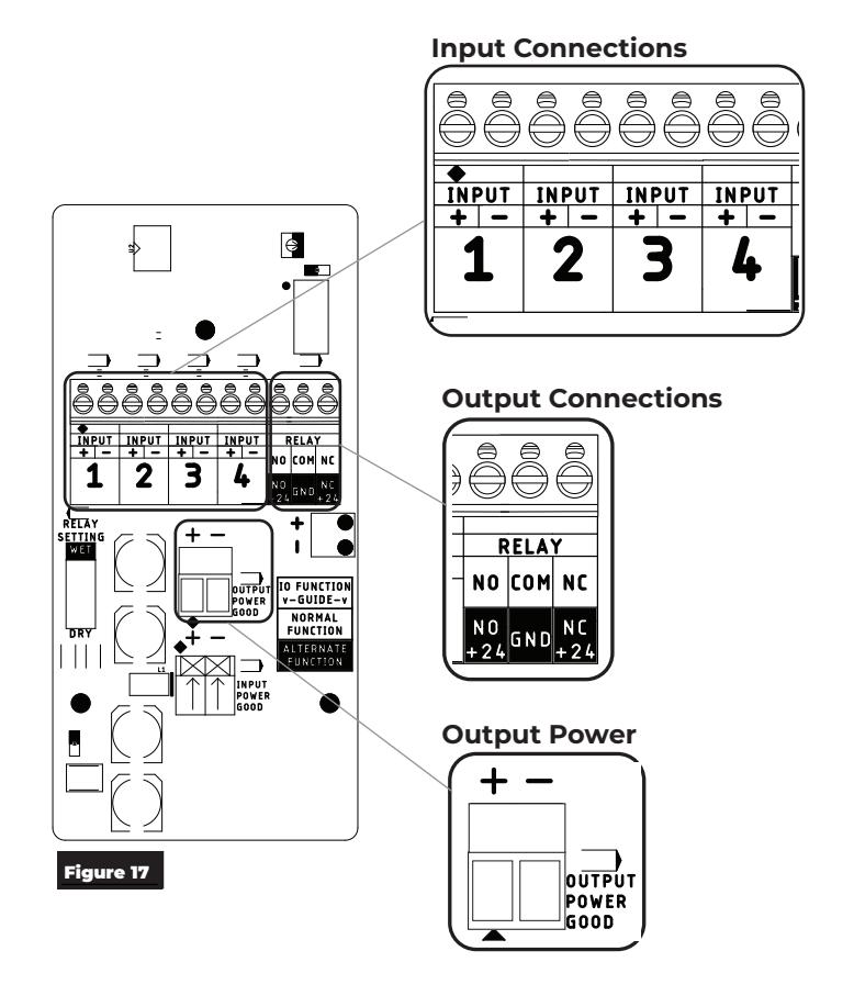
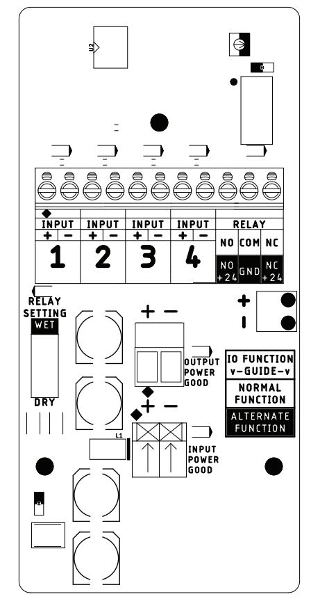
NOTE: Input and Output numbers are labeled on the control board. (Refer to Figure 17 for Input and Output Connection location)
To change the function, select the input or output and scroll through the drop-down menu to select the desired function. (Figure 16)
Input and Output devices are connected to the operator using the 2-position terminal block connectors located on the control board.
NOTE: For input and output definitions, refer to Appendix B on page 16.
NOTE: Remove power before connecting input devices.
Use the 2-position terminal block connectors labeled INPUT on the control board to add input devices on any of the four (4) inputs connections. (Figure 17)
The input terminals are dry contact inputs: ‒ one terminal (+) for the signal from the input device
‒ one terminal (-) for the common.
Output Connections
Use the terminal block connections on the control board labeled Relay or Output Power to add any necessary outputs, such as electric strikes. (Figure 17)
NOTE: Relay outputs can be customized.
Relay 1 : Form C relay with Normally Open and Normally Closed contacts.
An open event will activate the contacts for 3 seconds, then deactivate.
Combine Relay 1 with a Wet/Dry switch to use it as a dry contact or 24V 250mA output.
Output Power : Accessory 24V 200mA constant power.

RF Input
NOTE: RF Receivers are pre-paired with included activation switches at the factory.
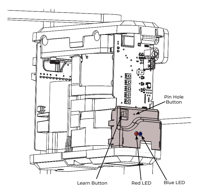
To program an RF input :
-
1. Press and release the learn button.
- ‒ The red LED will light.
-
2. Press the button on the transmitter.
- ‒ The blue LED will illuminate when learned.
NOTE: When an activation signal is received, the blue LED will light.
Signal Strength Indicator :
Press and hold a transmitter button for 3 seconds. The signal strength indicator LED is activated.
Green = Strong Signal Yellow = Medium Signal Red = Weak Signal
To forget a single RF transmitter :
- 1. Press the learn button and pin hole button until red LED flashes once (~2 seconds).
- 2. Press transmitter twice within 10 seconds.
- 3. Verify the transmitter does not activate an RF input.
To forget ALL transmitters :
- 1. Press learn button and pin hole button until the blue LED lights (~10 seconds).
- 2. Verify that none of the transmitters activate RF Input.

Wiring Diagrams
Example 1: Standard Activation
Hardware Components:
- ‒ One (1) 4500 Series Low Energy Operator
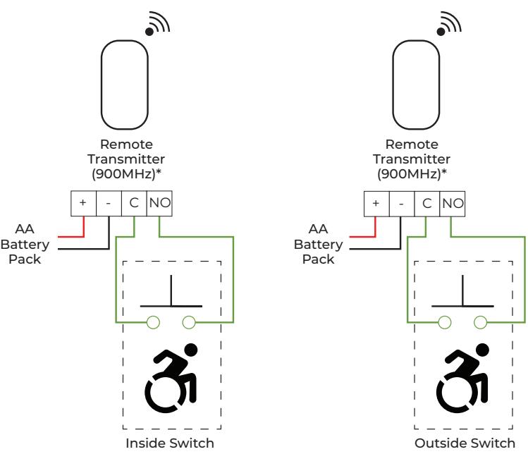
- ‒ Two (2) Activation switches*
Description of Operation:
- ‒ Door normally closed.
- ‒ Inside/Outside door switch activates operator.
- ‒ In case of power loss, operator is inactive.
Input Configuration:
*Factory pre-paired with integrated RF receiver on 4540xSQPB, 4540xWTO models.

Wiring Diagrams (cont.)
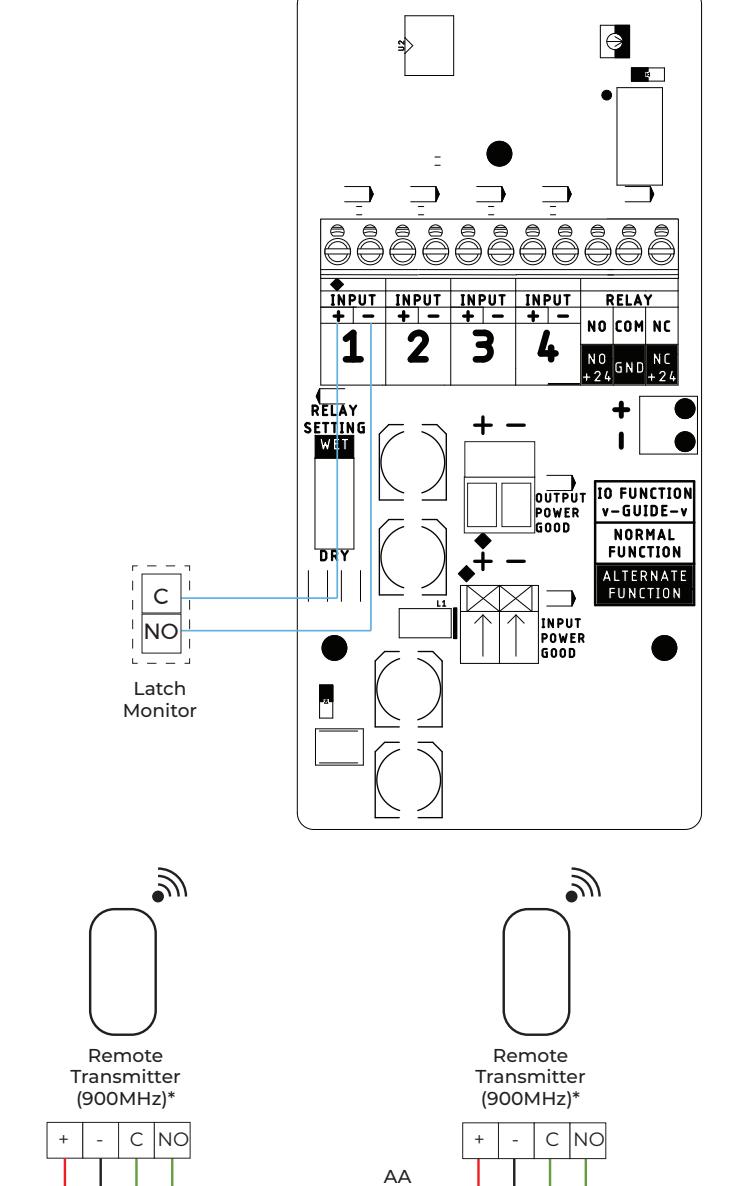
Example 2: Push/Pull with Deadbolt
Hardware Components:
- ‒ One (1) Deadbolt
- ‒ One (1) Latch Monitor
- ‒ One (1) 4500 Series Low Energy Operator
- ‒ Two (2) Activation switches*
Description of Operation:
- ‒ Door normally closed.
- ‒ Inside/Outside door switch activates operator.
- ‒ Projecting deadbolt disables activation switches.
- ‒ Retracting deadbolt re-enables activation switches.
- ‒ In case of power loss, operator is inactive.
Input Configuration:
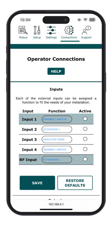
Battery Pack
Inside Switch Outside Switch
*Factory pre-paired with integrated RF receiver on 4540xSQPB, 4540xWTO models
AA Battery Pack

Wiring Diagrams (cont.)
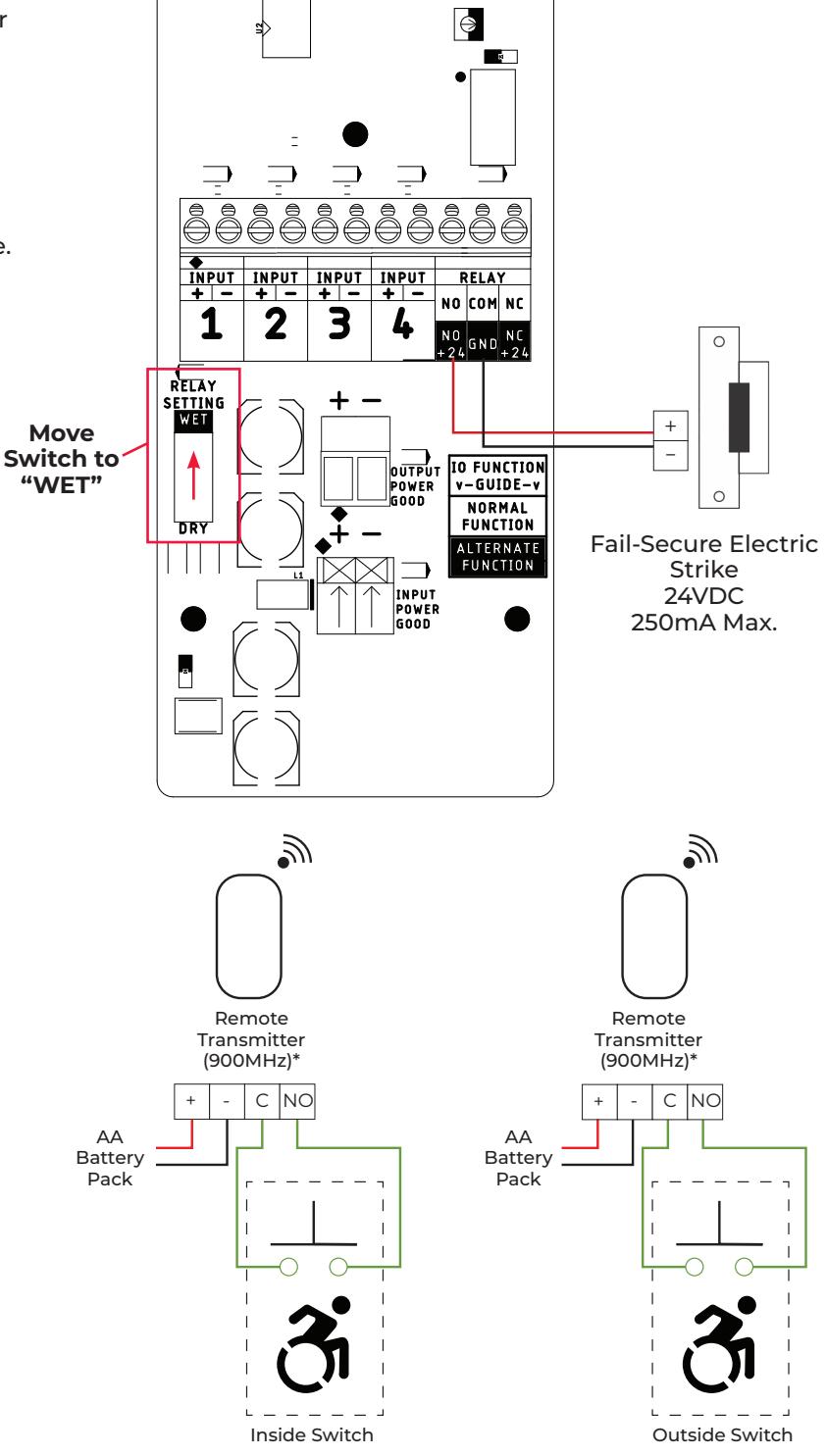
Example 3: Fail Secure Electric Strike
Hardware Components:
- ‒ One (1) 4500 Series Low Energy Operator
- ‒ Two (2) Activation switches*
- ‒ One (1) Electric Strike
Description of Operation:
- ‒ Door normally closed.
- ‒ Inside/Outside door switch activates operator.
- ‒ In case of power loss, operator is inactive.
- ‒ Electric strike is Fail-Secure (Locked when power is removed. Power is applied to unlock door.)
Input/Output Configuration:
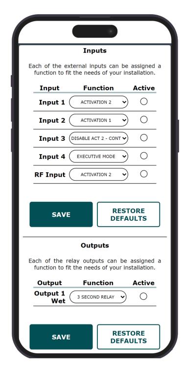
*Factory pre-paired with integrated RF receiver on 4540xSQPB, 4540xWTO models.

Wiring Diagrams (cont.)
Example 4: Fail Safe Electric Strike
Hardware Components:
- One (1) 4500 Series Low Energy Operator
- Two (2) Activation switches*
- One (1) Electric Strike
Description of Operation:
- Door normally closed.
- Inside/Outside door switch activates operator.
- In case of power loss, operator is inactive.
- Electric strike is Fail-Safe (Unlocked when power is removed. Power is applied to lock the door.)
Input/Output Configuration:
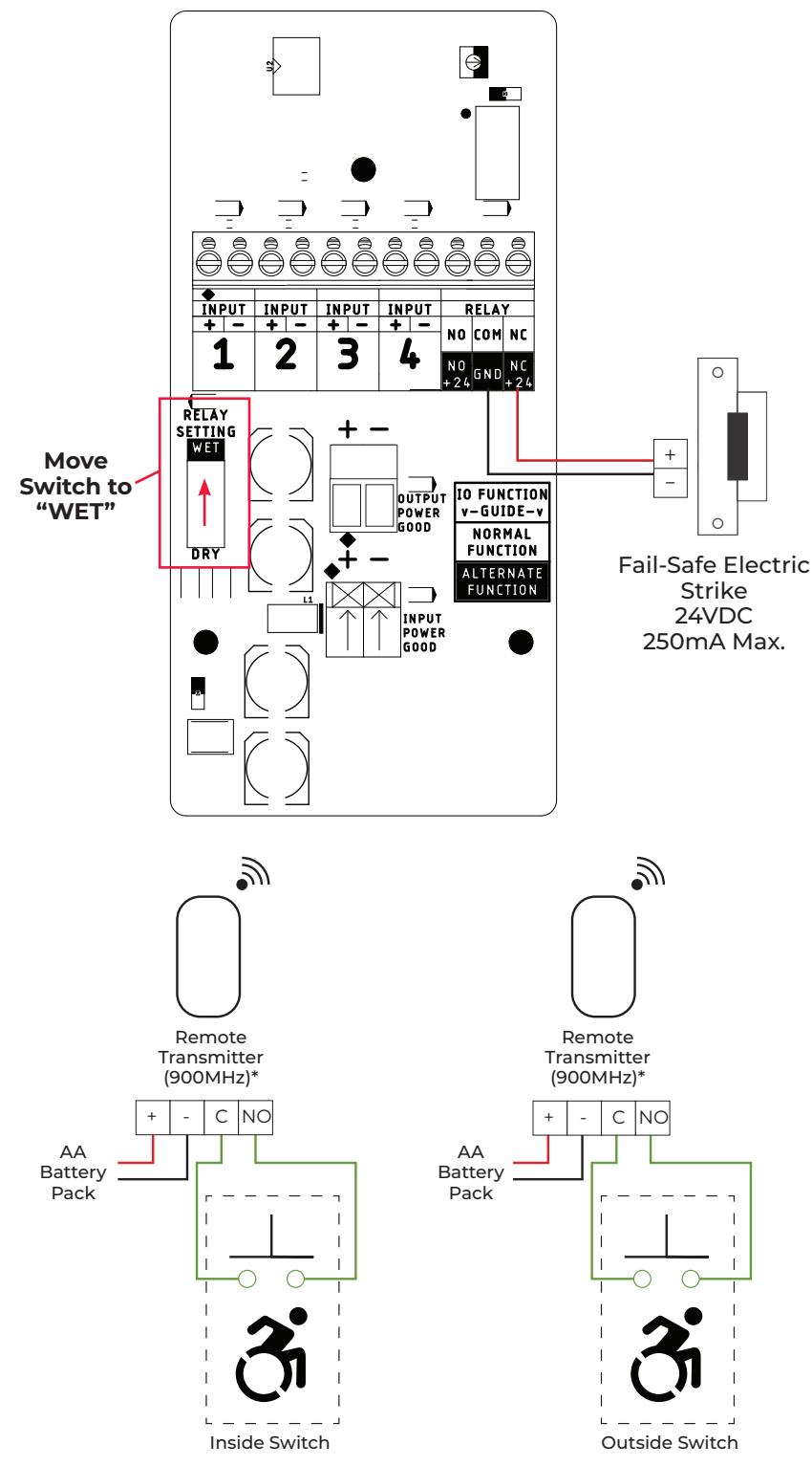
*Factory pre-paired with integrated RF receiver on 4540xSQPB, 4540xWTO models.
80-9345-0003-020 Rev 3 01/25

Troubleshooting and Support
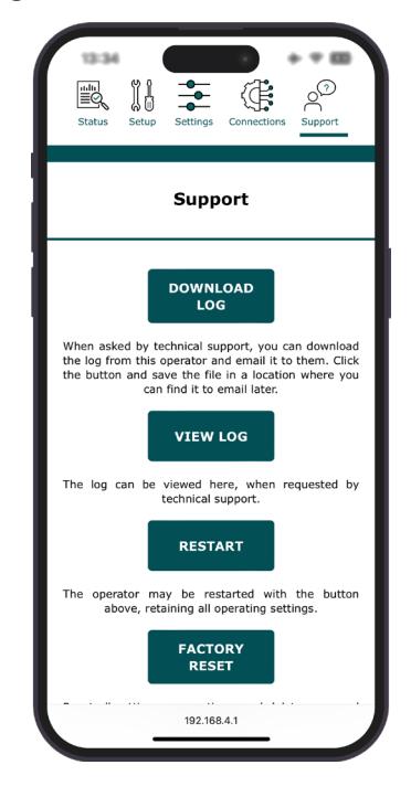
The support page provides information to assist in troubleshooting the 4500 Series operator.
Refer to "Support Page" on page 21 for additional information.
If additional assistance is needed beyond the information provided on this application page, contact Technical Support.
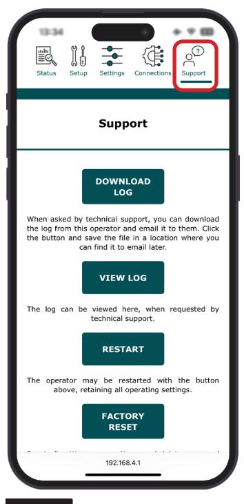
Figure 18
Appendix A: Physical Interface
Control Board
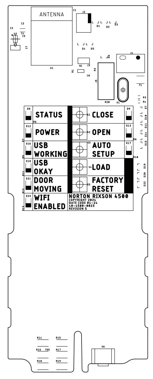
The following information defines the function buttons and LEDs on the Control Board of the 4500 Operator.
STATUS (LED) :
White LED blinks at a steady state during normal operation.
POWER (LED) :
Red LED is solid during normal operation. Blinking light indicates a fault is present, see WiFi for fault description.
USB WORKING (LED) :
Only used during firmware updating. Yellow LED blinks when USB drive is reading or writing.
USB OKAY (LED) :
Only used during firmware updating. Yellow LED is solid when a firmware file is found on USB. LED goes out when firmware update is complete.
DOOR MOVING (LED) :
Yellow LED Blinks when door movement is detected.
WIFI ENABLED (LED) :
Red LED blinks when the Wifi is enabled and solid once a device is connected.
CLOSE (LED) :
Yellow LED blinks when closed position has not been set, is solid when the door is in the closed position.
CLOSE (BUTTON) :
Sets door Close position to current position.
Pressing again overrides the existing setting with the current door position.
Press and hold Close and Open together to erase open and closed positions.
Function also available on WiFi Interface.
OPEN (LED) :
Green LED blinks after closed position is set and open position has not been set, is solid when the door is in the open position.
OPEN (BUTTON) :
Sets door Open position to current position.
Pressing again overrides the existing setting with the current door position.
Press and hold Close and Open together to erase open and closed positions.
Function also available on Wifi Interface.
AUTO SETUP (LED) :
Blue LED blinks when the Open and Close positions have been set, but Auto Setup has not been ran. Blinks during auto setup.
AUTO SETUP (BUTTON) :
Runs Auto Setup to set initial door speeds. Function also available on Wifi Interface.
LOAD (BUTTON) :
Reserved for future use.
FACTORY RESET (BUTTON) :
Reset all settings, including door position, to factory defaults.
WIFI (BUTTON) : (located on the bottom end cap) Press once to turn on Wifi.
Press and hold for 5 seconds to put door in Hold Open (can be disabled in Settings>Options.)

Appendix A: Physical Interface (cont.)
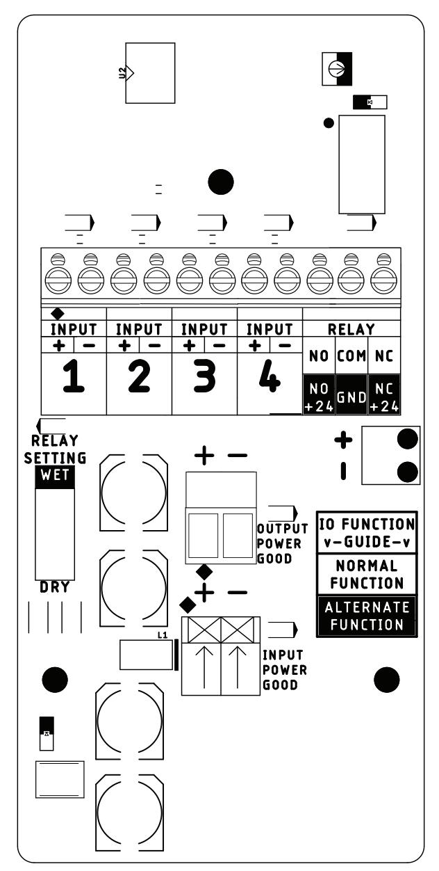
Input/Output (I/O) Board
The following information defines the connections and terminals on the I/O board of the 4500 Operator.
INPUT TERMINALS : Control inputs. Usage is described in "Input Connections" on page 7.
OUTPUT RELAY TERMINALS : Wet (24V 250mA) or dry Form C (SPDT, NO and NC Output). Use is described in "Output Connections" on page 7.
RELAY SETTING : Changes the Output Relay between Wet (24V 250mA) or Dry.
OUTPUT POWER TERMINAL : Continuous 24V 200mA outlet power.
INPUT POWER CONNECTION : Connection for 24V inlet power from wall transformer.
Appendix B: WiFi Interface
Home Page
The following information defines the options available on the Home Page of the WiFi Interface.
STATUS :
Current status of the operator.
SETUP :
Initial setup page (items on this page may also be set using the buttons on the main board.)
SETTINGS :
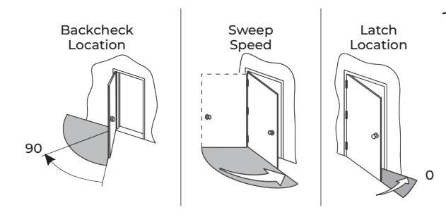
Door Opening and Closing Times, Maximum Forces as well as additional settings can be changed on this page. Speed/Force and Timing/Location settings must be adjusted to meet ANSI BHMA A159.19 (American National Standard for Power Assist and Low Energy Power Operated Doors) requirements for opening
CONNECTIONS :
Operator Functions are assigned to Inputs and Outputs on this page.
and closing based on door weight and width.
SUPPORT :
Operator Logs, restart, reset, and errors. Operator Status Page
Status Page
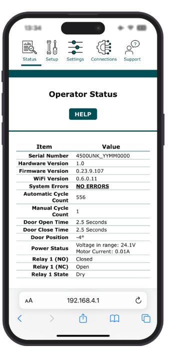
The following defines the information available on the Status Page of the WiFi Interface.
SERIAL NUMBER :
Unique serial number.
HARDWARE VERSION :
Current hardware version.
FIRMWARE VERSION :
Current firmware version.
SYSTEM ERRORS :
Any errors detected by the operator are listed here. These errors are also listed on the Support Page with troubleshooting suggestions.
AUTOMATIC CYCLE COUNT :
Number of automatic door open/close cycles that the operator has performed in its life.
MANUAL CYCLE COUNT :
Number of manual door open/close cycles that the operator has performed in its life.
DOOR OPEN TIME :
The time it took the door to move from fully closed to fully open position on the last completed automatic open cycle, not including any programmed opening delay.
DOOR CLOSE TIME :
The time it took the door to move from fully open to fully closed position on the last completed automatic open cycle, not including any programmed opening delay.
DOOR POSITION :
The current angular position in degrees, with the closed position being zero degrees.
POWER STATUS :
Input Voltage of the operator and the motor current.
RELAY 1 (NO) :
Current state of Relay 1's normally open contact.
RELAY 1 (NC) :
Current state of Relay 1's normally closed contact.
RELAY 1 STATE :
Wet or Dry.

Appendix B: WiFi Interface (cont.)
Operator Setup Page
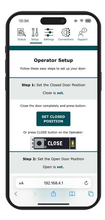
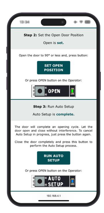
The following information defines the options available on the Operator Setup Page of the WiFi Interface.
SET CLOSED POSITION :
Set or reset door Closed Position. Function also available with physical button. (See User Interface)
SET OPEN POSITION :
Set or reset door Open Position. Function also available with physical button. (See User Interface)
RUN AUTO SETUP :
Runs Auto Setup to set initial door times and max forces. Function also available with physical button. (See User Interface)

Appendix B: WiFi Interface (cont.)
Settings Page
The following information defines the options available on the Settings page of the WiFi Interface.
Speed/Force Tab: The following information defines the options available on the Speed/Force Tab on the Settings Page of the WiFi Interface.
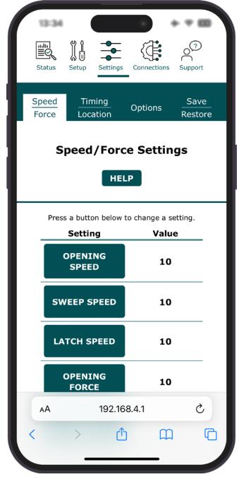
OPENING SPEED :
The speed of door opening. Set door speed to ensure compliance with standards and code.
SWEEP SPEED :
The speed of door in the sweep area. Set door speed to ensure compliance with standards and code.
LATCH SPEED :
The speed of door in the latch area. Set door speed to ensure compliance with standards and code.
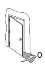
OPENING FORCE :
The operator's maximum allowable opening force. Measure door forces to ensure compliance with standards and code.
CLOSING FORCE :
The operator's maximum allowable closing force. Measure door forces to ensure compliance with standards and code.
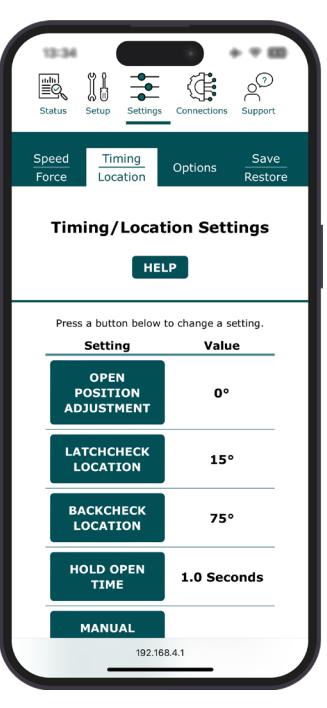
Timing/Location Tab: The following information defines the options available on the Time/Location Tab on the Settings Page of the WiFi Interface:
OPEN POSITION ADJUSTMENT :
This setting is a modifier to the open door position for a door that has been set up.
LATCHCHECK LOCATION :
Door position of the start of the Latch location.
BACKCHECK LOCATION :
Door position of the start of the Backcheck location.
HOLD OPEN TIME :
The amount of time a door will stay in the open position after an activation.
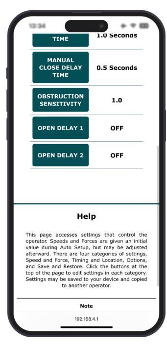
MANUAL CLOSE DELAY :
The amount of time a door will delay before closing after being manually operated.
OBSTRUCTION SENSITIVITY :
Controls obstruction detection. A lower number is less sensitive to obstructions, and a higher number is more sensitive.
OPEN DELAY 1 :
This setting is the operator opening delay. This delay applies to ACTIVATION 1 control input(s).
OPEN DELAY 2 :
This setting is the operator opening delay. This delay applies to ACTIVATION 2 control input(s).

Appendix B: WiFi Interface (cont.)
Settings Page (cont.)
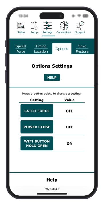
Options Tab: The following information defines the options available on the Options Tab on the Settings Page of the WiFi Interface:
LATCH FORCE :
When ON, a selectable force is applied to the door to hold it against the frame stop.
POWER CLOSE :
When ON, the maximum closing force is increased by an adjustable amount in a user-defined range. Measure door forces to ensure compliance with standards and code.
WIFI BUTTON HOLD OPEN :
By default, holding the WiFi button for five seconds puts door into hold open.
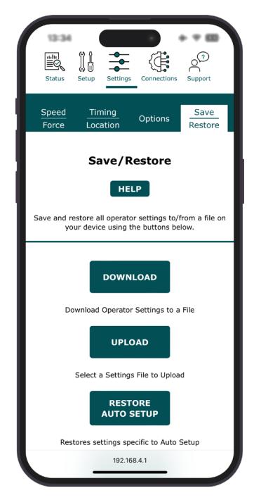
Save/Restore: The following information defines the options available on the Options Tab on the Settings Page of the WiFi Interface.
DOWNLOAD OPERATOR SETTINGS TO A FILE :
Download a file containing all current operator settings.
SELECT A SETTINGS FILE TO UPLOAD :
Replace all current operator settings with settings previously saved.
RESET ALL SETTINGS TO AUTOSETUP :
Reset door Speeds and Maximum forces to those determined during AUTOSETUP. Set door speed to ensure compliance with standards and codes.

Appendix B: WiFi Interface (cont.)
Connections Page
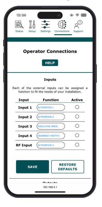
The following information defines the options available on the Connections Page of the WiFi Interface application:
Input Functions: Any Input Function can be applied to any Input.
ACTIVATION 1 :
A momentary closed contact on this input cycles door through an automatic open/close cycle. Tied to Open Delay 1.
ACTIVATION 2 :
A momentary closed contact on this input cycles door through an automatic open/close cycle. Tied to Open Delay 2.
DISABLE ACTIVATION 2 – MOMENTARY :
A momentary closed contact on this input enables/ disables ACTIVATION 2.
While ACTIVATION 2 is disabled DISABLE ACTIVATION 2 RELAY is engaged.
DISABLE ACTIVATION 2 – CONTINUOUS :
A continuous closed contact on this input disables ACTIVATION 2.
While ACTIVATION 2 is disabled DISABLE ACTIVATION 2 RELAY is engaged.
DEADBOLT SWITCH :
A continuous closed contact on this input disables ACTIVATION 1 and ACTIVATION 2.
While ACTIVATION 2 is disabled DISABLE ACTIVATION 2 RELAY is engaged.
When the contact is re-opened ACTIVATION 1 is reenabled and LOCK RELAY is disabled.
Once the door begins moving in the Open position ACTIVATION 2 is re-enabled.
EXECUTIVE MODE :
A momentary closed contact on this input enables/ disables EXECUTIVE HOLD OPEN.
EXECUTIVE HOLD OPEN completes an automatic open and then holds the door at open until either toggled off or the door is manually moved in closing direction.
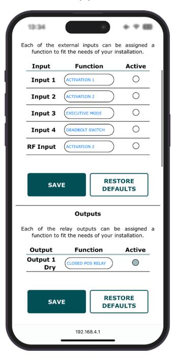
Output Functions: Output Functions can be wired to NO or NC and can be wet or dry.
3 SECOND RELAY :
Relay that switches for 3 seconds + any OPEN DELAY after an activation input is received.
CLOSED POSITION RELAY :
Relay that switches when the door comes to a closed position.
DISABLE ACTIVATION 2 RELAY :
Relay switches with DISABLE ACTIVATION 2 Inputs.

Appendix B: WiFi Interface (cont.)
Support Page
The following information defines the options available on the Support Page of the WiFi Interface:
DOWNLOAD LOG:
Download the current log.
VIEW LOG:
View the current log. Log updates live.
RESTART:
Restart the operator.
FACTORY RESET:
Reset the operator to factory settings. This functions the same as FACTORY RESET button on the operator.
The ASSA ABLOY Group is the global leader in access solutions. Every day we help people feel safe, secure and experience a more open world.

Technical Product Support: Monroe, NC 28112 USA Phone: 877.974.2255 ext: 2 Techsupport.NortonRixson@assaabloy.com