Norton Parallel Rigid Arm Door Closers (PR) & CloserPlus Door Closers (CLP) Installation Instructions
Open the original PDF document
View PDF

Installation Instructions
Parallel Rigid Arm Door Closers (PR) CloserPlus Door Closers (CLP)
Model Numbers Included:
Multi Size Closer PR1601 CLP1601
Sized Closer PR160XBC CLP160XBC
Note: "X" is Sized Closer number designates power size of closer 3 or 4.
ASSA ABLOY
An incorrectly installed or improperly adjusted door closer can cause properly damage or personal injury. These instructions should be followed to avoid the possibility of misapplication or misadjustment.
Additional Closer Options:
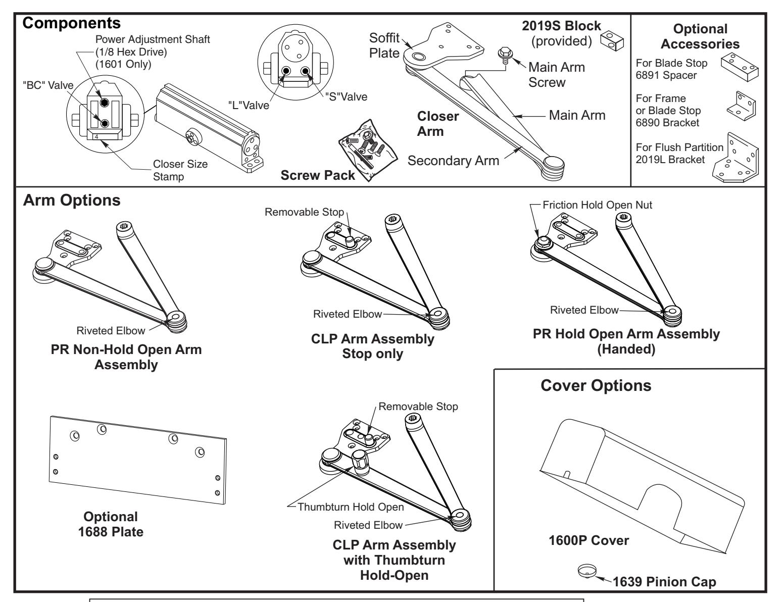
- "H" indicates Hold-Open function for "PR" arms. Arms are handed
- "T" indicates Thumbturn actuated Hold-Open control for "CLP" arms. Optional Accessories:
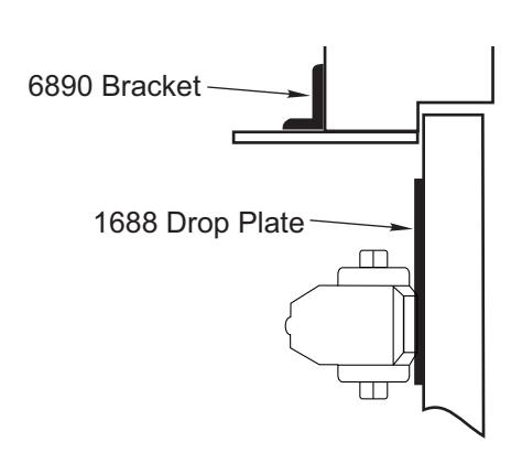
- 1688 Drop plate
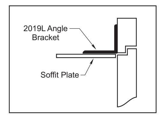
- 2019L, 6890, 6891 Soffit Plate Accessories.
NOTE: For special applications a separate door and frame preparation template is packed with these instructions. In those cases, use this instruction sheet for installation sequence and closer adjustments only.
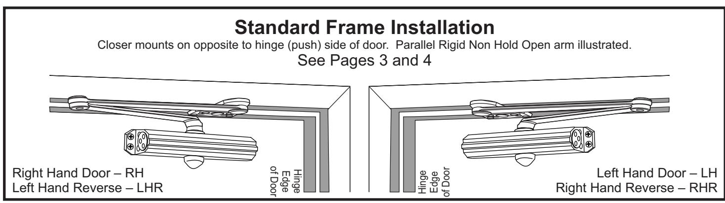
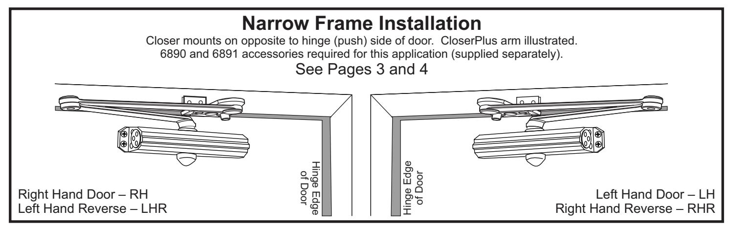
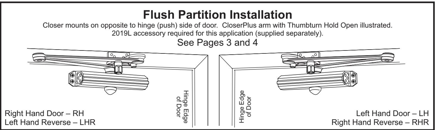

ASSA ABLOY
| Preparation for Fasteners | |||||||||
|---|---|---|---|---|---|---|---|---|---|
| Fasteners | Door or Frame | Drill-Sizes | |||||||
| Standard | Solf Drilling Sorow | Aluminum or Metal | No drill required | ||||||
| Self-Drilling Screw |
Wood
(see Note) |
3/16" (4.30 mm) | |||||||
| 1/4" - 20 machine screw | Metal |
Drill: #7 (0.201" dia.)
Tap: 1/4" - 20 |
|||||||
| Sleeve nuts and bolts |
Hollow
Metal |
9/32" (7 mm) through;
3/8" (9.5 mm) door face opposite to closer |
|||||||
| Aluminum or Wood | 3/8" (9.5 mm) through | ||||||||
| Optional | Through-bolts and grommet-nuts | All |
9/32" (7 mm);
3/8" (9.5 mm) dia. x 3/8" (9.5 mm) deep on door opposite to closer |
||||||
Installation Instructions

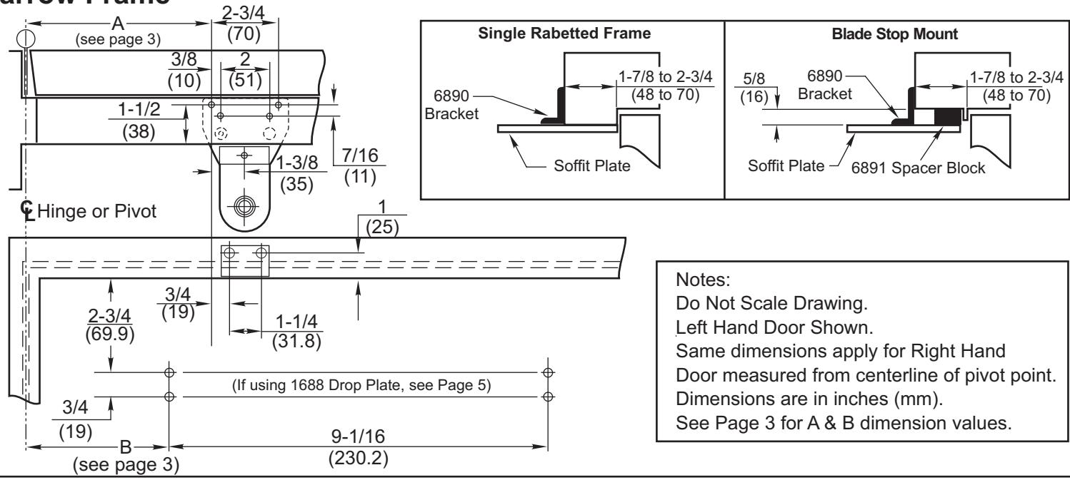
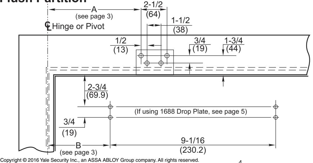
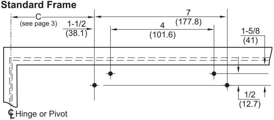
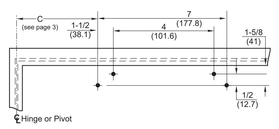
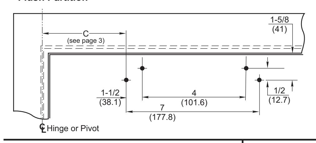
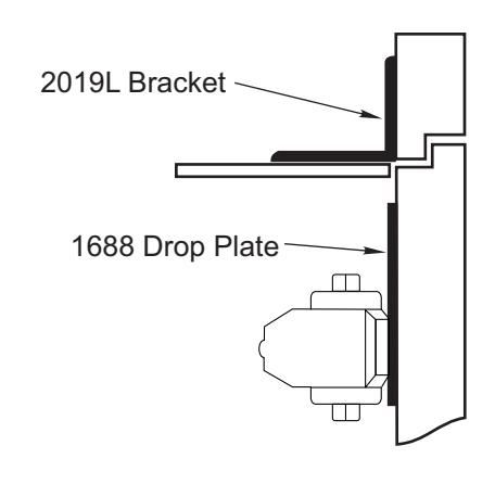
- Select angle of opening and use dimensions shown on Page 4 and Dimension Chart below to locate 4 holes on stop side of door for closer body (or 4 holes on stop side of door for 1688 drop plate, only if required, see Page 5), and 5 holes on stop and/or rabbet for Soffit Plate (or 4 holes on face of transom for 2019L bracket). For applications not covered in these instructions, a separate template will be required.
- Prepare door and frame for fasteners. See "Preparation for Fasteners", Page 2.
- 1601 closers only: Set closer power for door size using Power Adjustment Chart below. Use 1/8" hex wrench supplied to adjust Power Adjustment Shaft ... 18 turns maximum. Turn nut CLOCKWISE to Increase, COUNTER-CLOCKWISE to Decrease power. See Page 6 for the illustration of this step.
- Mount 1688 Drop plate ... only if required (see Page 5).
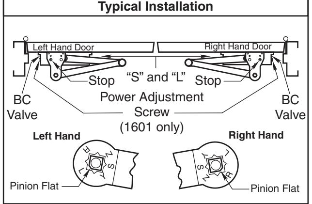
- Install closer with "S" and "L" valves away from hinge edge of door. Note: If using cover, thread in screws before mounting closer. Leave enough gap between the head of the screw and the closer to slide the cover on.
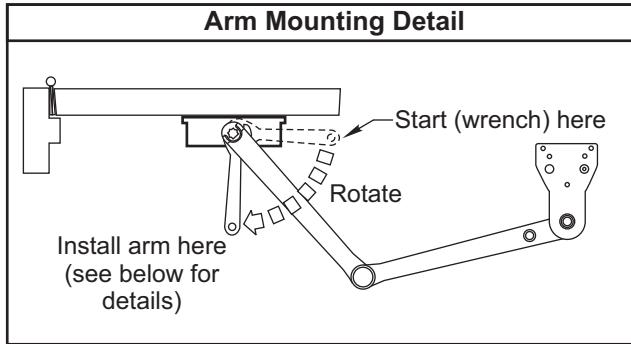
Install Main Arm: Close valves - 'S' and 'L', then turn pinion shaft more than 50° to permit proper alignment of arm mark with pinion flat -
'L' for Left hand door.
'R' for Right hand door.
See "Main Arm Installation Instructions" below.
Make closer adjustments (see page 6) before installing cover ... CAUTION: Do not back valves out of closer completely or a leak will result.
Caution: Closer arm is under spring tension and may be difficult to rotate.
- Reopen valves by turning counter clockwise.
- With door closed, align soffit plate with mounting holes in frame. Fasten soffit plate to frame with oval head screws provided.... use spacer blocks 2019S or 6891, if required.
- If being used, slide the cover over the closer and secure the mounting screws after the closer has been mounted and adjusted.
| Power Adjustment Chart | |||||||||
|---|---|---|---|---|---|---|---|---|---|
|
PARALLEL ARM
INSTALLATION |
* | MAXIMUM DOOR SIZE | |||||||
| DOOR |
34"
(0.85 m) |
36"
(0.9 m) |
40"
(1 m) |
44"
(1.1 m) |
48"
(1.2 m) |
||||
| INT | PR1601/ |
)° TURNS
)WER TMENT |
3 | 5 | 8 | 11 | 14 | ||
| EXT | CLP1601 |
FULL 360
OF PC ADJUS' SHA |
5 | 8 | 11 | 16 | 19 | ||
*30 -360° TURNS MAXIMUM AVAILABLE (Shipped at approximately 8 turns)
| Installation Dimensions Chart | |||||||||||
|---|---|---|---|---|---|---|---|---|---|---|---|
| Dim |
Up to
85° |
85°-
90° |
90°-
95° |
95°-
100° |
100°-
105° |
105°-
110° |
110°-
130° |
130°-
180° |
|||
|
PR1601/
PR160XB |
Standard
and Narrow Frame |
Α |
in.
(mm) |
9-5/8 8-1/8
(244) (206) |
6-1/8
(156) |
||||||
| В |
in.
(mm) |
7-5/8
(194) |
6-1/8
(156) |
4-1/8
(105) |
|||||||
| С |
in.
(mm) |
8-5/8
(219) |
7-1/8
(181) |
5-1/8
(130) |
|||||||
|
C
Flush Partition |
Α |
in.
(mm) |
18) | 1 |
6-1/4
(159) |
||||||
| В |
in.
(mm) |
7-5/8
(194) |
6-1/8
(156) |
4-1/8
(105) |
|||||||
| С |
in.
(mm) |
8-5/8
(219) |
7-1/8
(181) |
5-1/8
(130) |
|||||||
|
CLP1601/
CLP160XI |
Standard and Narrow Frame | Α |
in.
(mm) |
11-1/8
(283) |
10-3/8
(264) |
9-5/8
(244) |
9 (229) |
8-3/8
(213) |
7-3/4
(197) |
||
| В |
in.
(mm) |
9-1/8
(232) |
8-3/8
(213) |
7-5/8
(194) |
7
(178) |
6-3/8
(162) |
5-3/4
(146) |
||||
| С |
in.
(mm) |
10-1/8
(257) |
9-3/8
(238) |
8-5/8
(219) |
8
(203) |
7-3/8
(187) |
6-3/4
(171) |
||||
| Α |
in.
(mm) |
11-1/4
(286) |
10-1/2
(267) |
9-3/4
(248) |
9-1/8
(232) |
8-1/2
(216) |
7-7/8
(200) |
||||
| В |
in.
(mm) |
9-1/8
(232) |
8-3/8
(213) |
7-5/8
(194) |
7
(178) |
6-3/8
(162) |
5-3/4
(146) |
||||
| С |
in.
(mm) |
10-1/8
(257) |
9-3/8
(238) |
8-5/8
(219) |
8
(203) |
7-3/8
(187) |
6-3/4
(171) |
||||
Standard Frame 2-3/4 (70)(see page 3) Wide Stop Frame Narrow Stop Frame 1/2 3/8 (13)(51) 2-3/4 (10)Min. (70)5/8 Min (16)(29)2-1/16 -3/8 (11)(52)(35)Soffit Plate 2019S Block Hinge or Pivot Soffit Plate Blade Stop Frame (see Page 3) 2019S 2-3/4 Block (70)(16)2-3/4 (69.9)
(If using 1688 Drop Plate, see Page 5)
9-1/16
(230.2)

ASSA ABLOY
Narrow Frame
(19)
Soffit Plate
6891
Block
Flush Partition
1688 Drop Plate Mounting Holes
Norton
7 ASSA ABLOY
1688 Drop Plate
Notes:
Left Hand Door Shown. Same dimensions apply for Right Hand Door measured from centerline of pivot point. Dimensions are in inches (mm). See Page 3 for C dimension values.
Narrow Frame
Flush Partition
Thumbturn Hold-Open Feature
The Thumbturn Hold-Open feature is controlled by the knob located on the arm of the unit. Turning this knob clockwise will engage the Hold-Open mechanism and increase the Hold-Open force. Turning this knob counterclockwise will reduce the Hold-Open force and disengage the Hold-Open mechanism. DECREASE - - INCREASE
Thumbturn Action (Units suffixed "T")
Friction Hold-Open Feature Hold door open to opening an
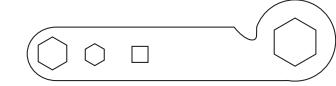
Hold door open to opening angle desired and tighten holderadjustment-nut (wrench supplied) or use 1" Box or Open End wrench.
Unit Adjustment
Closing Power Adjustment-
Using "Power Adjustment Chart" from Page 3, select the correct number of turns for power adjustment shaft that corresponds with the installation. With 1/8" hex-key provided, rotate adjustment shaft full 360° clockwise turns to desired setting. After closer has been installed and proper adjustments made to the sweep and latch, it may be necessary to readjust spring power for good closing action.
Control Valve Adjustments
(See Figure 2.)
Closing Speed Controls (Figure 1 and 2.)
Valve "S" Controls Sweep Range. Valve "L" Controls Latch Range.
Closing Speed Controls Figure 1 CAUTION: DO NOT BACK VALVES OUT OF CLOSER OR A LEAK WILL RESULT. SWEER Standard Closing Cycle Attention: Adjust Closing Speed Time to between 4 to 7 seconds from 90°. Use of the door by handicapped, elderly or small children may require greater closing time. Closing Speed Controls Figure 2. Slow CAUTION: 1/8 DO NOT BACK VALVES OUT OF Hex CLOSER OR A LEAK WILL Key RESULT Fast "L"Valve "S"Valve Closing Power Control Figure 3 See "Power Adjustment Chart" Page 3 Increase Increase 1/8 Hex Key Decrease
Opening Cycle
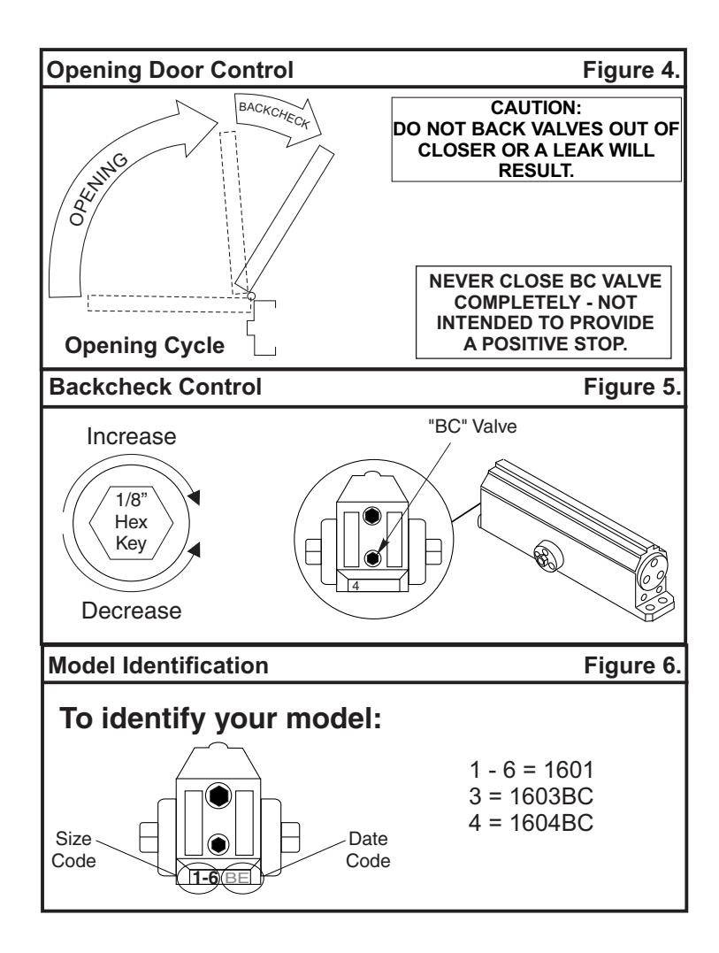
"Backcheck" valve controls the strength of cushioning in Backcheck Range (approximately 70° to maximum swing). NEVER close this valve completely – it is not to provide a positive stop. (see Figure 4 and Figure 5).

Decrease