Norton 9540 Series Door Closer Series 9540 J9540 JL9540 (Regular,Parallel,Top Jamb) Non-Hold Open Installation Instructions
Open the original PDF document
View PDF

ASSA ABLOY
Series 9540 J9540 JL9540 Installation Instructions Multi-Sized 1 to 6 Non-Hold Open
Regular Arm Applications
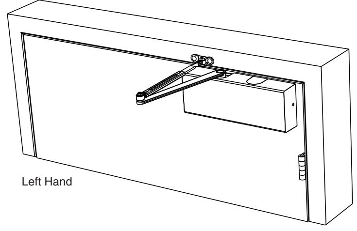
| Regular Arm Application | ||
|---|---|---|
| Contents | Page | |
| Template | 5 | |
| Template with 9854-18 Drop Plate | 6 | |
| Installation Instructions | 7 | |
| Closer Adjustment Instructions | 16 | |
Parallel Arm Applications
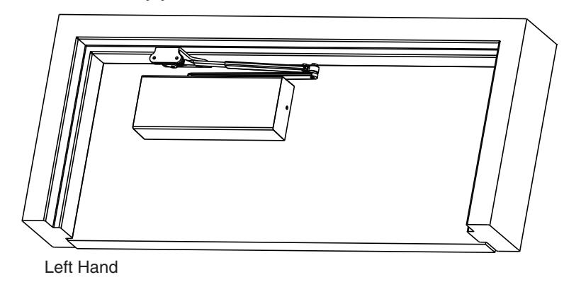
| Parallel Arm Application | |
|---|---|
| Contents | Page |
| Template | 8 |
| Template with 9854-18PA Drop Plate | 9 |
| Installation Instructions Power Adjustment | 10 - 12 |
| Closer Adjustment Instructions | 16 |
Top Jamb Applications
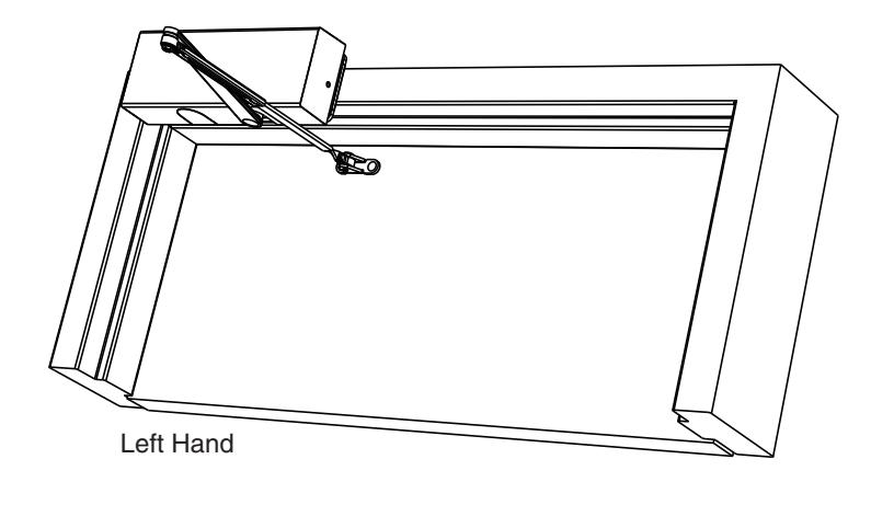
| Top Jamb Arm Application | |||
|---|---|---|---|
| Contents | Page | ||
| Template with 9540-18TJ Drop Plate Use on 1-3/4" Min. Frame Face | 13 | ||
|
Template
Use on 3-1/2" Min. Frame Face |
14 | ||
| Installation Instructions | 15 | ||
| Closer Adjustment Instructions | 16 | ||
9540 ---- 2-9/16" Max. Reveal
J9540 ---- 2-9/16" to 4-13/16" Reveal
JL9540 ---- 4-13/16" to 8" Reveal

IMPORTANT:
- An improperly installed or incorrectly adjusted door closer may cause property damage or personal injury; and will void product warranty.
- To avoid personal injury, DO NOT DISASSEMBLE THIS DOOR CLOSER BODY.
- Door closers must be securely fastened to a properly reinforced door and frame with fasteners provided.
BEFORE INSTALLING:
- The Americans with Disabilities Act (ADA) requires that interior doors, other than fire doors, have an opening force not to exceed 5 lbf as measured 1" from the latch edge of door; force measurement starting 3" from jamb up to 70° of opening These forces do not apply to the force required to retract latch bolts or disengage other devices that hold the door or gate in a closed position.
- The door closer's power size adjustment feature may require adjustment to its lowest setting to comply with ADA opening force guidelines.
- Low opening forces result in lower closing forces which are not always acceptable in closing and latching a door depending on field conditions such as weight of door, hinge conditions, and or stack pressure.
- An auxiliary door stop, by others, is strongly recommended to avoid damage to the door closer and adjacent property.
- Doors should be hung on ball bearing or anti-friction hinges/pivots.
- Door closer must not be installed on the exterior side of a door located in an exterior wall of a building.
- ADA compliant closer.
| Size of Door & Door Closer | |||||
|---|---|---|---|---|---|
|
Type
of Installation |
Interior |
Exterior
In-swinging |
Exterior
Out-swinging |
Recommended
Closer Size |
**Max.
Opening Force Ibs/f |
| 2'4" | 1 | 8 | |||
| 3'0" | 2 | 14 | |||
| Regular & | 3'6" | 2'6" | 3'0" | 3 | 16 |
| Top Jamb | 4'0" | 3'0" | 3'6" | 4 | 22 |
| 4'6" | 3'6" | 4'0" | 5 | 24 | |
| 5'0" | 4'0" | 4'6" | 6 | 26 | |
| 2'4" | 1 | 8 | |||
| 2'6" | 2 | 14 | |||
| Parallel | 3'0" | 2'6" | 3 | 16 | |
| Arm | 3'6" | 3'0" | 4 | 22 | |
| 4'0" | 3'6" | 5 | 24 | ||
| 4'6" | 4'0" | 6 | 26 | ||
TO DETERMINE HAND OF YOUR DOOR:
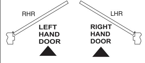

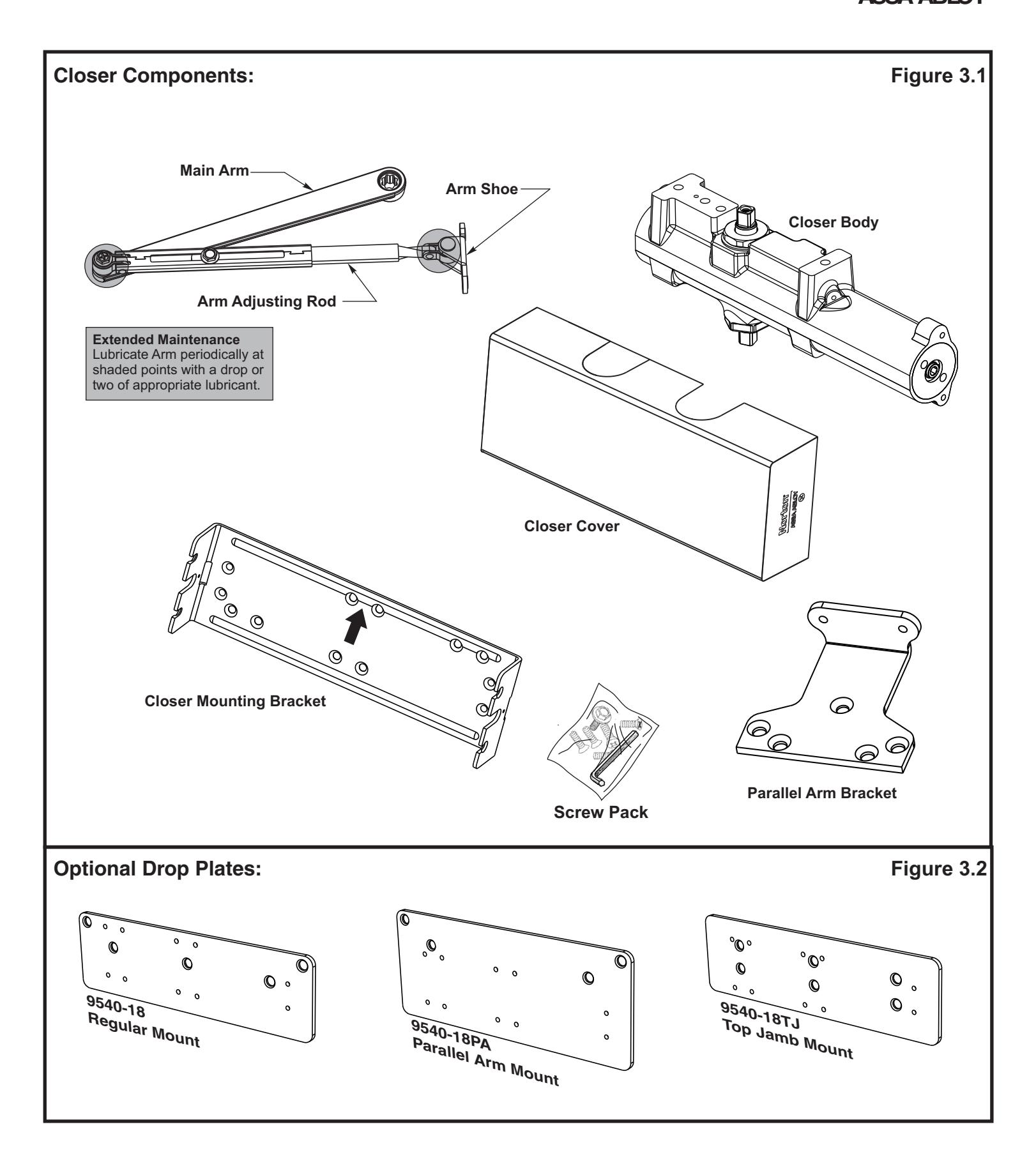

Figure 4.1
|
Figure 4.1
Preparation for Fasteners |
||||
|---|---|---|---|---|
| Fasteners | Drill Size | |||
| #12-14 Self-Drilling Screw |
Aluminum
Metal |
No drill required | ||
| Wood | Drill 1/8" Pilot Hole | |||
| Standard | #12-24 Machine Screw |
Aluminum
or Metal |
Drill #16 (.177" Dia)
Tap #12-24 UNC |
|
| 1/4-20 Machine Screw |
Aluminum
or Metal |
Drill #7 (.201" Dia)
Tap 1/4-20 UNC |
||
| Optional |
Sleeve nuts and bolts
1-3/8" Thick Door - 1-9/32" Length Nut |
Aluminum
or Metal |
9/32" Though
3/8" Through door face opposite of closer mount |
|
| 1-3/4" Thick Door - 1-21/32" Length Nut | Wood | 3/8" Though Door | ||
| Through-bolt and Grommet Nuts | Wood |
9/32" Thought Door
3/8" Dia x 3/8" Deep hole in door face opposite of closer mount |
||
Always consult door/frame manufacturer for fastener compatibility with the material of their door/frame.
- It is recommended that the door, on which the door closer will be installed, be hung on ball bearing hinges. Door must swing freely.
- A separate door stop, supplied by others, is recommended to prevent damage to the door closer, closer arm; or to the door, frame or adjacent walls.
- Door and Frame must be properly reinforced, or use of special fasteners employed, to prevent the mounting screws from pulling out.
- All dimensions are given in inches with corresponding metric dimensions (millimeters) in parentheses.

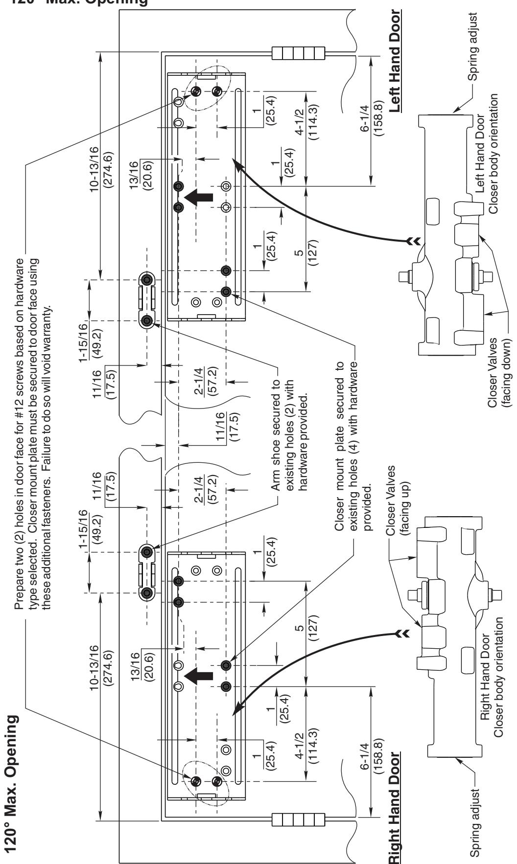
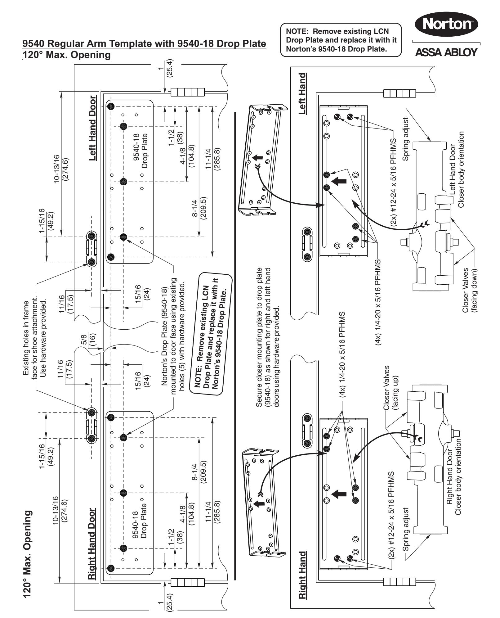
9540 Regular Arm Template 120° Max. Opening
ASSA ABLOY

ASSA ABLOY
Regular Arm Installation Sequence
1. Remove existing LCN arm assembly, closer body and supporting mounting hardware. If existing drop plate is present, replace with Norton drop plate part number 9540-18. See page 3, figure 3.2 of this instruction.
NOTE:The existing LCN drop plate must be replaced with the proper Norton drop plate for the 9540 to perform correctly.
-
2. Inspect existing mounting holes in door and frame for damage. Consult templates listed below to confirm existing holes are located in the proper position:
- Page 5: 9540 Regular Arm Mount
Page 6: 9540 Regular Arm Mount with 9540-18 drop plate.
Improperly templated door or frame may affect door closer performance.
- 3. IMPORTANT: Using template on Page 5, locate and prepare two (2) additional holes for #12 screws for closer mounting plate. Screws will be located under the spring adjust end of closer when installed. See fastener chart page 4. (If installing closer body on Norton's Drop Plate page 6, these additional holes are already present on drop plate)
- 4. Secure drop plate (if required) and/or closer mounting plate to face of door with hardware provided.
Note: See templates on page 5 and 6 for proper orientation of these plates in both Left Hand and Right Hand applications.
5. Fasten the closer body, spring adjust end TOWARD hinge edge of door and valve oriented as stated below to mounting plate with hardware provided (Figure 7.1).
Right hand door:Valves facing UP. Left hand door:Valves facing DOWN.
See templates on page 5 or 6 for illustrations of closer orientation.
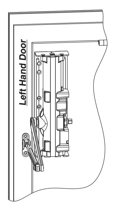
6. Fasten arm shoe of the adjusting rod assembly to frame face with hardware provided. Fasten with pivot point of shoe away from hinge. For additional 15% increase in closing force, position arm shoe with pivot point towards hinge edge of door as shown below. See figure 7.1 below; illustration shows left hand door.
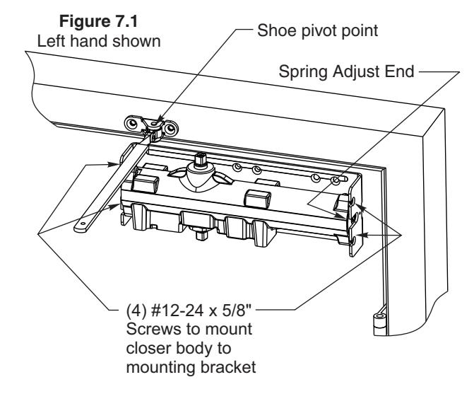
7. Attach main arm to closer pinion as shown below (Figure 7.2) with main arm positioned 90° to door face. Secure to pinion with arm screw provided.
- 8. Pre-load closer unit:
- Ÿ Remove rod screw from adjusting rod. Insert adjusting rod into rectangular tube of main arm assembly (open door slightly if needed).
- Ÿ With door in closed position, rotate main arm until adjusting rod is 90° with respect to door face as shown below (Figure 7.3).
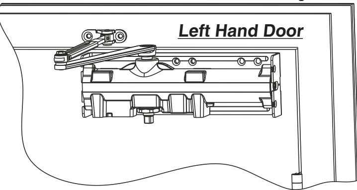
- Ÿ Re-install adjusting rod screw and tighten to maintain closer preload. Reference illustration below (Figure 7.4) for left hand door.
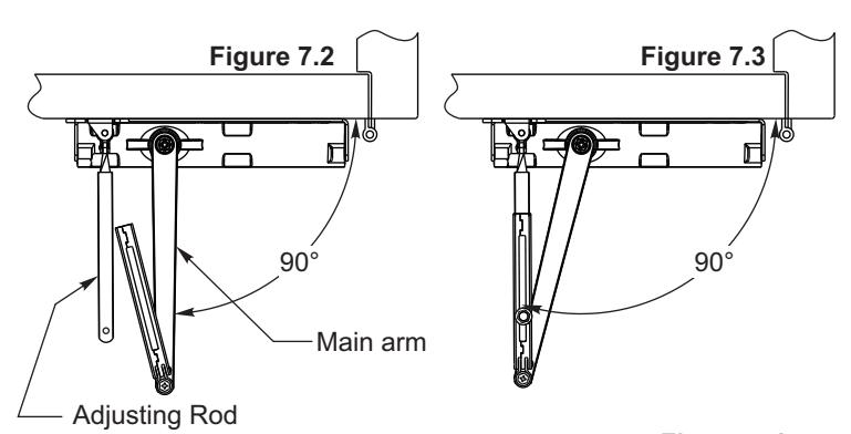
Figure 7.4
-
9. Closer Adjustments: See page 16 for more information.
- A) Adjust closing force using the spring adjust screw. Rotate screw clockwise (CW) to increase force. Rotate screw counter-clockwise (CCW) to decrease closing force. Use hex wrench provided.
- B) Adjust closing speed and latching speed of door using valves identified (Figure 16.1). Rotate valve clockwise (CW) to decrease speed. Rotate valve counter-clockwise (CCW) to increase door
- closing speed. C) Adjust backcheck intensity. Rotate (CW) to increase backcheck intensity. Rotate (CCW) to de-crease backcheck intensity.
- D) Delayed Action : (If equipped) Rotate valve (CW) to increase close delay time. Rotate (CCW) to de-crease close delay time

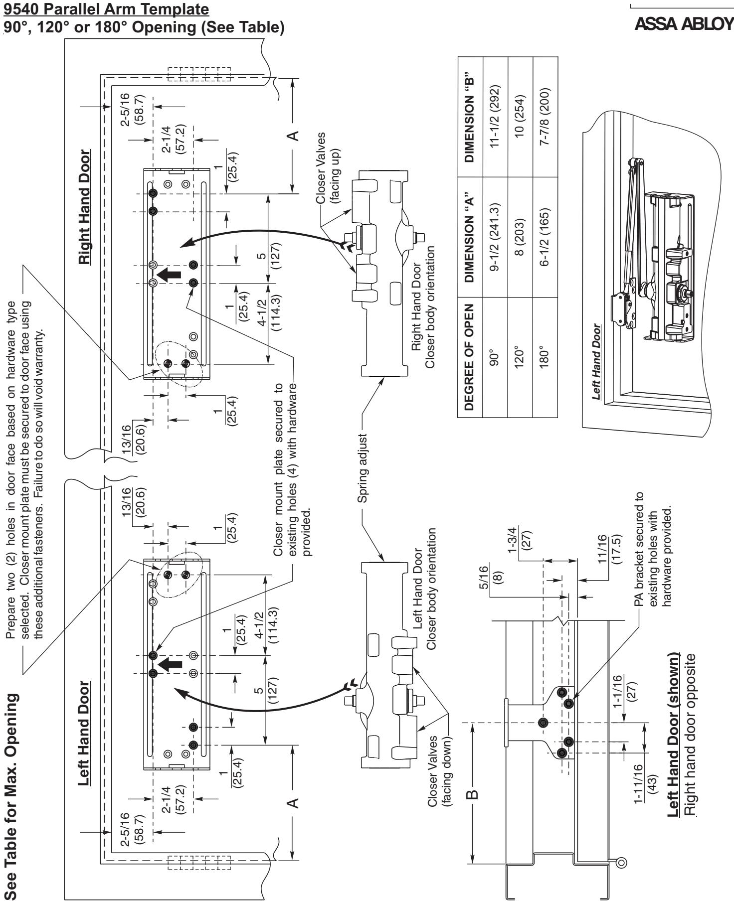

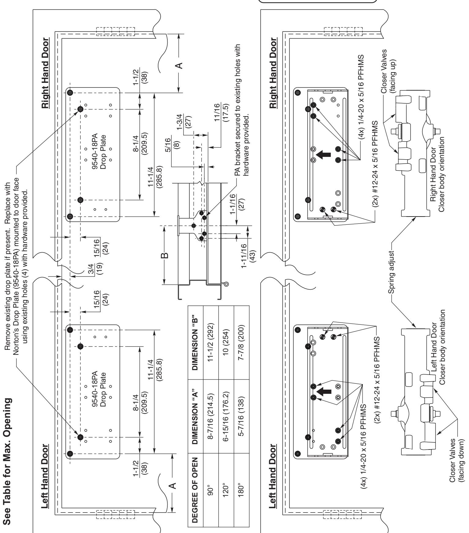
9540 Parallel Arm Template with 9540-18PA Drop Plate 90°, 120° or 180° Opening (See Table)
NOTE: Remove existing LCN Drop Plate and replace it with it Norton's 9540-18PA Drop Plate.
ASSA ABLOY

Parallel Arm Installation Sequence (Page 1 of 3)
- 1. Remove existing LCN arm assembly, closer body and supporting mounting hardware. If existing drop plate is present, replace with Norton drop plate part number 9540-18PA. See page 3, figure 3.2 of this instruction. NOTE:The existing LCN drop plate must be replaced with the proper Norton drop plate for the 9540 to perform correctly.
- 2. Inspect existing mounting holes in door and frame for damage. Consult templates listed below to confirm existing holes are located in the proper position:
Page 8: 9540 Parallel Arm Mount
Page 9: 9540 Parallel Arm Mount with 9540-18PA drop plate.
Improperly templated door or frame may affect door closer performance.
- 3. IMPORTANT: Using template on Page 8, locate and prepare two (2) additional holes for #12 screws for closer mounting plate. Screws will be located under the spring adjust end of closer when installed. See fastener chart page 4. (If installing closer body on Norton's Drop Plate page 9, these additional holes are already present on drop plate)
- 4. Secure drop plate (if required) and/or closer mounting plate to face of door with hardware provided.
Note: See templates on page 8 and 9 for proper orientation of these plates in both Left Hand and Right Hand applications.
5. Fasten the closer body, spring adjust end AWAY from hinge edge of door and valve oriented as stated below to mounting plate with hardware provided.
Right hand door:Valves facing UP. Left hand door:Valves facing DOWN.
See templates on page 8 or 9 for illustrations of closer orientation.
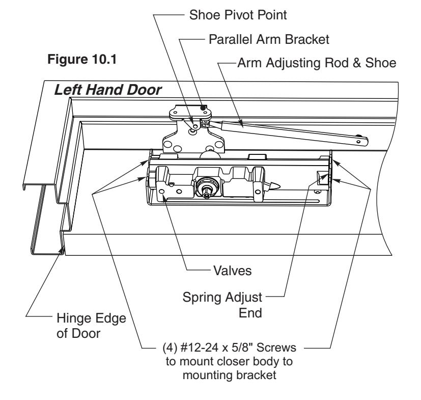
- 6. Fasten the parallel arm bracket to the frame soffit with hardware provided (Figure 10.1).
- 7. Fasten arm shoe of the adjusting rod assembly to the parallel arm bracket with hardware provided. Fasten with pivot point of shoe away from hinge (Figure 10.1).
Installation instructions continued on next page.

Parallel Arm Installation Sequence (Page 2 of 3)
7. Attach main arm to closer :
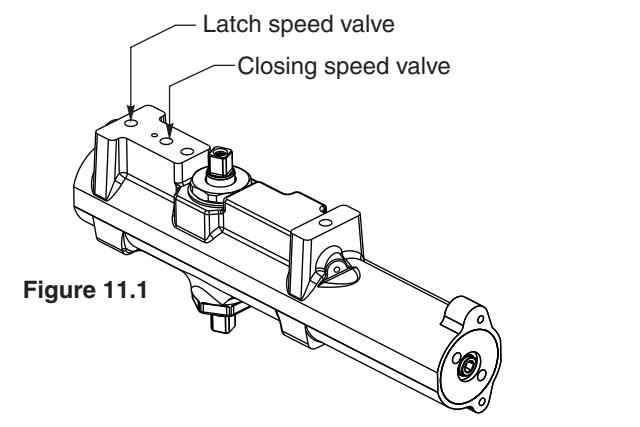
- Using hex wrench provided, turn closing speed and latch speed valves clockwise (CW) until seated (DO NOT OVER TIGHTEN) Figure 11.1
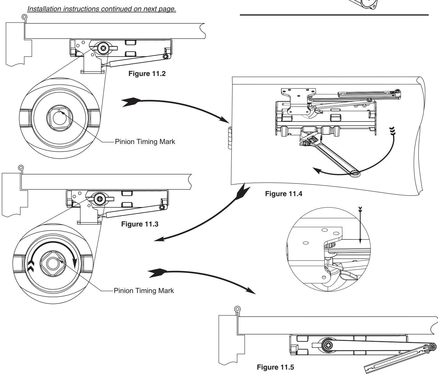
- See Figure 11.2 for Timing Mark. Placing a wrench on under side of pinion, rotate wrench approximately 45° toward hinge edge of door as shown (Figure 11.4) until Timing mark is oriented as shown in Figure 11.3.
- Immediately place arm on pinion (Figure 11.4) so that it is parallel to door face (Figure 11.5); secure in place with arm screw and washer assembly provided.
- Re-open closing speed and latch speed valves (DO NOT REMOVE VALVES FROM CLOSER BODY).
Parallel Arm Installation Sequence (Page 3 of 3)

8. Assemble & Preload Arm:
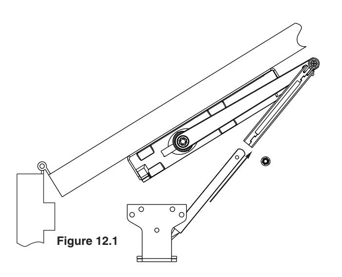
- Remove adjusting rod screw, open door slightly and slide rod into tube of main arm assembly (Figure 12.1).
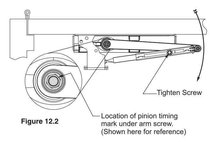
- Close door, re-install adjusting rod screw (Figure 12.2).
- Pull main arm and tube assembly away from door face as shown (Figure 12.2).
- Using 7/16" wrench, tighten adjusting rod screw to secure arm assembly at desire preload setting (Figure 12.2).
9. Power adjustment:
- Loosen adjusting rod screw.
- To increase the power of the closer, re-adjust the arm elbow pivot point nearer the door face (Figure 12.3).
- To decrease power of the closer, re-adjust the arm elbow pivot point farther away from door face (Figure 12.4).
- Re-tighten adjusting rod screw to secure arm setting.
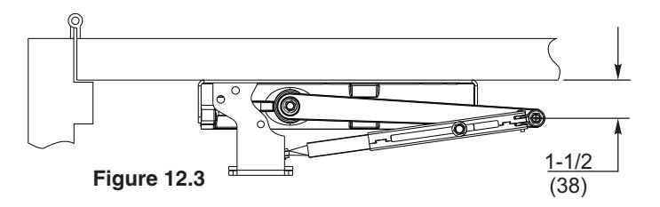
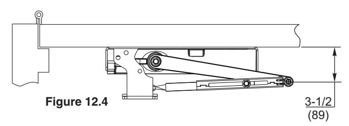
Dimension may have to be increased for some parallel applications requiring ADA opening forces.
-
Tighten Screw 10. Closer Adjustments: See page 16 for more information.
- A) Adjust closing force using the spring adjust screw. Rotate screw clockwise (CW) to increase force. Rotate screw counter-clockwise (CCW) to decrease closing force. Use hex wrench provided.
- B) Adjust closing speed and latching speed of door using valves identified (Figure 16.1). Rotate valve clockwise (CW) to decrease speed. Rotate valve counter-clockwise (CCW) to increase door closing speed.
- C) Adjust backcheck intensity.
Rotate (CW) to increase backcheck intensity. Rotate (CCW) to de-crease backcheck intensity.
D) Delayed Action : (If equipped) Rotate valve (CW) to increase close delay time. Rotate (CCW) to de-crease close delay time

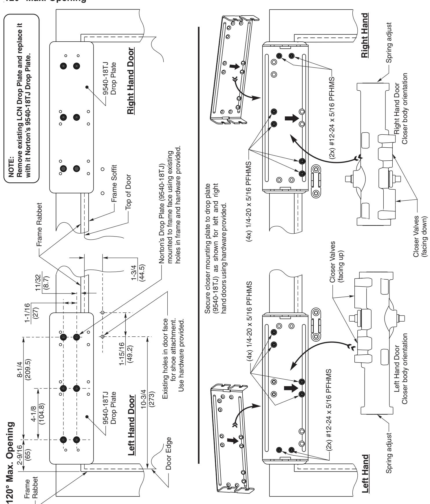
9540 Top Jamb Arm Template with 9540-18TJ Drop Plate 120° Max. Opening
ASSA ABLOY


Top Jamb Arm Installation Sequence
Remove existing LCN arm assembly, closer body and supporting mounting hardware. If existing drop plate is present, replace with Norton drop plate part number 9540-18TJ. See page 3, figure 3.2 of this instruction. NOTE: The existing LCN drop plate must be replaced with
NOTE: The existing LCN drop plate must be replaced with the proper Norton drop plate for the 9540 to perform correctly.
Inspect existing mounting holes for damage. Consult templates listed below to confirm existing holes are located in the proper position:
Page 13: 9540 Top Jamb Arm Mount with 9540-18TJ drop plate (Min. 1-3/4" frame face application)
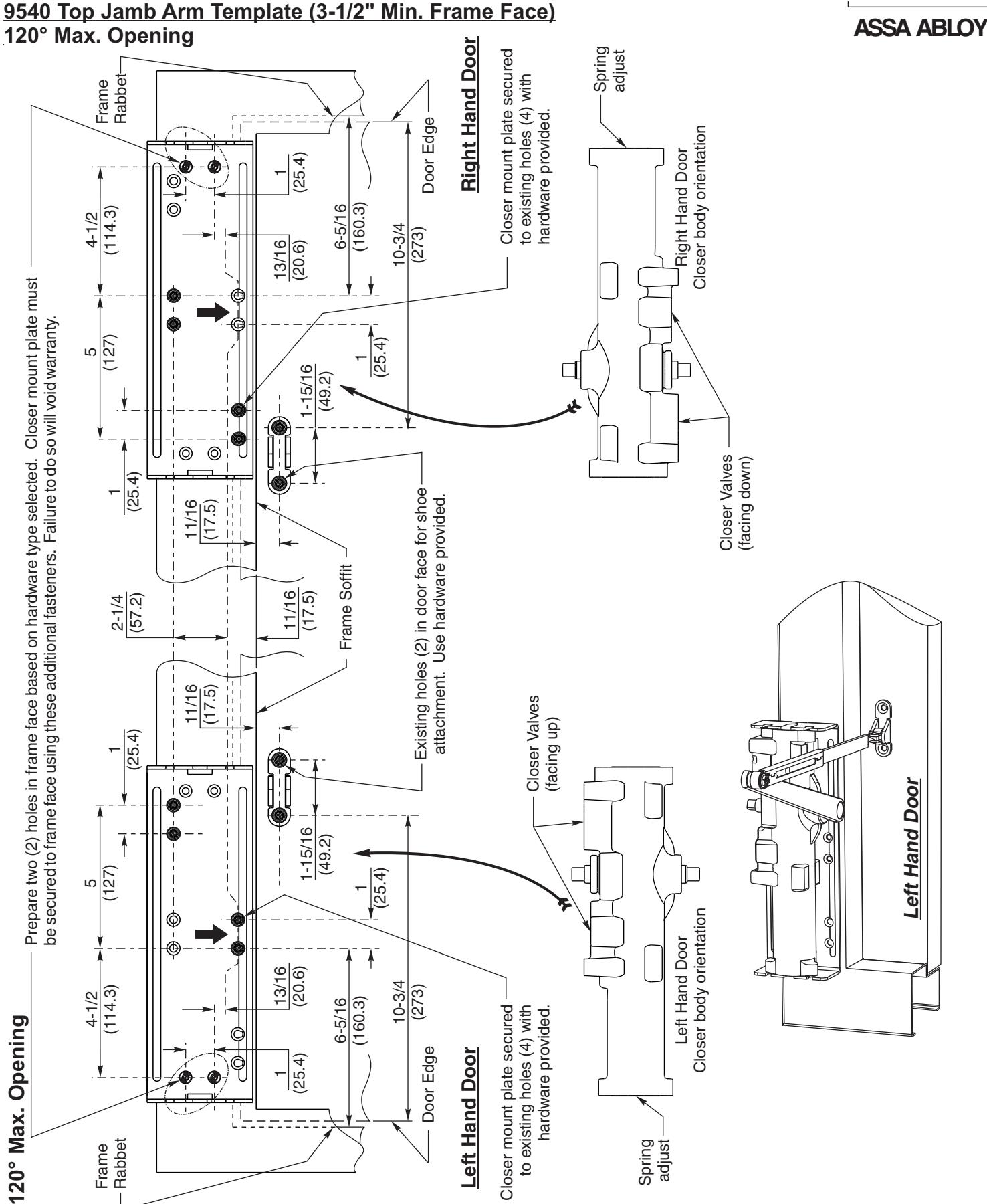
Page 14: 9540 Top Jamb Arm Mount (3-1/2" frame face application)
Improperly templated door or frame may affect door closer performance.
- 3. IMPORTANT: Using template on Page 14, locate and prepare two (2) additional holes for #12 screws for closer mounting plate. Screws will be located under the spring adjust end of closer when installed. See fastener chart page 4. (If installing closer body on Norton's Drop Plate page 13, these additional holes are already present on drop plate)
- 4. Secure drop plate (if required) and/or closer mounting plate to face of frame with hardware provided.
Note: See templates on page 13 and 14 for proper orientation of these plates in both Left Hand and Right Hand applications.
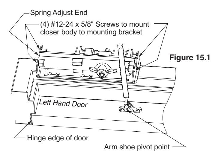
Fasten the closer body with spring adjust end TOWARD hinge edge of door and valve oriented as stated below to mounting plate with hardware provided (Figure 15.1).
Right hand door: Valves facing DOWN. Left hand door: Valves facing UP.
See templates on page 13 or 14 for illustrations of closer orientation.
6. Fasten arm shoe of the adjusting rod assembly to door face with hardware provided. Fasten with pivot point of shoe away from hinge. For additional 15% increase in closing force, position arm shoe with pivot point towards hinge edge of door as shown below. See figure 15.1 below; illustration shows left hand door.
Norton is a brand associated with Yale Security Inc., an ASSA ABLOY Group company. Copyright © 2016, Yale Security Inc. All rights reserved. Reproduction in whole or in part without the express written permission of Yale Security Inc. is prohibited.
- 7. Attach main arm to closer pinion as shown below (Figure 15.2) with main arm positioned 90° to frame face. Secure to pinion with arm screw provided.
- 8. Pre-load closer unit:
- Remove rod screw from adjusting rod. Insert adjusting rod into rectangular tube of main arm assembly (open door slightly if needed).
- With door in closed position, rotate main arm until adjusting rod is 90° with respect to door face as shown below (Figure 15.3).
- Re-install adjusting rod screw and tighten to maintain closer preload.
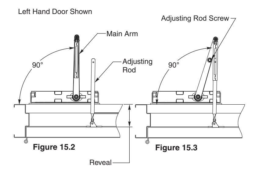
9540 ---- 2-9/16" Max. Reveal
J9540 ---- 2-9/16" to 4-13/16" Reveal
JL9540 ---- 4-13/16" to 8" Reveal
-
9. Closer Adjustments: See page 16 for more information.
- Adjust closing force using the spring adjust screw. Rotate screw clockwise (CW) to increase force. Rotate screw counter-clockwise (CCW) to decrease closing force. Use hex wrench provided.
- B) Adjust closing speed and latching speed of door using valves identified (Figure 16.1). Rotate valve clockwise (CW) to decrease speed. Rotate valve counter-clockwise (CCW) to increase door closing speed.
- C) Adjust backcheck intensity.
Rotate (CW) to increase backcheck intensity. Rotate (CCW) to de-crease backcheck intensity.
D) Delayed Action : (If equipped) Rotate valve (CW) to increase close delay time. Rotate (CCW) to de-crease close delay time

9540 Closer Unit Adjustments
Spring Power Adjustment
Locate spring power adjuster from illustration below and reference the size 1 through 6 adjustment chart (right).
All 9540 closer units are factory set for an approximate Size 3 setting. Adjust closer as necessary for door size using this chart. Re-adjustment may be required to suit prevailing conditions. Rotate power adjuster CLOCKWISE to increase closing force. Rotate power adjuster COUNTER-CLOCKWISE to decrease closing force.
ASSA ARIOV
| Size of D | oor |
Spring Power Adjustment
No. Full Turns Clockwise |
||||
|---|---|---|---|---|---|---|
| Interior | Exterior | Exterior | No. Full Turns Clockwise | Lquivalent | ||
|
In
Swing |
Out
Swing |
Regular & TJ Mounting |
Parallel Arm
Mounting |
Closer Size
(Approx.) |
||
| 2 ' 4" (712) | 2 ' 6" (764) | 1-5 | 2-7 | 3 | ||
| 2'6" (764) | 3 ' 0" (915) | 5-8 | 7-11 | 4 | ||
| 3 ' 0 '' (915) | 3 ' 6" (1067) | 2 ' 6" (764) | 8-13 | 11-15 | 5 | |
| 3 ' 6 '' (1067) | 4 ' 0" (1219) | 3 ' 0" (915) | 13-15 | 15-17 | 6 | |
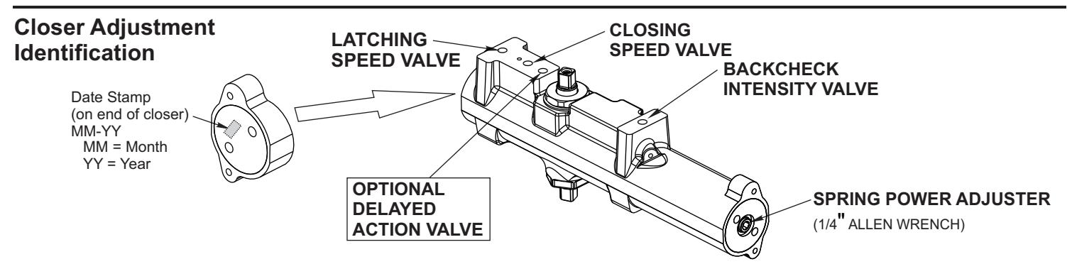
Valve Adjustment Delayed Action Option Backcheck
Closing Speed Valve
To adjust speed of door closing from fully open to a position 2" to 12" from closed, turn Closing Speed Valve CLOCKWISE to SLOW closing, COUNTER-CLOCKWISE to SPEED closing.
Latching Speed Valve
After closing speed has been obtained, turn latching speed valve CLOCKWISE to SLOW latching or COUNTER-CLOCKWISE to SPEED latching for last 2" to 12" of door travel.
NOTE: Set combination of CLOSING and LATCHING speeds to between 3 and 7 seconds Use of door by handicapped, elderly or small children may require even greater closing time.
Delayed Action Valve
Turn valve CLOCKWISE to SLOW closing, COUNTER-CLOCKWISE to SPEED closing. Delayed action may be adjusted from 5 seconds to 20 seconds, depending on degree of door swing. Delay occurs at the beginning of the door closing cycle from fully open down to 70°, where the closing speed valve then begins its control.
Backcheck Intensity Valve
Turn valve COUNTER-CLOCKWISE to reduce backcheck or CLOCKWISE to increase backcheck. (Backcheck should be set to give a soft cushioning action, not a sudden stop.)
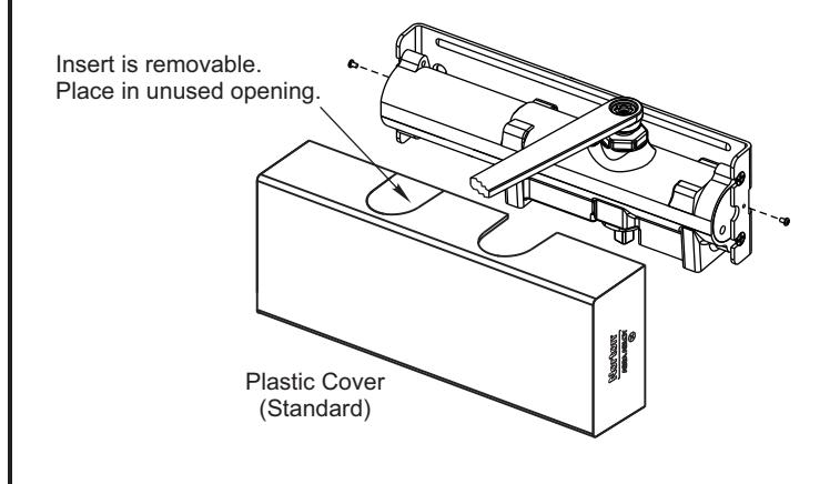
Installing Cover
- Slip cover over closer.
- Hold tightly against Closer Mounting Bracket surface.
- Secure on each side with 6-32 x 1/4" screws.
3000 Highway 74 East • Monroe, NC 28112 Tel: (877)-974-2255 • Fax: (800)-338-0965 www.nortondoorcontrols.com