Norton 7500 Series Door Closer UNIJ7500 UNIJ7700 Unitrol Top Jamb Arm Non-Hold Open or Hold Open Installation Instructions
Open the original PDF document
View PDF


Unitrol® Top Jamb Door Controls
UNI-J7500 (DA) (H) Series UNI-J7700 (DA) (H) Series
ASSA ABLOY
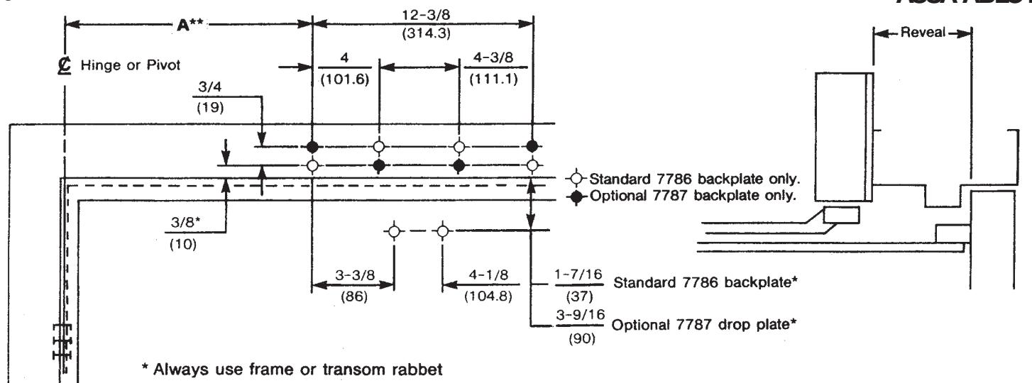
- Always use template covering door opening angle desired, correct door thickness and frame reveal, and door hanging hardware being used. Template dimensions in these instructions (page 2) cover frame reveals to 7-3/8" (187mm) in openings with 1-3/4" (44mm) thick doors hung on 4-1/2" (114mm) wide template hinges (figure 3), 3/4" (19mm) offset pivots (figure 3) or center pivots (figure 4).
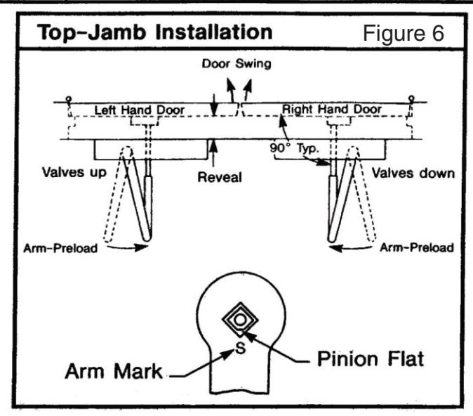
- Check hand of door: right or left (see figure 6, page 3). Make sure that door opens the full angle desired and latches without any binding action or interference. Note that hold open units will require that door swing five (5) degrees past hold open point to dead stop position.
- Always use sex nuts and bolts to mount arm foot and to mount closer plate in flush partitions.
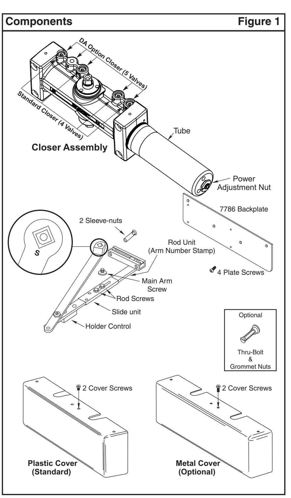
- Top Jamb Unitrols are supplied with arm rod UNI-E according to frame reveal. An arm number is stamped on these arm rods as shown on figures 3 and 4 (page 2).

Top Jamb Installation Template
Figure 2

4
| Figure 3 | |||||||||||||||
|---|---|---|---|---|---|---|---|---|---|---|---|---|---|---|---|
| Figure 4 | |||||||||||||||
|---|---|---|---|---|---|---|---|---|---|---|---|---|---|---|---|

| Figure 5 | ||||||||
|---|---|---|---|---|---|---|---|---|
| Installation Sequence | Remarks |
|---|---|
| See figure 2 and select template dimensions Note: Separate template required for other applications | 1¾" (44mm.) thick door on 4½" (114mm.) wide hinges or ¾" (19mm.) offset-pivots: figure 3. 1¾" (44mm.) thick door on center-pivots: figure 4. Frame reveals and door opening angles as charted: shock absorber will permit five (5) degrees of door travel beyond hold-open position. |
| Locate holes on frame trim face, stop-side. | Four (4) for 7786 backplate. |
| Locate holes on door | Two (2) for arm-foot. |
| Prepare door and frame for fasteners. | See chart "Preparation for Fasteners" (figure 5). Note: Use sex-bolts in frames of flush partitions. |
| Mount closer plate and install closer with power-adjustment-nut toward lock-stile. | Right hand-valves down Left hand-valves up |
| Disassemble rod-unit from arm-assembly and install on door. | Rod under shock-absorber and closest possible to lock-stile (see figures 2 and 6) |
| Mount main arm onto closer pinion shaft, aligning proper arm mark with pinion flat. Secure with main arm screw. | Arm Mark "S" See figure 6. |
| Insert connecting-rod into slide-unit and preload arm. Secure with rod-screws. |
Adjust rod to perpendicular with door.
See figure 6. |
| Adjust closer and install cover. | See "Unit Adjustment" on back page. |
Unit Adjustment
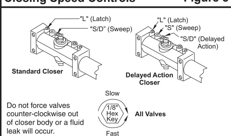
Closing Speed Controls (Figure 8.)
- · Valve "S" Controls Sweep Range.
- · Valve "L" Controls Latch Range.
Valve "D" Controls Optional Delay Range. Closing Power Control Figure 7 For UNI-J7500 Series Only Set closer to desired size. For recommended sizes, refer to the Power Adjustment Chart below. Install closer per instructions with the proper pre-load applied to the arm then adjust spring power. The power adjustment will not work properly if the closer spring is not pre-loaded. To increase power, use 11/16" wrench to turn power adjustment nut clockwise. To decrease power, turn nut counter clockwise DO NOT use a power drill or driver to turn adjustment nut. This will damage closer and void warranty. Closing Speed Controls Figure 8 "L" (Latch) (Latch)
| Power Adjustment Chart Figure | ||||||
|---|---|---|---|---|---|---|
| Door | UNI-J7500 | |||||
| Size | Turns fr | om Zero | ||||
|
inches
(mm) |
Interior
Door |
Exterior
Door |
||||
|
28-32
(711-813) |
0 | 3 | ||||
|
33-36
(838-914) |
2 | 5 | ||||
|
37-42
(940-1067) |
5 | 7 | ||||
|
43-48
(1092-1219) |
8 | 11 | ||||
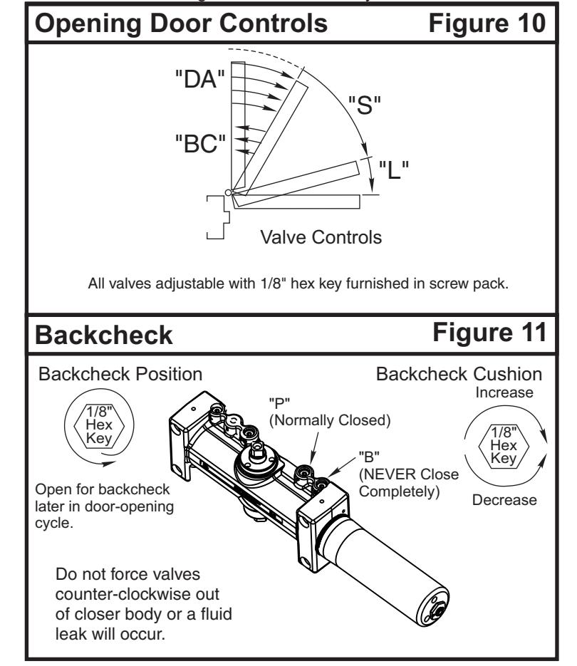
Opening Speed Controls (Figure 10.)
- Backcheck ("B") valve controls the hydraulic resistance to door opening. NEVER close this valve completely – it is not to provide a positive stop.
- Backcheck position ("P") valve controls the door angle where backcheck cushioning starts. Valve normally closed.
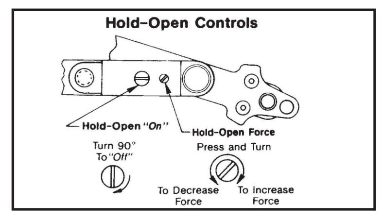
Hold Open controls are at arm elbow (models suffixed "H"). To select hold open on or hold open off and to adjust the hold open force, use screwdriver as illustrated below.

ASSA ABLOY, the global leader in door opening solutions