Norton 7500 Series Door Closer Tri-Style (Regular,Parallel,Top Jamb) Non-Hold Open Installation Instructions
Open the original PDF document
View PDF

Installation Instructions
7500 Series
P7500
Multi Size - 1 thru 6 Non Hold Open Door Closers Models - 7500 J7500 JL7500
CAUTION
An incorrectly installed or improperly adjusted door closer can cause property damage or personal injury. These instructions should be followed to avoid the possibility of misapplication or misadjustment.
- With or without suffix "DA" (Delayed Action) closing.
- With or without suffix "M" with metal Cover.
Note:

The closing force for series 7500 door closer is adjustable from a size 1 to a size 6, as outlined in ANSI Standard A156.4. When this series of door closer is installed and adjusted to conform to ADA reduced opening force requirements (5 lbs max.) for interior doors, it may not have adequate closing force to reliably close and latch the door. Power adjustments charted on pages 3,4 and 5 are recommended where possible, to ensure proper door control.
For Special Applications a separate door and frame preparation template is packed with these instructions. Use this instruction sheet for installation sequence and closer adjustments only.
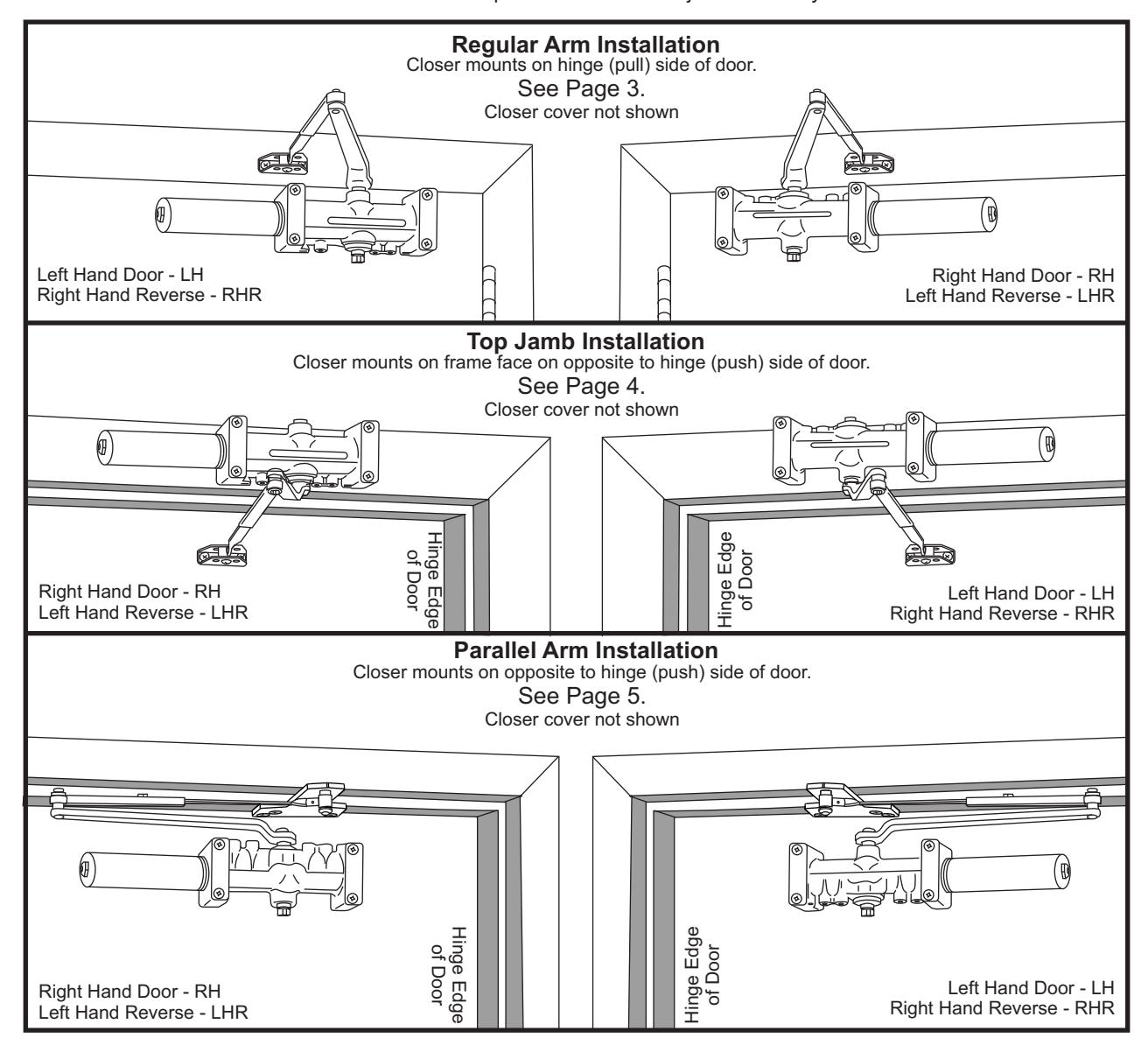

- It is recommended that the door, on which the door closer will be installed, be hung on ball bearing hinges. Door must swing freely.
- A separate door stop, supplied by others, is recommended to prevent damage to the door closer, closer arm; or to the door, frame or adjacent walls.
- · Door and Frame must be properly reinforced, or use of special fasteners employed, to prevent the mounting screws from pulling out.
- All dimensions are given in inches with corresponding metric dimensions (millimeters) in parentheses.
- Door closer should never be installed on the exterior of a building.
| Preparation for Fasteners Figure 2 | |||
|---|---|---|---|
| Fasteners | Door or Frame | Drill-Sizes | |
| Standard | Self-Drilling Screw | Aluminum or Metal | No drill required |
|
Wood
(see Note) |
3/16" (4.30 mm) | ||
| 1/4" - 20 machine screw | Metal |
Drill: #7 (0.201" dia.)
Tap: 1/4" - 20 |
|
| Optional | Sleeve nuts and bolts |
Hollow
Metal |
9/32" (7 mm) through;
3/8" (9.5 mm) door face opposite to closer |
|
Aluminum
or Wood |
3/8" (9.5 mm) through | ||
| Through-bolts and grommet-nuts | All |
9/32" (7 mm);
3/8" (9.5 mm) dia. x 3/8" (9.5 mm) deep on door opposite to closer |
|
Note: Wood doors/frames. Pilot hole must be drilled when using Self-Drilling Screws.
Always consult door/frame manufacturer for fastener compatibility with the material of their door/frame.
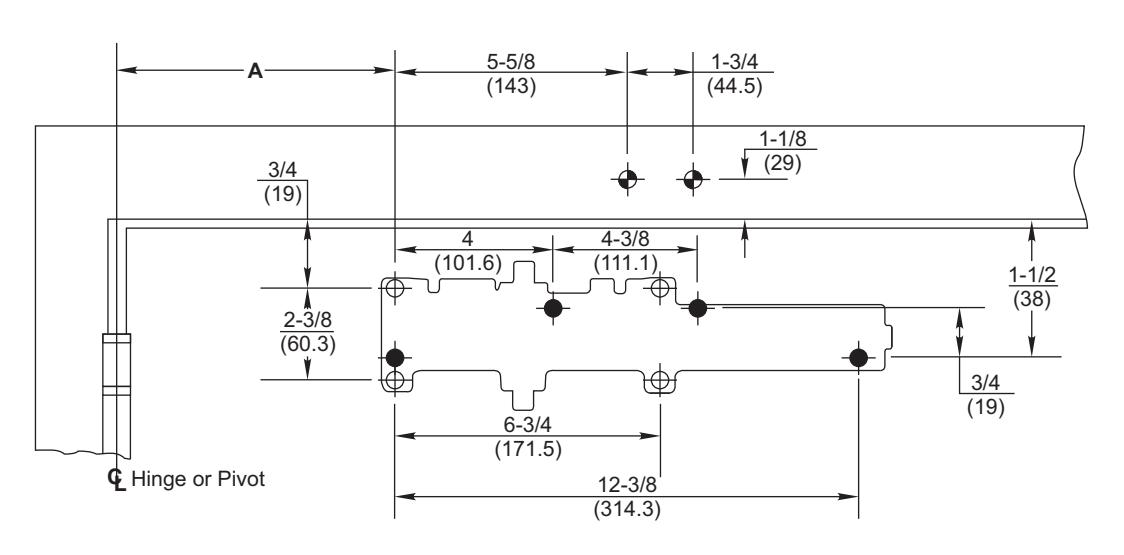
Regular Arm Template


Do Not Scale Drawing
Right Hand Door Shown
Dimensions are in inches (mm).
7786 Backplate Mounting Hole Only
| Dimension A | ||
|---|---|---|
| Dillicitatori | ||
| Opening | inches | mm |
| To 100° | 7-5/8 | 194 |
| 101° to 120° | 6-5/8 | 168 |
| 121° to 150° | 4-5/8 | 117 |
| 151° to 180° | 4-1/8 | 105 |
Installation Sequence
Select angle of opening and use dimensions shown in template and chart to locate 4 holes on door for closer body (or 4 holes for optional 7786 backplate) and 2 holes frame face for arm shoe.
For applications that are different from above, a separate template will be supplied for door and frame preparation.
- Prepare door and frame for fasteners using "Preparation for Fasteners" chart, Figure 2, Page 2.
- Fasten optional 7786 backplate to door, only if it is required for the door conditions.
- Install closer body with tube end away from hinge, with valves:
Down for Left Hand door UP for Right Hand door.
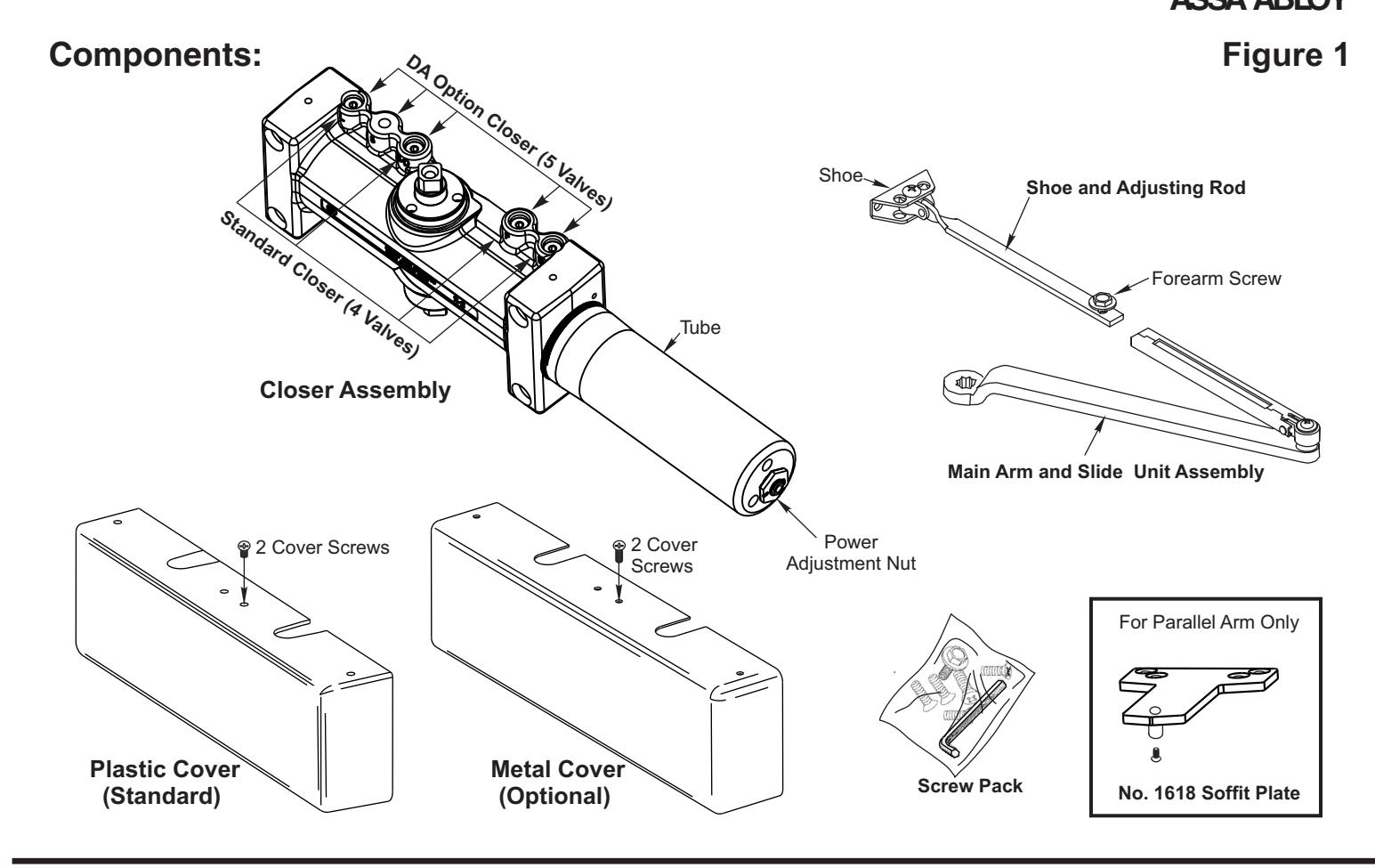
- Fasten arm shoe (with adjusting rod) Figure 1, Page 2 to frame face.
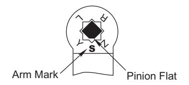
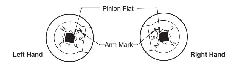
- Install main arm onto closer pinion shaft, aligning arm mark "S" with the one flat corner of the square shaft "Pinion Flat", see illustration at right. Secure with hex washerhead main arm screw.
Remove forearm screw from adjusting rod on frame and open door slightly to slide adjusting rod into slide unit. Close door and rotate arm away from hinge until adjusting rod and slide unit are perpendicular (at a 90° angle) to door. Install and tighten forearm screw.
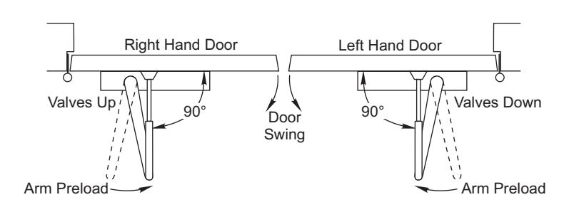
Make closer adjustments, if required, using information below and on Page 6, then install closer cover.
| Power Adjustment Chart | |||
|---|---|---|---|
|
Maximum
Interior Door Size inches / (mm) |
Maximum
Exterior Door Size inches / (mm) |
Turns
from Zero |
|
| 32 / (813) | 28 / (711) | 5 | |
| 36 / (914) | 34 / (864) | 8-1/2 | |
| 42 / (1067) | 38 / (965) | 11 | |
| 52 / (1321) | 42 / (1067) | 13-1/2 | |
| 60 / (1524) | 48 / (1219) | 16-1/2 | |
| NOTE: Maximum of 16-1/2 turns | |||
(360°) of Power Adjustment Nut.
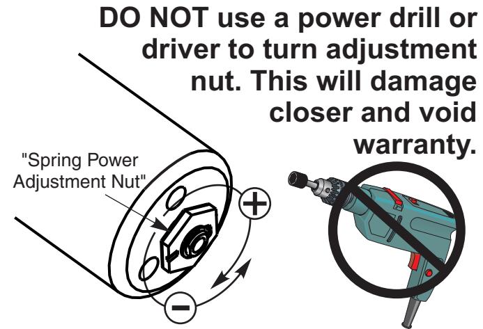
Install closer per instructions with the proper pre-load applied to the arm then adjust spring power. The power adjustment will not work properly if the closer spring is not pre-loaded. To increase power, use 11/16" wrench to turn power adjustment nut clockwise. To decrease power, turn nut counter clockwise.
Top Jamb

ASSA ABLOY
Do Not Scale Drawing
Left Hand Door Shown
Dimensions are in inches (mm).
7786 Backplate Mounting Hole Only
| Dimension A | ||
|---|---|---|
| Opening | inches | mm |
| To 100° | 7-5/8 | 194 |
| 101° to 120° | 6-5/8 | 168 |
| 121° to 150° | 4-5/8 | 117 |
| 151° to 180° | 4-1/8 | 105 |
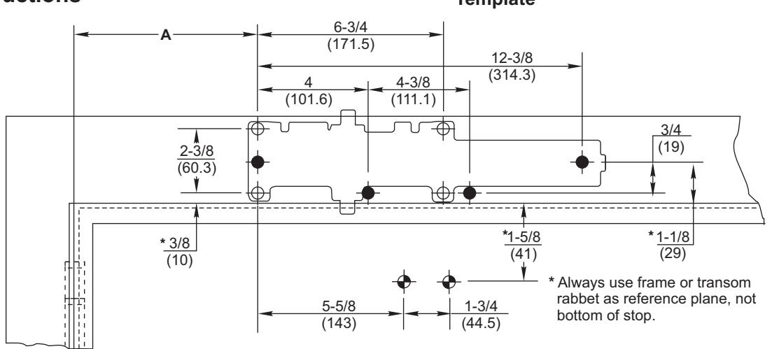
Installation Sequence
Hinge or Pivot
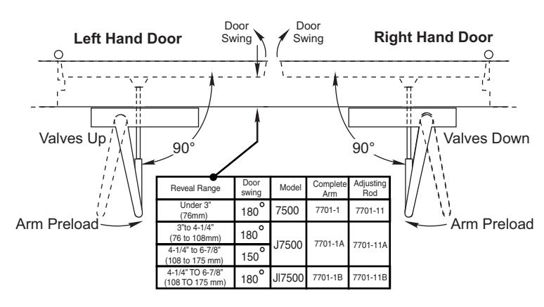
Select angle of opening and use dimensions shown in template and chart to locate 4 holes on frame for closer body (or 4 holes for optional 7786 backplate) and 2 holes door for arm shoe.
For applications that are different from above, a separate template will be supplied for door and frame preparation.
- Prepare door and frame for fasteners using "Preparation for Fasteners" chart, Figure 2, Page 2.
- Fasten optional 7786 backplate to frame, only if it is required for the frame conditions.
- Install closer body with tube end away from hinge, with valves:
Up for Left Hand door Down for Right Hand door.
Fasten arm shoe (with adjusting rod) Figure 1, Page 2 to door face.
Note that a longer adjusting rod or different arm might be required for your frame conditions, see illustration with "Reveal Range" chart to the right.
Install main arm onto closer pinion shaft, aligning arm mark "S" with the one flat corner of the square shaft, "Pinion Flat", see illustration at right. Secure with hex washerhead main arm screw.
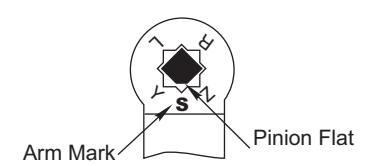
Remove forearm screw from adjusting rod on door and open door slightly to slide adjusting rod into slide unit. Close door and rotate arm away from hinge until adjusting rod and slide unit are perpendicular (at a 90° angle) to door. Install and tighten forearm screw.
• Make closer adjustments, if required, using information below and on Page 6, then install closer cover.
| Power Adjustment Chart | |||
|---|---|---|---|
|
Maximum
Interior Door Size inches / (mm) |
Maximum
Exterior Door Size inches / (mm) |
Turns
from Zero |
|
| 32 / (813) | 28 / (711) | 5 | |
| 36 / (914) | 34 / (864) | 8-1/2 | |
| 42 / (1067) | 38 / (965) | 11 | |
| 52 / (1321) | 42 / (1067) | 13-1/2 | |
| 60 / (1524) | 48 / (1219) | 16-1/2 | |
| NOTE: Maximum of 16-1/2 turns | |||
(360°) of Power Adjustment Nut.
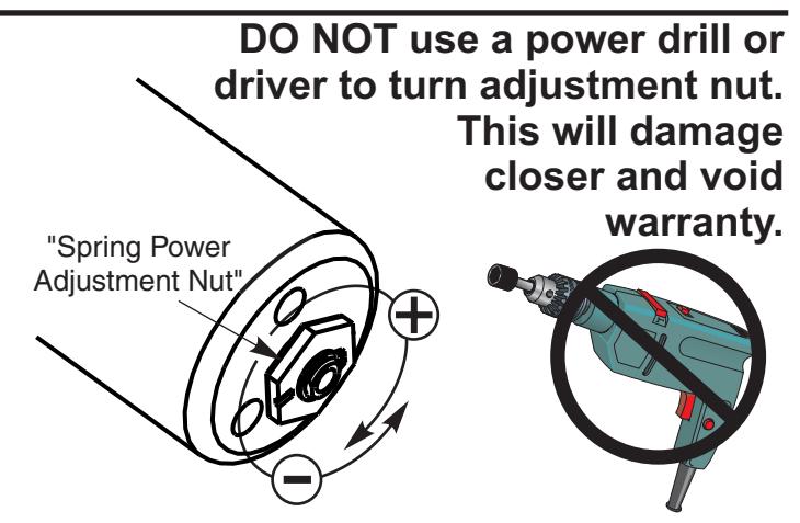
Install closer per instructions with the proper pre-load applied to the arm then adjust spring power. The power adjustment will not work properly if the closer spring is not pre-loaded. To increase power, use 11/16" wrench to turn power adjustment nut clockwise. To decrease power, turn nut counter clockwise.
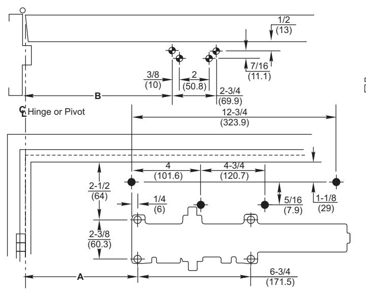
Parallel Arm Template

ASSA ABLOY
Installation Sequence
• Select angle of opening and use dimensions shown in template and chart to locate 4 holes on door for closer body (or 4 holes for optional 7788 dropplate) and 4 holes on underside of frame for soffit plate.
For applications that are different from above, a separate template will be supplied for door and frame preparation.
- Prepare door and frame for fasteners using "Preparation for Fasteners" chart, Figure 2, Page 2.
- Fasten optional 7788 dropplate to door, only if it is required for the door conditions.
- Install closer body with tube end away from hinge, with valves: Down for Left Hand door UP for Right Hand door.
- Fasten soffit plate to frame.
- Install adjusting rod onto soffit plate and secure with screw and washer assembly from screw pack.
- Install main arm onto closer pinion shaft using illustration at right. The one flat corner of the square shaft " Pinion Flat ", must be aligned with the corner mark on arm:
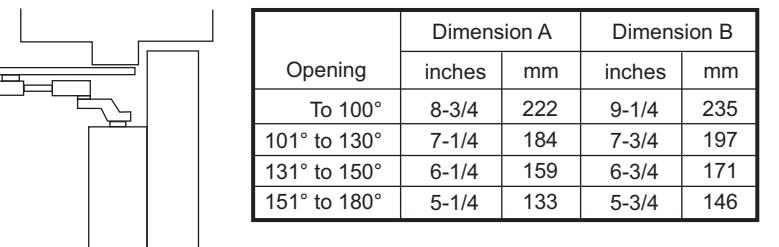
7788 Dropplate Mounting Hole Only
Do Not Scale Drawing Left Hand Door Shown Dimensions are in inches (mm).
Arm mark "Y" for Right Hand door Arm mark "Z" for Left Hand door
This requires that the pinion shaft be rotated approximately 50 degrees to get correct alignment.
• Secure with hex washerhead main arm screw.
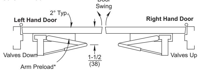
- Remove forearm screw from adjusting rod on frame and open door slightly to slide adjusting rod into slide unit.
- Door • Close door and pull arm away from door face so elbow is 1-1/2" (38mm) off of door face. Reinstall and tighten forearm screw in rod.
• Make closer adjustments, if required, using information below and on Page 6, then install closer cover.
| Power Adjustment Chart | |||
|---|---|---|---|
|
Maximum
Interior Door Size |
Maximum
Exterior Door Size inches / (mm) inches / (mm) |
Turns
from Zero |
|
| 30 / (762) | 26 / (660) | 7 | |
| 34 / (864) | 30 / (762) | 9 | |
| 38 / (965) | 36 / (914) | 12-1/2 | |
| 48 / (1219) | 42 / (1067) | 14-1/2 | |
| 54 / (1372) | 48 / (1219) | 16-1/2 | |
NOTE: Maximum of 16-1/2 turns (360°) of Power Adjustment Nut.
Install closer per instructions with the proper pre-load applied to the arm then adjust spring power. The power adjustment will not work properly if the closer spring is not pre-loaded. To increase power, use 11/16" wrench to turn power adjustment nut clockwise. To decrease power, turn nut counter clockwise.
Unit Adjustment
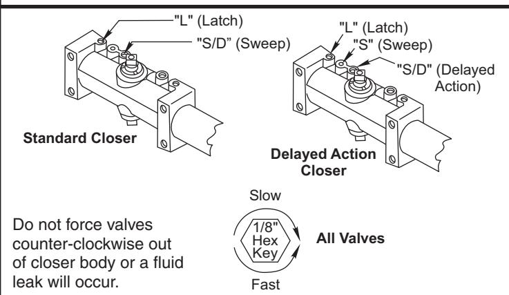
Closing Speed Controls (Figure 4A or 4B and 5.)
- Valve "S/D" Controls Sweep Range on Standard closer (or Delayed Range on Delayed Action closer).
- · Valve "L" Controls Latch Range.
- Valve "S" Controls Sweep only on Delayed Action closer.
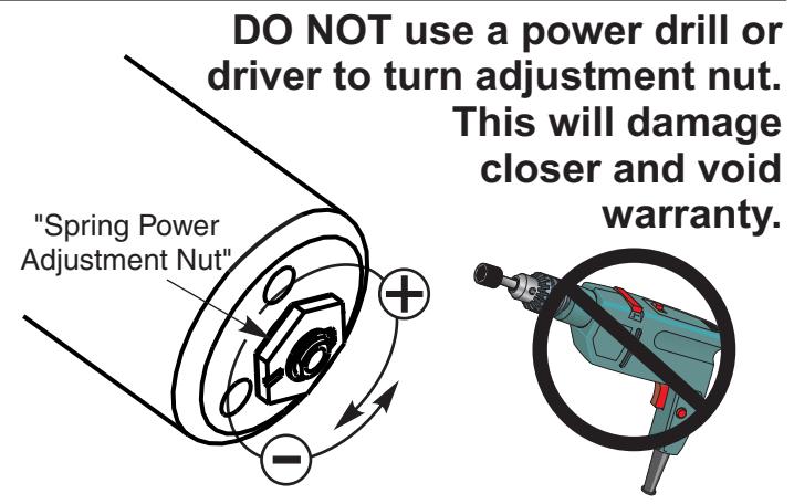
Closing Power Control Figure 3 Set closer to desired size. For recommended sizes, refer to the Power Adjustment Chart on pages 3,4,& 5. Install closer per instructions with the proper pre-load applied to the arm then adjust spring power. The power adjustment will not work properly if the closer spring is not pre-loaded. To increase power, use 11/16" wrench to turn power adjustment nut clockwise. To decrease power, turn nut counter clockwise. DO NOT use a power drill or driver to turn adjustment nut. This will damage closer and void warranty. Closing Speed Controls Figure 4
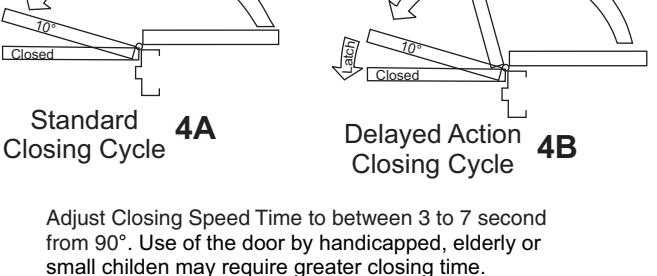
Figure 5 Closing Speed Controls
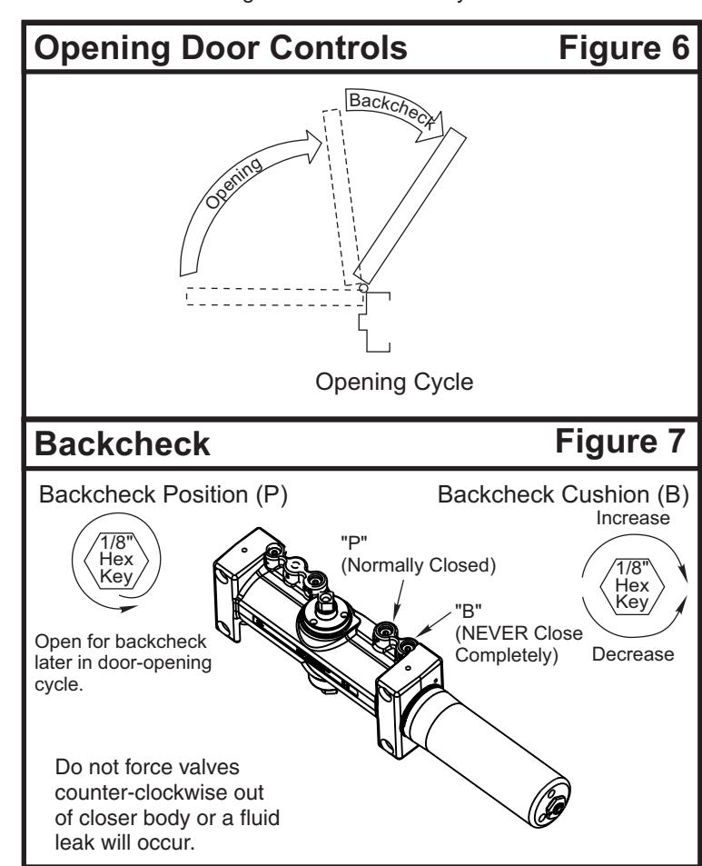
Opening Door Control (Figure 6.)
- Backcheck ("B") valve controls the hydraulic resistance to door opening. NEVER close this valve completely – it is not to provide a positive stop.
- Backcheck position ("P") valve controls the door angle where backcheck cushioning starts. Valve normally closed.
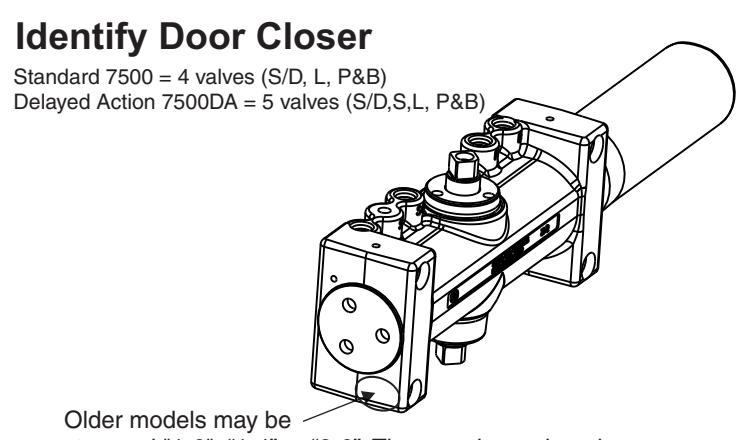
stamped "1-6", "1-4" or "2-6". They can be replaced with the newer "1-6" model which has no stamp.

Tel: (877)-974-2255 • Fax: (800)-338-0965 www.nortondoorcontrols.com