Norton 7500 Series Door Closer JS7500 Top Jamb Non-Hold Open Installation Instructions
Open the original PDF document
View PDF

Installation Instructions

An Incorrectly installed or improperly adjusted door closer can cause property damage or personal injury. These installation instructions should be followed to avoid the possibility of misapplication or misadjustment.
7500 Series
Non Hold Open Models
Top Jamb Installation Multi Size 1 thru 6
JS7500
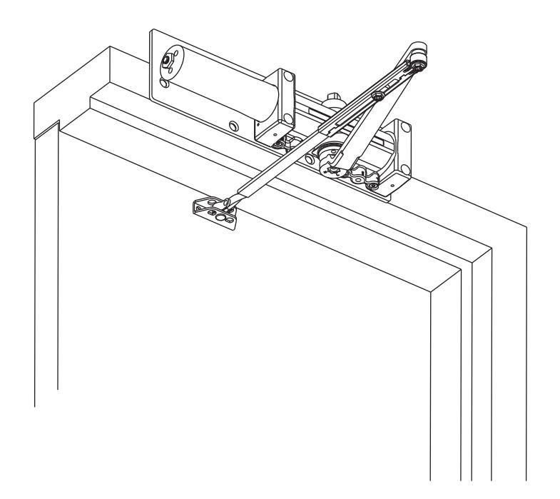
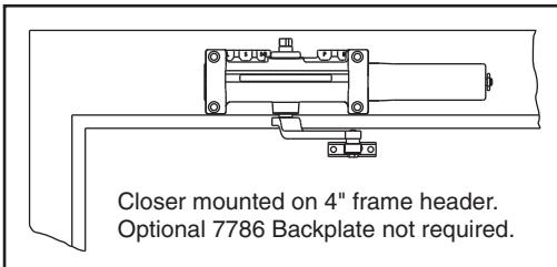
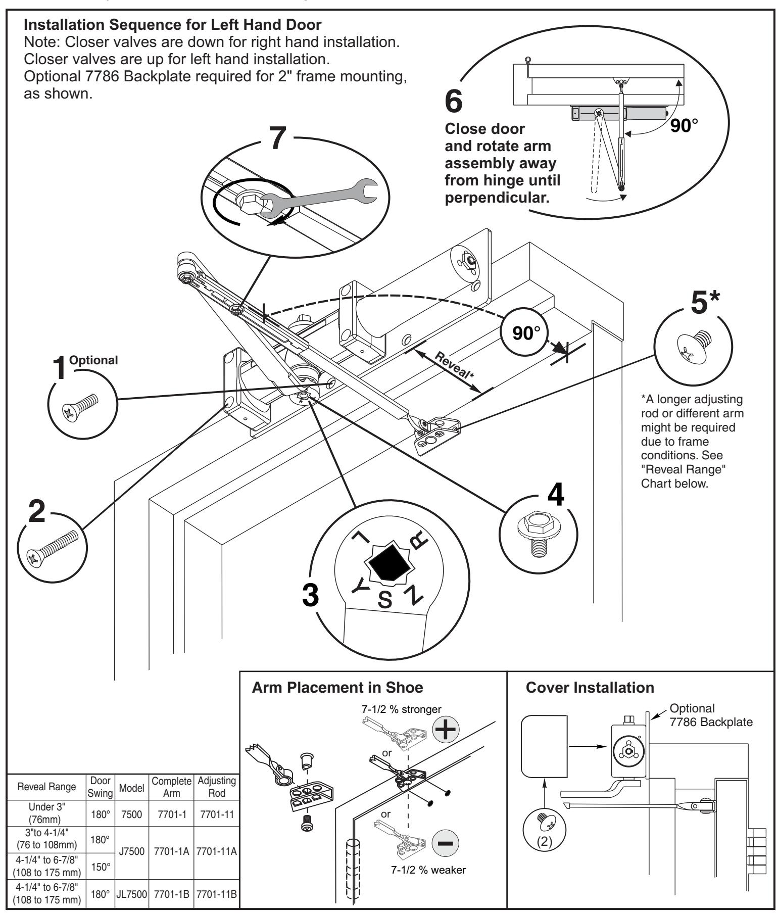
Illustrations show product mounted on 2" frame face with optional 7786 backplate (sold separately). Optional backplate is not required on 4" frame face.
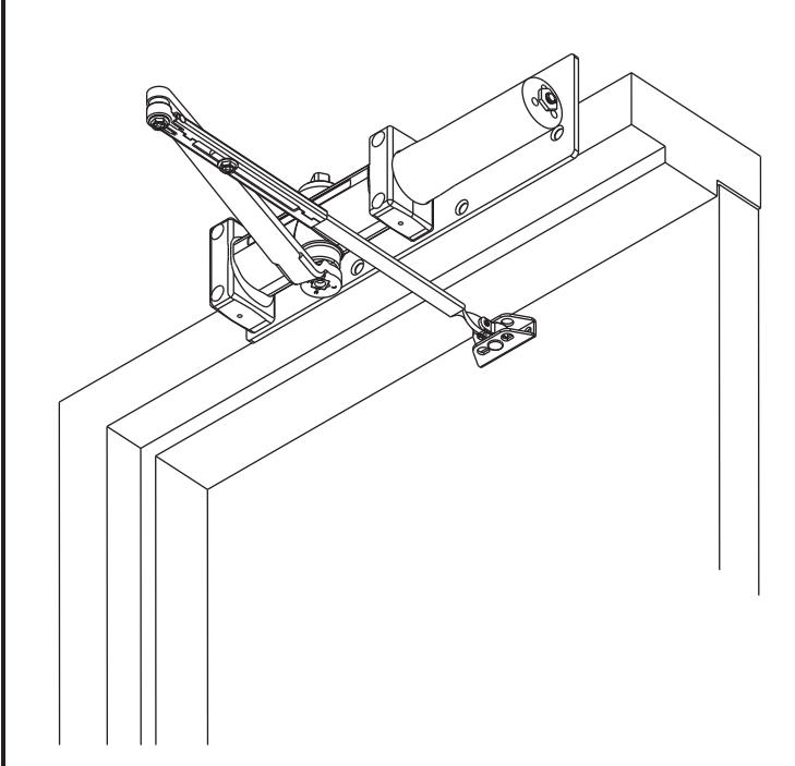
Left Hand Door - LH Right Hand Reverse - RHR
Right Hand Door - RH Left Hand Reverse - LHR
- "DA" suffix (Delayed Action) is an optional feature.
- NOTE: For special applications a separate door and frame preparation template is packed with these instructions. Use this instruction sheet for installation sequence and closer adjustments only.
- Doors should be hung on ball bearing or anti-friction hinges.
- A separate door stop is recommended.
- Door and frame must be properly reinforced.
- Always adjust spring power before adjusting control valves.
- Adjust closing time speed between 3 and 7 seconds from 90° to 0°. Greater closing times may be required for elderly or handicapped.
- These door closers should NOT be installed on the exposed side (weather side) of exterior doors.
7500 Series
Norton<sup>a</sup>
Non Hold Open Door Closers — Top Jamb
ASSA ABLOY
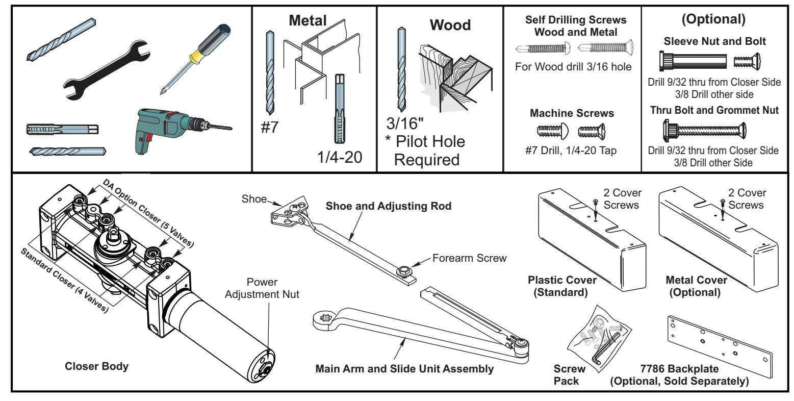
Mark and Drill Holes
This template for use with standard butt hinges or 3/4 offset pivots. For all other hardware, please consult factory for template.
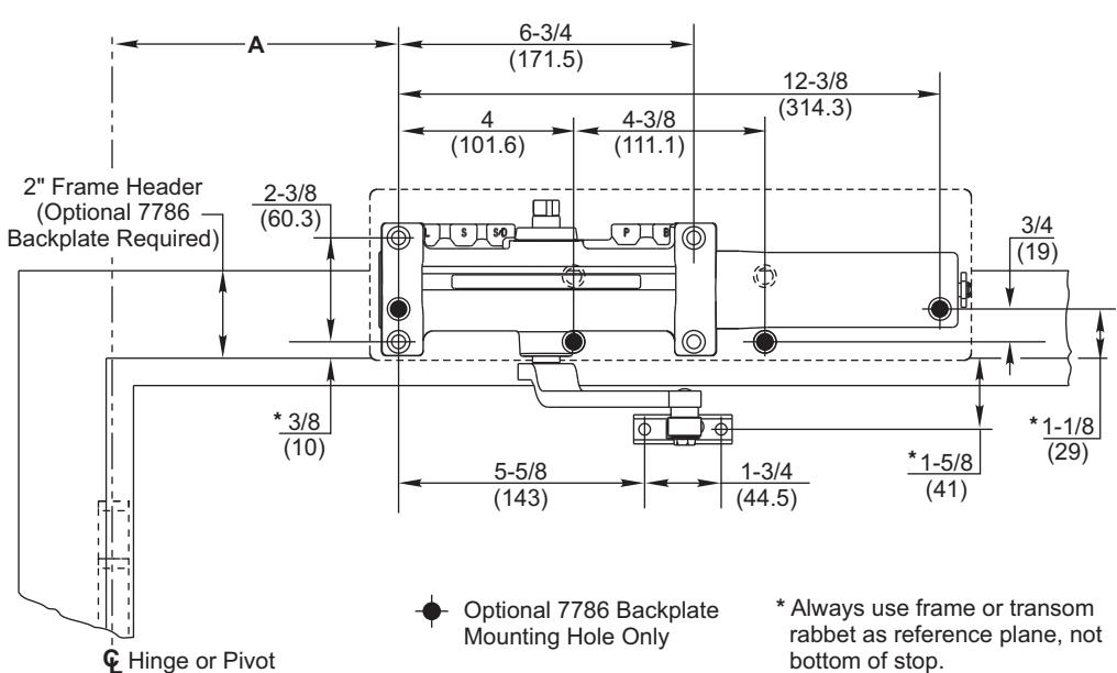
- Opening Dimension A To 100° 7-5/8 194 101° to 120° 6-5/8 168 121° to 150° 4-5/8 117 151° to 180° 4-1/8 105
- Do not scale drawing.
- Left hand door shown, right hand opposite.
- Dimensions are in inches / (mm)
- Hollow metal door require channel or box type reinforcement when through bolt mount is specified.
- Sex bolts required for wood or plastic faced fire door mounting.
- Minimum thickness recommended for reinforcements in hollow metal doors and frames: .146" (2.66mm) unless otherwise specified.
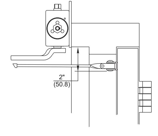
- Arm with Hold Open function is NOT permitted on fire door.
- Maximum width hinge for this template is 5" (127).
- Closer valves are facing down for right hand. Valves are facing up for left hand.
7500 Series
Norton<sup>a</sup>
Non Hold Open Door Closers — Top Jamb
ASSA ABLOY
Spring Power Adjust
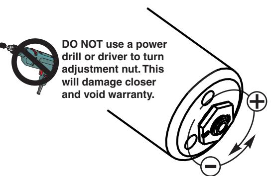
Install closer per instructions with the proper pre-load applied to the arm then adjust spring power. The power adjustment will not work properly if the closer spring is not pre-loaded.
To increase power, use 11/16" wrench to turn power adjustment nut clockwise. To decrease power, turn nut counter clockwise.
| Power Adjustment Chart | ||
|---|---|---|
|
Maximum
Interior Door Size inches / (mm) |
Maximum
Exterior Door Size inches / (mm) |
Turns
from Zero |
| 32 / (813) | 28 / (711) | 5 |
| 36 / (914) | 34 / (864) | 8-1/2 |
| 42 / (1067) | 38 / (965) | 11 |
| 52 / (1321) | 42 / (1067) | 13-1/2 |
| 60 / (1524) | 48 / (1219) | 16-1/2 |
NOTE: Maximum of 16-1/2 turns (360°) of Power Adjustment Nut.

By law the Americans with Disabilities Act (ADA) may require that door closer installation comply with accessability guidelines.
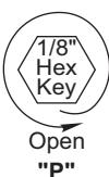
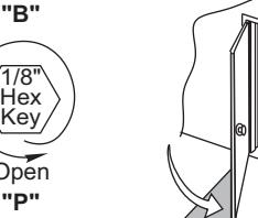
Use 1/8" hex key for these adjustments.
of closer body or a fluid leak will occur.
Do not force valves counter-clockwise out
Standard Closer (4 Valves)
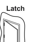
"L" (Latch)
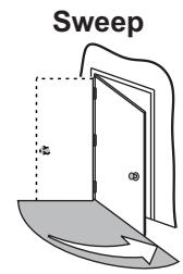
"S" (Sweep)
Normally Closed
The closing force for series 7500 door closer is adjustable from a size 1 to a size 6, as outlined in ANSI Standard A156.4. When these series of door closer is installed and adjusted to conform to ADA reduced opening force requirements (5 lbs max.) for interior doors, they may not have adequate closing force to reliably close and latch the door. Power adjustments charted on this page are recommended where possible, to ensure proper door control.
'S" (Sweep)
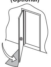
"D" (Delayed Action)
(Latch)
Adjust Closing Speed Time to between 3 to 7 seconds from 90°. Use of the door by handicapped, elderly or small children may require greater closing time.
"P" (Backcheck Position)
"B" (Backcheck Cushion)
NEVER Close Completely
DA Option Closer (5 Valves)
Normally Closed
Slow 1/8" Hex Key
Fast
Increase 1/8" Hex Key
Decrease
"L", "S", "D"
"R"
Delayed Action (Optional)
Backcheck
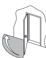
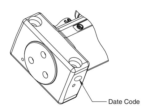
To Identify Date Code:
"P" (Backcheck Position)
"B" (Backcheck Cushion)
NEVER Close Completely

ASSA ABLOY
3000 Highway 74 East • Monroe, NC 28112 Tel: (877)-974-2255 • Fax: (800)-338-0965 www.nortondoorcontrols.com