Lp Lock Nl Lock Instructions for LP Rotobolt
Open the original PDF document
View PDF

Base Line Installation Instructions (8-32 Screws)
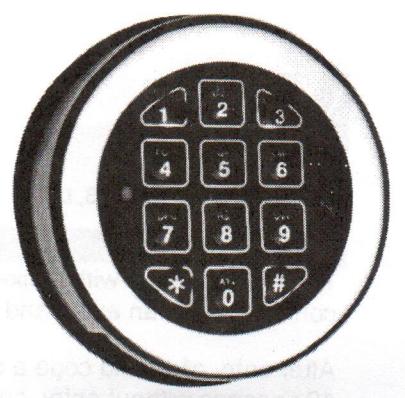
CHARACTERISTICS
The integrated battery compartment in the bottom of the Base Line entry unit opens by moving a slider from left to right. Cable length is approximately 30 cm (11-3/4").
DIMENSIONS/MOUNTING INSTRUCTIONS
The diameter of the cable hole should be a minimum 9 mm (3/8"), maximum 12 mm (7/16"). The hole must be deburred well to avoid damage to the cable.
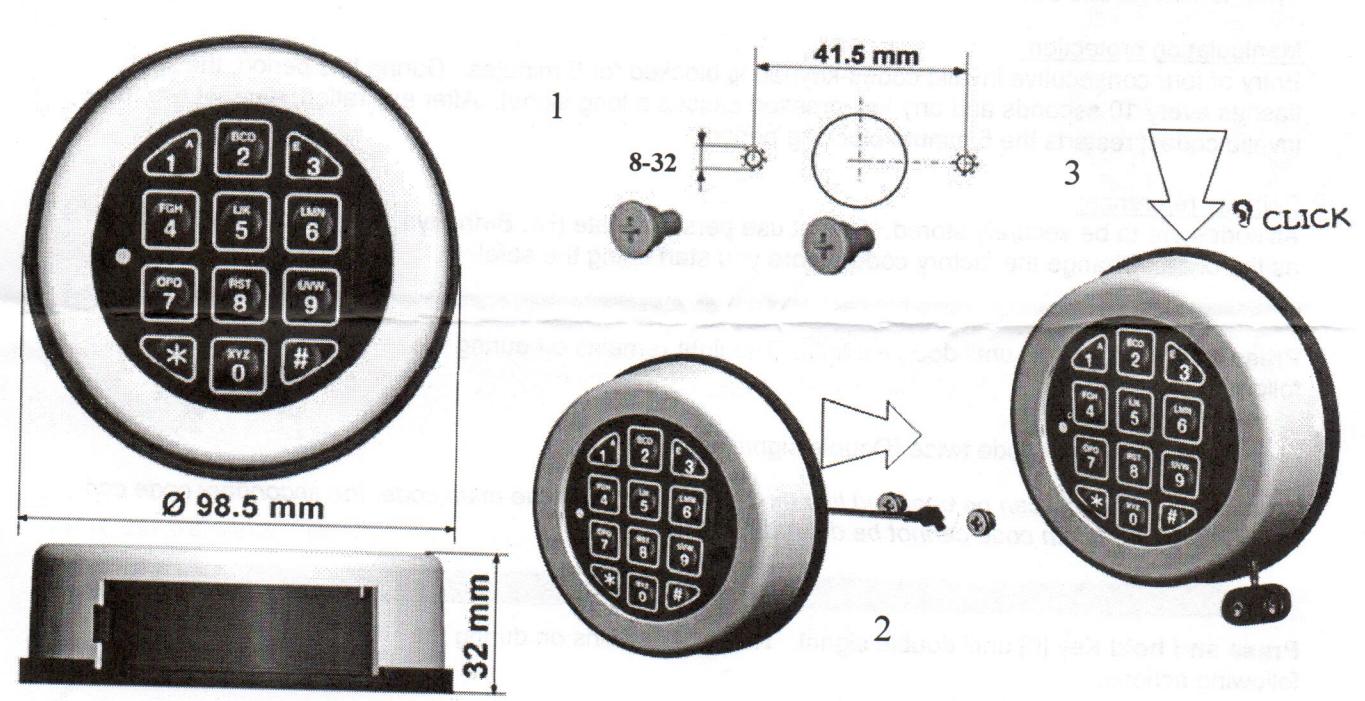
Affix the two 8-32 shoulder screws (1). Route the cable through the cable hole and slide the unit onto the shoulder screws (2). The back of the unit must touch the door surface. Control cable routing, then push the unit down until it snaps on positively (3).
The Base Line entry unit should not be removed!
Connect one (1) battery to the battery clip. Only use 9V-ALKALINE batteries from brand name manufacturers like DURACELL™ or Eveready™. A series of signals indicates that the battery is weak and must be replaced.
Base Line inputs are available in various finishes; Textured Black, Matte Chrome (shown above), Bright Chrome and Bright Brass.
Base Line Key Pad Set-Up Instructions
General
The lock operates with a six-digit code. A secondary code can be added. When pressed, each key is confirmed with an audio and light signal.
After entry of a valid code a double signal will follow. An invalid entry is followed by a long signal. After 10 seconds without entry, current code being entered will be cancelled.
Onen
Enter code (factory code = 1-2-3-4-5-6), unlock door and open. If not opened within 3 seconds, the lock secures automatically. If code entry failed on first attempt wait 20 seconds before re-entering. Three long beeps indicate the lock bolt is jammed. Release the handle and re-enter the code.
Locking:
Close door and turn handle fully to closing position. The lock is secured. Control blocking status by trying to turn handle back.
Manipulation protection:
Entry of four consecutive invalid codes-keypad is blocked for 5 minutes. During this period, the light flashes every 10 seconds and any key pressed causes a long signal. After expiration, entry of two more invalid codes, restarts the 5 minute blocking period.
Security reference:
All codes are to be securely stored. Do not use personal date (i.e. Birthdays, telephone numbers etc.) as the code. Change the factory code before you start using the safe!
Activate the second opening code:
Press and hold Key [1] until double signal. The light remains on during the following action.
- •Enter main code.
- Enter Secondary code twice (Double signal after each)
(The secondary code can be changed like the main code. With the main code, the secondary code can be deleted. The main code cannot be deleted).
Check code
Press and hold Key [0] until double signal. The light remains on during the following actions.
- Enter old code (double signal)
- Enter new code (double signal) and repeat new code (double signal)
In case of entry errors (long signal), the old code remains valid.
Delete the secondary code
Press and hold Key [3] until double signal. The light remains on during the following actions.
Enter main code. The secondary code is deleted.
Current supply / battery change
A series of signals indicates that the battery is weak and must be replaced. Use only 9V ALKALINE—batteries! The battery compartment is located at the bottom of the entry unit.


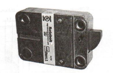
CHARACTERISTICS
The RotoBolt lock can be mounted in all four mounting directions. Further, by flipping the lock, both blocking directions can be realized. The mounting dimensions are standard. The lock is delivered with US 1/4 - 20 screws. The Electronics feature a 6-digit Manager code that can be changed by the user. With the manager code a secondary user code can be activated and deleted. If a valid code has been entered, the locks electronics removes the blocking for 3 seconds and the boltwork can be moved into the OPEN position and subsequently retracting the bolt inside the lock case. When moving the boltwork into LOCKED position the RotoBolt automatically secures. LpLOCKS recommends Duracell™ or Eveready™ ALAKALINE batteries.
ENTRY UNITS
The RotoBolt is compatible with the following LpLOCKS Entry units;
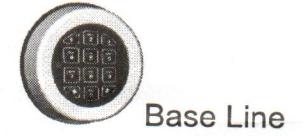
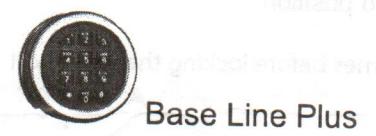
(Separate technical instructions for Entry units available)
BOLTWORK REQUIREMENTS and MOUNTING INSTRUCTIONS
The maximum allowed cable/spindle hole diameter is 11 mm (7/16") (if located under the lock body).
If the RotoBolt lock is used in conjunction with another lock, the boltwork must be constructed in a way that the RotoBolt secures first.

Only use supplied screws to mount the lock. Tighten the screws securely so the lock body is attached firmly to the flat mounting surface.
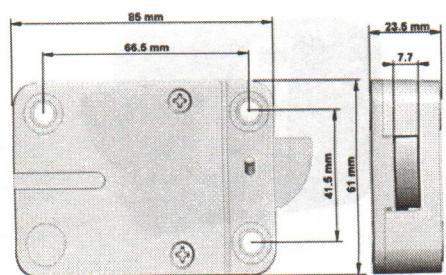
Mount the entry unit following the manufacturer's instructions.
housing labeled "ENT". Check that the connector is completely seated. To remove the connector, carefully lift it and pull it out.
In the entry unit or battery box connect a 9V-ALKALINE-battery from a brand name manufacturer, i.e. Duracell™ or Eveready™.
Tie cables away from moving parts.
FUNCTIONAL TEST (with door open)
- Enter default Manager code (1,2,3,4,5,6). The lock emits a double signal for the correct code.
- Turn boltwork handle towards OPEN position. The bolt rotates into the housing. Bolt must move freely.
- Turn handle towards Locked position. The lock bolt must fully extend and secure.
- Make sure there is an air space on all sides of the lock bolt when the safe's boltwork is fully thrown into locked position.
Repeat functional test several times before locking the safe door!
DATA SHEET
| Mechanics | |
|---|---|
| Opening | semi automatic |
| Locking | automatic |
| Blocking element | Motor |
| Mounting dimensions | standard |
| Electronics | |
| Power supply | 9V ALKALINE battery |
| Codes Manager code | 2 (6 digits) |
| 1 | |
| User code | 1 |
| Battery low signal | yes yes |
| Manipulation protection | 5 minute lockout after 4 consecutive wrong codes |
| Certifications | the left to the stached firmly to the flat me |
| VdS | Class 2 |
| EN 1300 | Class B |
| Type 1 |

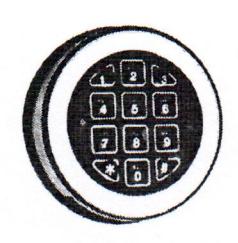
Base Line Key Pad

General
The lock operates with a numeric six-digit code or a word with 6 letters. Each key press is confirmed with an audio and LED signal.
After entry of a valid code a double signal follows. An invalid entry is followed by a long signal. After 10 seconds without entry, current code being entered will be cancelled.
Open
Enter code (factory code = 1-2-3-4-5-6), unlock door and open. If not opened within 3 seconds, the lock secures automatically. If code entry failed on first attempt wait 20 seconds before re-entering. Three long beeps indicate the lock bolt is jammed. Release the handle and re-enter the code.
Locking:
Close door and turn handle fully to closing position. The lock is secured. Verify locked status by trying to turn handle back.
Manipulation protection:
Entry of four consecutive invalid codes-keypad is blocked for 5 minutes. During this period, the LED flashes every 10 seconds and any key pressed causes a long signal. After expiration, entry of two more invalid codes, restarts the 5 minute blocking period.
Safety reference:
All codes are to be securely stored. Do not use personal date (i.e. Birthdays, telephone numbers etc.) as the code. Change the factory code before you start using the safe!
Change Code (With Safe Door OPEN)
Press and hold Key [0] until double signal. The light remains on during the following action.
- Enter old code (double signal)
- •Enter new code (double signal) and repeat new code (double signal) In case of entry errors (long signal), the old code remains valid.
Battery Low Warning and Battery Change
A series of signals indicates that the battery is weak and must be replaced. Use only 9V ALKALINE—batteries! The battery compartment is located at the bottom of the entry unit.
www.LpLOCKS.com
Base Line Single User Instructions © 2007 LpLOCKS, LLC