Locknetics WMG600 WMG1200 Electromagnetic Lock Installation Instructions 112117
Open the original PDF document
View PDFWMG600 & WMG1200 Series
Electromagnetic Lock Installation Instruction (Waterproof Series)
A Technical Specification
| Specification | UL1034 | UL294 | ||
|---|---|---|---|---|
| Operating Voltage | 12/24VDC | Rating | Performance Level | |
| Current Draw |
500mA/12VDC
250mA/24VDC |
Endurance: 100 000 evalor |
Destructive Attack: Level I
Line Security: Level I |
|
| Operating Temperature | -31° to +150.8°F (-35° to + 66°C) | WMG1200 | Static force: 1,000 lb |
Standby Power: Level I
Endurance: Level IV |
| Reed Switch Rating | 0.1A/20VDC (Resistive load) |
Dynamic force: 70 ft-lb
Endurance: 100,000 cycles |
||
| Holding Force | 600lbs & 1200lbs | UL Requirements | ||
| Lock Surface Temperature | ≦ Current temperature ± 20°C | OL Requilements | ||
| Lifetime Test | 100,000 cycles | UL 294 indoor use, UL 1034 indoor and outdoor use | ||
| Humidity | 0 to 85% Non-condensing |
|
||
| Finish |
Magnet Surface: Galvanized
Housing: Brushed stainless steel (US32D) |
|||
WARNING
Warnings indicate potentially hazardous conditions, which if not avoided or corrected, may cause death or serious injury.
A CAUTION
Cautions indicate potentially hazardous conditions, which if not avoided or corrected, may cause minor or moderate injury. Cautions may also warn against unsafe practices.
NOTICE
Notices indicate a condition that may cause equipment or property damage only.
Pre-Installation Considerations
- Use ONLY the hardware provided for mounting this product (NOTE: Non-standard Door thickness may require different sex nut hardware - see specific instructions for required hardware).
- Follow the installation procedure as described in this manual.
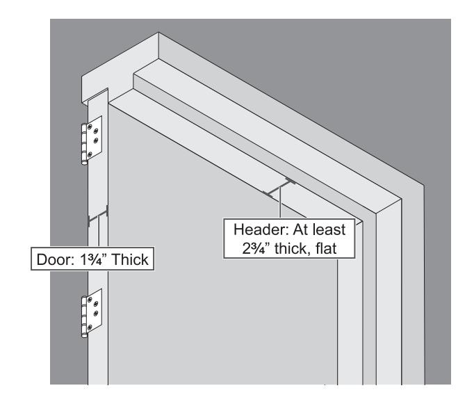
- Check door thickness. If the door is not 13/4" thick, a different sex nut will be required. Contact customer service at 1-877-671-7011.
- Check door header. A minimum 23/4" thick, flat surface is needed to securely mount all screws for the magnet. If you do not have the required surface, you will need filler plates and/or angle brackets to properly mount the magnet. Contact customer service at 1-877-671-7011.
Important Notes
CAUTION
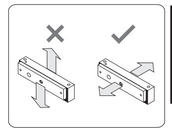
The electromagnet lock requires a face-to-face fitting as shown in Figure otherwise, the holding force will be greatly decreased (direction of hydraulic press pull must be collinear).
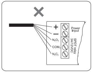
Do not apply power wires and signal wires in the same cable or conduit.
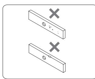
Make sure the contact area of the electromagnetic lock and the armature plate are clean or the bond sensor output function will not work.
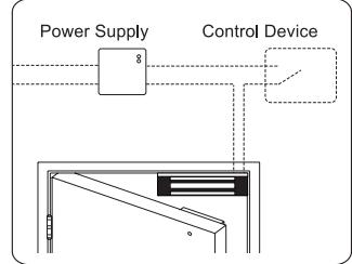
The electromagnet locks are fail-safe, therefore it may be required that the UPS remain locked during power failure.
CAUTION
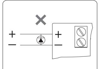
Remove any diode installed across the magnetic lock for spike suppression. The magnet is fitted with a metal oxide varistor to prevent back EMF.
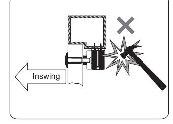
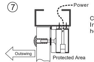
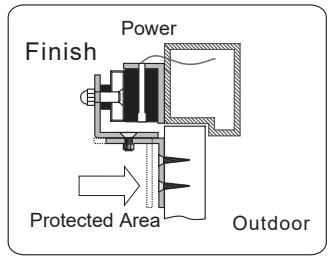
Be aware that it is better to install the electromagnet lock inside the house and hide the cable inside the door frame in order to guard against unlawful entry. With LZ for inswing doors.
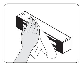
Wipe the surface of magnet lock with anti-rust oil regularly.
Optional Bracket
Brackets installation are according to door swing direction and door frame type, e.g. narrow frame door, frameless glass door, inswing door, etc.
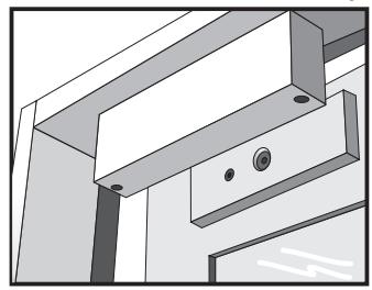
Regular Installation (outswing door)
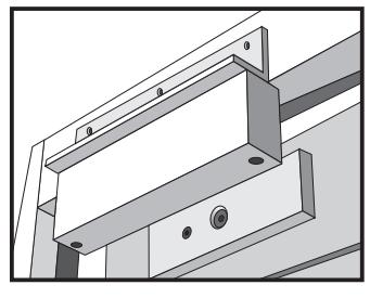
L-bracket for narrow frames (optional)
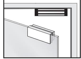
U-bracket for frameless glass doors (optional) WMG600 only outswing door.
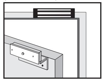
LZ-bracket for inswing doors (optional)
F
Regular Installation
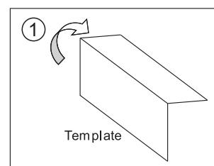
Fold the mounting template to form a 90 degree angle.
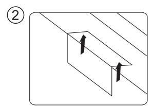
Place the template in the proper position on the door/frame and mark the hole positions.
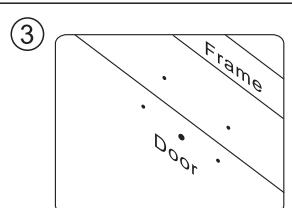
Drill the holes according to the marks.
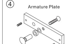
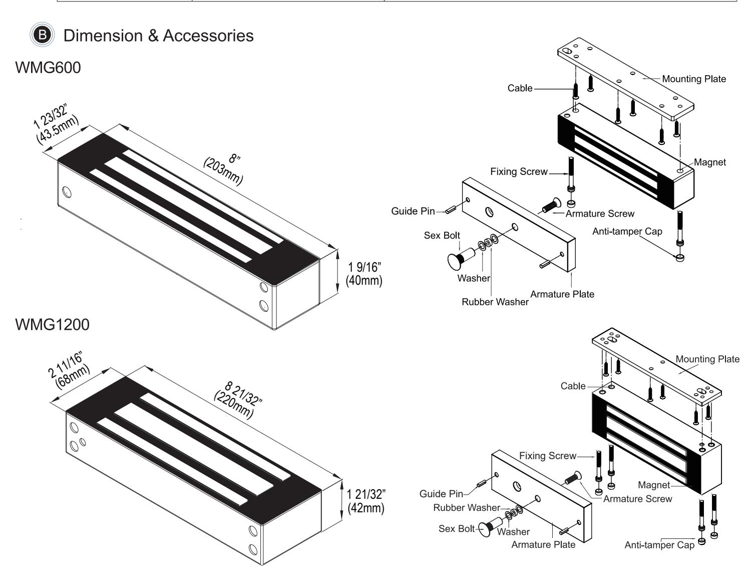
Please install the armature plate as illustrated here. (Dimensions of the holes are depending on the door types as illustrated below.)
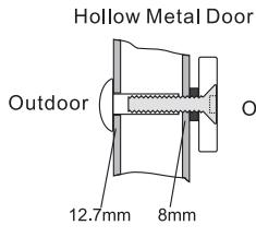
12.7mm 8mm 6.8m Drill a Ø8mm hole through door, on closing side enlarge to Ø12.7mm by a sexnut bolt on the opening side.
Outdoor O
Reinforced Door
Drill a Ø6.8mm hole and tap on closing side a M8x12.5 thread.
Outdoor 36mm ad 12.7mm 8mm
Solid Door
Drill a Ø8mm hole through door on closing side enlarge to Ø12.7mm, by a sexnut bolt on the opening side. The depth is 36mm.
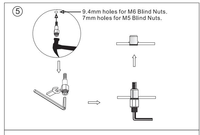
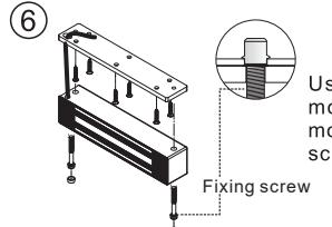
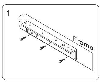
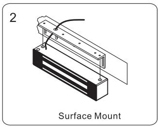
Use the screws to permanently mount the mounting plate, then mount the magnet with the fixing screws provided.
Connect the power and test the unit. Insert the anti-tamper caps into the holes of mounting screws.
LOCKNETICS.
LZ or Z Bracket for Inswing Doors
can still be closed.
magnet on L bracket.
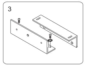
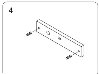
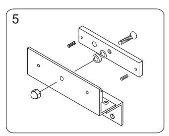
Attach the armature plate and washers to the Z bracket assembly.
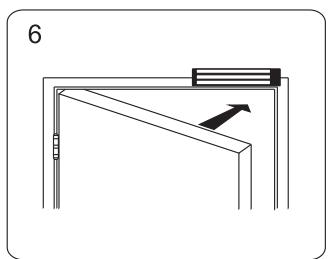
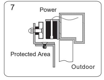
After the magnet attracts the armature plate, adjust the Z bracket to fit the door.

| Bond Sensor Output | ||
|---|---|---|
|
Parallel Connection:12VDC
Series Connection:24VDC Red Red White White Power Supply Power Supply Black Black Green Green Control Decive Control Decive N.C. Contact or Access Relay N.C. Contact or Access Relay Brown (N.C.) Brown (N.C.) Blue (COM.) Blue (COM.) Yllow (N.O.) Yllow (N.O.) |
lndicates locked and unlocked
status N.O Door locked N.C Door unlocked (Reed switch rated: 0.1A/20VDC) |
| Problem | Possible Cause | Solution |
|---|---|---|
|
Door does
not lock |
No power | Make sure the wires are connected properly Check that the power supply is connected and working properly Make sure the lock switch is wired correctly |
| Low holding force | Poor contact between electromagnet and armature plate | Check if the armature plate is deformed? Make sure if the rubber washer was used between magnet lock and armature plate. Make sure the contact surfaces of the electromagnet and armature plate are clean and free from dust and foreign material. |
| Low voltage or incorrect voltage setting | Ensure the electromagnet lock is set for the correct voltage. Check for proper voltage at the electromagnet locks input. If low determine if the correct wire gauge is being used to prevent excessive voltage drop. | |
|
Sensor output
is not functioning |
A secondary diode was installed across the electromagnet lock | Remove any diode installed across the magnet "spike" suppression. (The magnet is fitted with a metal oxide varistor to prevent back EMF) |
| Misalignment between the reed switch and electromagnet lock | Make sure the armature plate and electromagnet lock are aligned correctly. |
For details regarding the limited warranty:

1-877-671-7011 www.allegion.com/us

© Allegion 2018 47258719 Rev 01/18-c