Locknetics DKP 165 Digital Keypad Installation Instructions 112097
Open the original PDF document
View PDFDKP-165 / DKP-165-FM / DKP-165-S
USER'S MANUAL
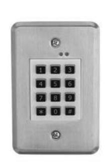
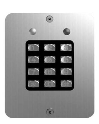
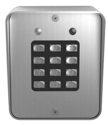
DKP-165 DKP-165-FM DKP-165-S
For details regarding the limited warranty:
Customer Service
1-877-671-7011 www.allegion.com/us

© Allegion 2018 47259492 Rev 01/18-b
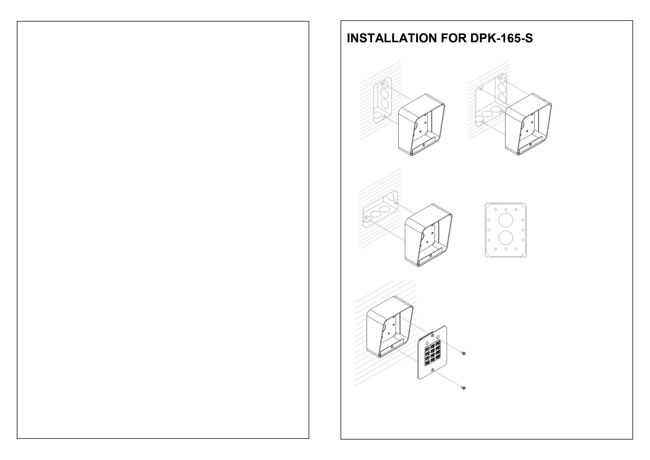
INSTALLATION FOR DKP-165
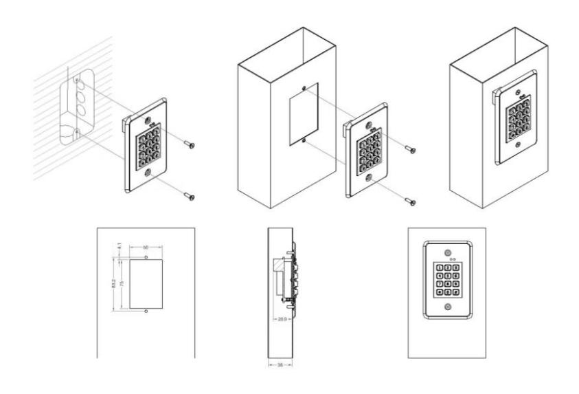
INSTALLATION FOR DKP-165-FM
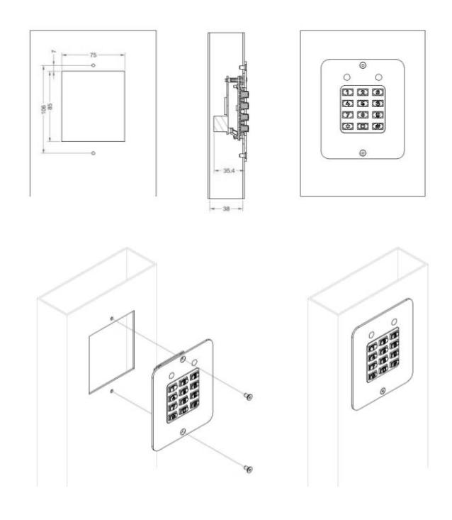
The DKP-165 Series is a digital, code-operated keypad for access control or for remote-control applications. Operating on 12/24VDC, the DKP-165 Series purpose is to keep unauthorized people off restricted premises, while permitting authorized people to enter. When any one of the correct codes is identified by the keypad, it energizes a relay which unlocks a door or performs any desired switching functions.
SPECIFICATIONS
|
Model
No |
DKP-165 | DKP-165-S | DKP-165-FM | ||||||
|---|---|---|---|---|---|---|---|---|---|
| Surface Mounted | Surface mounted | Surface mounted | Flush mounted | ||||||
|
Dimensions
H x W x D |
4 3/4" x 3" x 1 3/8"
(120 x 76 x 34.9mm) |
4 3/4" x 3 15/16" x 1 1/2"
(120 x 100 x 37.4mm) |
|||||||
|
Input
Voltage |
12V~24VDC | ||||||||
|
Operating
Current |
30
mA typical, 150 mA maximum |
||||||||
|
•
Relay #1, SPDT, 5 Amps @ 28VDC maximum |
|||||||||
|
•
Relay #2, SPDT, 1 Amp @ 28VDC maximum |
|||||||||
| Outputs |
•
Output #3 and #4, solid state open collectors, short to |
||||||||
|
common 100 mA
@24VDC maximum |
|||||||||
| Contact rating |
2A
30VAC/VDC |
||||||||
| Humidity | 5% to |
95%,
non-condensing |
|||||||
| Operating | |||||||||
| Temperature | -25°C~55°C | ||||||||
| Features | Operating Features | |
|---|---|---|
| • | Keypad programmable | System reset |
| • | 480 user codes | Entry code length, 1 to 6 digits |
| • | 1 to 6 digit user codes | Adding a new PIN |
| • | 4 independent outputs | Erasing a single PIN |
| 4 independent timers | Erasing all PINs | |
| • | 2 Form C relay contacts | Changing the master programming |
| • | 2 solid state open collector | code |
| outputs | On-time for each of the four | |
| • | Program entry codes to activate | outputs |
| one or two relays | Beep sounds on key presses | |
| • | Disable input | Beep sound during each of the |
| • | Door sense input | four outputs activation time |
| Request-to-exit/enter input | Keypad lockout after specified | |
| • | Keypad tamper lockout | number of incorrect PIN attempts, |
| • | Timed anti-passback | from 2 to 7 |
| (Prevents using same code again | Anti-passback time period from 1 | |
| before the programmed time | to 4 minutes or no anti-passback | |
| elapses) | protection | |
| Anti-tailgate | Anti-tailgate | |
| Two LED status indicators | Alarm shunt output | |
| (Green/Red and Yellow) | Forced entry output | |
| • | Tactile key feel |
|
| Audible code entry verification | Door sense/inhibit input | |
| • | 12 or 24V, DC operation | Keypad lockout output |
| Keypad active output | ||
| DKP-165 Series Basic Programming | |||||||||||||
|---|---|---|---|---|---|---|---|---|---|---|---|---|---|
| NO |
Programm
-ing Mode |
Default | Instruction | ||||||||||
| 24 |
Keypad
Lockout Count |
Press | 51 | # | Attempts (2 - 7) | # |
Seconds
(1 - 60) |
# | • Attempts=Number of attempts before lockout (2-7) • Seconds=(1-60) | 3,60 | Press: 51# Attempts # Seconds # Sets the number or incorrect entry code attempts allowed before the keypad "locks out" | ||
| Select Door | 52 | # |
INPUT
(0,1) |
# | Input=0 fo |
Door Sense
nhibit |
0 | Press: 52# Input # The input (gray wire) can be programmed for DOOR SENSE or INHIBIT. | |||||
| 25 |
Sense or
Inhibit Input |
When programmed for DOOR SENSE, if an open condition on the input occurs before access is granted (with an entry code or with the request-to-enter input) a FORCED ENTRY output will occur. If an open condition remains 60 seconds after a relay activation for access, a DOOR AJAR output will occur. When programmed for INHIBIT, a closed condition on the input will prevent Relay #1 from activating when access is requested with an entry code. This mode is typically used with an external timer to disable the access device at certain times. | |||||||||||
| 26 |
Anti-Pass
Back Time |
53 | # |
Minutes
(1 - 4) |
# |
Minutes=
0=No Ant |
Tin
i-p |
ne in minutes (1-4)
assback |
0 | Press: 53 # Minutes # Sets the length of time an entry code will not function after it is\nused. | |||
| 27 |
Keypad
light |
54 | # |
INPUT
(0 - 2) |
0 = alway
1 = norma 2 = alway |
al | 1 | • Press: 54 # INPUT # • INPUT= (0 - 2) | |||||
| DKP-165 Series Basic Programming | ||||||||||||
|---|---|---|---|---|---|---|---|---|---|---|---|---|
| NO | Programm -ing Mode | Press | I | Ρ | rogramming | g C | Default | Instruction | ||||
| 16 |
Auxiliary
Relay On-time |
Fiess | 32 | # |
Seconds
(0 - 60) |
Seconds=Output
time in seconds (0-60) |
5 | Press: 32# Seconds # Sets the length of time the Auxiliary Relay activates when triggered. | ||||
| 17 |
Solid-state
Output #3 On-time |
33 | # |
Seconds
(0 - 60) |
# |
Seconds=Output
time in seconds (0-60) |
5 | Press: 33# Seconds # Sets the length of time Output #3 activates when triggered. | ||||
| 18 |
Solid-state
Output #4 On-time |
34 | # |
Seconds
(0 - 60) |
# |
Seconds=Output
time in seconds (0-60) |
5 | Press: 34# Seconds # Sets the length of time Output #4 activates when triggered. | ||||
| 19 |
Beep Sounds
on Keystrokes |
40 | # |
Sound
(0 , 1) |
# |
Sound=1 for Yes
Sound=0 for No |
1 |
|
||||
| 20 |
Beep Sounds
During Main Relay |
41 | # |
Sound
(0 , 1) |
# |
Sound=1 for Yes
Sound=0 for No |
0 | Press: 41# Sound # Selects whether or not the keypad beeps during Main Relay activation. | ||||
| 21 |
Beep Sounds
During Auxiliary Relay |
42 | # |
Sound
(0 , 1) |
# |
Sound=1 for Yes
Sound=0 for No |
0 |
|
||||
| 22 |
Beep Sounds
During Output #3 |
43 | # |
Sound
(0 , 1) |
# |
Sound=1 for Yes
Sound=0 for No |
0 |
|
||||
| 23 |
Beep Sounds
During Output #4 |
44 | # |
Sound
(0 , 1) |
# |
Sound=1 for Yes
Sound=0 for No |
0 | Press: 44# Sound # Selects whether or not the keypad beeps during Output #4 activation. | ||||
Entry codes:
- 1) Up to 480 user entry codes
- 2) 1 to 6 digits user codes
- 3) can be programmed
- 4) Keypad users request access by entering their code
- 5) Users of the SDC have up to 40 seconds to key in their entry code
- 6) Up to eight seconds are allowed between each keystroke
- 7) All digits of the entry code must be entered. Example: if the code is 0042, the user must enter "0 0 4 2".
- 8) If the wrong key is pressed, pressing the * key will reset the keypad
- 9) After a correct code is entered, the red indicator will turn green and the programmed relay will activate for the programmed time
- 10) If the number of incorrect codes entered exceeds the keypad lockout count, the yellow indicator will light, indicating that the keypad is locked out.
- 11) The lockout will remain for one minute
- 12) After a valid code has been entered, it will be unusable until the anti-pass back time expires.
- 13) They can activate either, or both of the relay outputs
- 14) The EEPROM memory retains all entry codes and programming, even without power.
- 15) An internal jumper is provided to reset the master code
Indicators (LEDs):
- 1) The left indicator lights red to indicate power
- 2) The left indicator turns green when access is granted
- 3) The right indicator lights yellow when the keypad is in "lockout" condition (from too many incorrect code entries)
Internal sounder:
- 1) An internal sounder beeps when each key is pressed
- 2) An internal jumper sets the sounder volume high or low
The Door SENSE / Inhibit input
- 1) SENSE terminal (gray wire) can be programmed for either a door sense or inhibit input. Both features cannot be used at the same time.
- 2) If programmed for "door sense" the input is wired to a normally closed switch on the door to detect when the door is opened or closed. Forced entry or door ajar situations can then be detected.
- Route two wires from the switch to the keypad box. Connect the door switch to the keypad's SENSE terminal (gray wire E8) and COM terminal (any black wire)
- 4) Using door sense, the "Auto-relock" feature will prevent "tailgating" by turning off the Main Relay output immediately when the door is closed after access has been granted.
- 5) If it is programmed for "inhibit", the input can be wired to a "service" switch or automatic timer that will disable the Main Relay when required.
- 6) Route two wires from the switch or timer to the keypad box. Connect the inhibit switch/timer normally open terminals to the keypad's SENSE (gray wire E8) and COM (black wires) terminal.
| DKP-165 Series Basic Programming | |||||||||||||
|---|---|---|---|---|---|---|---|---|---|---|---|---|---|
| NO | Programm -ing Mode | Press | Р | rogramm |
g Code
ode |
Default | Instruction | ||||||
| 9 |
Select
Request-to- Exit Output |
. 1000 | 21 | # |
OUTPUT
(0 - 4) |
Output 1=Main Relay 2=Auxiliary Relay 3=Output #3 4=Output #4 0=No Output) | 1 | Press: 21# Output # Output=Output to Activate(0 Sets which output activates when the Request-to-Exit input is grounded. This output may be timed or toggled | |||||
| 10 |
Select
Forced Entry Output |
22 | # |
OUTPUT
(0 - 4) |
# | Output 1=Main Relay 2=Auxiliary Relay 3=Output #3 4=Output #4 0=No Output) | 0 | Press: 22# Output # Output=Output to Activate(0 Sets which output activates if the DOOR SE NSE input opens before access is granted. This output is not timed. | |||||
| 11 |
Select Door
Ajar Output |
23 | # |
OUTPUT
(0 - 4) |
# |
Output
1=Main Relay 2=Auxiliary Relay 3=Output #3 4=Output #4 0=No Output) |
0 | Press: 23# Output # Output=Output to Activate(0-4) Sets which output activates if the DOOR SENSE input stays open 60 seconds after access is granted. This output is not timed | |||||
| 12 |
Select
Keypad Lockout Output |
24 | # |
OUTPUT
(0 - 4) |
# | Output 1=Main Relay 2=Auxiliary Relay 3=Output #3 4=Output #4 0=No Output) | 0 | Press: 24# Output # Output=Output to Activate(0-4) Sets which output activates when the keypad is "locked out" after too many incorrect entry code attempts. The lockout time is 60 seconds. | |||||
| 13 |
Select
Keypad Active Output |
25 | # |
OUTPUT
(0 - 4) |
# | Output 1=Main Relay 2=Auxiliary Relay 3=Output #3 4=Output #4 0=No Output) | 0 | Press: 25# Output # Output=Output to Activate(0-4) Sets which output activates when any keys are pressed. This output is timed. If toggle mode is selected for the output, the timer value defaults to 2 seconds. | |||||
| 14 |
Select
Alarm Shunt Output |
26 | # |
OUTPUT
(0 - 4) |
# |
Output
1=Main Relay 2=Auxiliary Relay 3=Output #3 4=Output #4 0=No Output) |
0 | Press: 26# Output # Output=Output to Activate(0-4) Sets which output activates during the time access is granted. (Use this output ot shunt alarm contacts attached to the access door.) This output may be timed or toggled. | |||||
| 15 |
Main Relay
On-time |
31 | # |
Seconds
(0 - 60) |
# |
Seconds=Output
time in seconds (0-60) |
5 | Press: 31# Seconds # Sets the length of time the Main Relay activates when triggered. | |||||
| DKP-165 Series Basic Programming | ||||||||||||
|---|---|---|---|---|---|---|---|---|---|---|---|---|
| Programm | Programming Code | |||||||||||
| NO | -ing Mode |
Press
Code |
Default | Instruction | ||||||||
| 6 |
Adding
a New Entry Code |
12 | # |
user
code (1 - 6 digits) |
# |
user
code (Repeat) |
# |
OUTPUT
(a b c d) 1000=Main Relay 0100=Auxiliary Relay 0010=#3 OUTPUT 0001=#4 OUTPUT 1100=Both Relays 1110=Both Relays & #3 1111=ALL OUTPUT |
# |
4
digits |
•
Press: 12 # Code # Code # OUTPUT # • Code=The new entry code: 1-999999, depending on code length • OUTPUT =Relay output entry code will activate |
|
| 7 |
Erasing
a Single Entry Code |
13 | # |
user
code (4 - 6 digits) |
# |
user
code (Repeat) |
# |
4
digits |
•
Press: 13 # Code # Code # • Code=the entry code to delete • The yellow indicator will flash quickly while its memory for the code to erase. The green indicator will light when the code is deleted. |
|||
| 8 |
Erasing
All Entry Codes |
14 | # |
00000
0 |
# | 000000 | # |
•
Press: 14# 000000 #000000# • Performing this command will remove all entry codes from the memor y • The green indicator will light while the memory is being deleted. This may take up to 15 seconds. |
||||
The REQUEST-TO-EXIT input
- 1) The input can be wired to a pushbutton to provide codeless activation of Main Relay, Auxiliary Relay, Output #3 or Output #4 (programmable).
- 2) Route two wires from the keypad box to a normally open pushbutton mounted on the secure side of the door. Connect the wires to the pushbutton and to the keypad's EXIT (violet wire E6) and COM (black wires) terminals.
The ALARM SHUNT output
- 1) The output activates when access is granted.
- 2) It can be wired to shunt alarm contacts on the access door/gate to prevent triggering of an alarm when authorized access occurs.
Relay / solid state outputs
- 1) 4 independent outputs
- 2) 4 independent timers
- 3) 2 Form C relay contacts
- 4) The Main Relay has a 5 Amp capacity
- 5) The Auxiliary Relay has a 1 Amp capacity
- 6) Program entry codes to activate one or two relays
- 7) 2 solid state open collector outputs
- 8) Two solid state outputs, capable of switching 100 mA to common, are programmable to signal forced entry, door ajar, lockout, alarm circuit shunting, request-to-exit, and keypad active conditions.
- 9) The two solid state outputs can be used to activate indicators or sounders.
Door Strike Wiring
- 1) Install a low voltage electric door strike for unlocking the door
- 2) Route two wires between the door strike and the keypad box
- Connect one of the door strike wires to the keypad's MAIN RELAY N.O. terminal (TB1 #3)
- 4) Connect the other door strike wire to the keypad's AC/DC+ terminal (TB #1)
- 5) Connect a wire between the keypad's AC/DC- terminal (TB #2) and the MAIN RELAY COM terminal (TB #4)
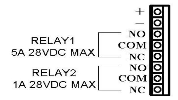
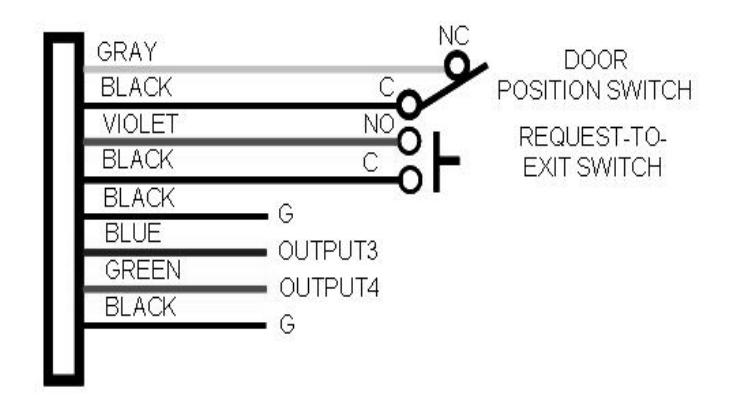
Basic Door Installation Wiring
BASIC PROGRAMMING
- When in Programming Mode, both indicators will turn off until programming begins
- 2) After a programming option number is entered, the yellow indicator will blink. This shows that it is ready to accept the new programming data.
- 3) After the new data entry is complete, the yellow indicator will flash while the data is being stored. The green indicator will light if the data is accepted. The red indicator will light if any programming data is entered incorrectly, and the command will have to be fully re-entered.
DKP-165 Series Basic Programming
Programming Code
| NO | Mode | Press | P | ro |
gramming C
Code |
de | Default | Instruction | ||
|---|---|---|---|---|---|---|---|---|---|---|
| 1 |
Enter
Programming |
#9# | MASTER ( | CC | DE | 123456 | Press: # 9 # Master Code (Default 123456) It is used to enter Programming Mode. | |||
| 2 |
Exit
Programming |
**# | Press: * * # The red indicator will light after exiting Programming Mode | |||||||
| 3 |
Re-entering a
Command after a Mistake |
*9# |
|
|||||||
| 4 |
Changing the
6-Digit Master Programming Code |
10 | # |
MASTER
CODE (6 digits) |
# |
MASTER
CODE (NEW) |
# | 123456 | Press: 10# Master Code# Master Code# Master Code=The new 6 digit Master Programming Code It is used to change Master Programming code | |
| 5 |
Setting Entry
Code Length |
11 | # |
Length
(1 - 6) |
# | 4 digits | Press: 11 # Length # Length: 1-6 for entry code length If the Entry Code Length is going to be changed from the factory default of 4 digits, make this change first before programming any entry codes. |