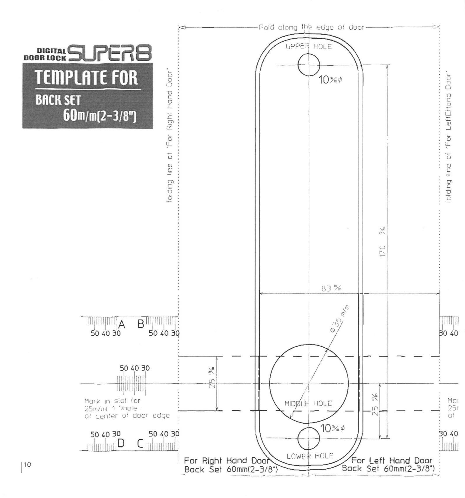
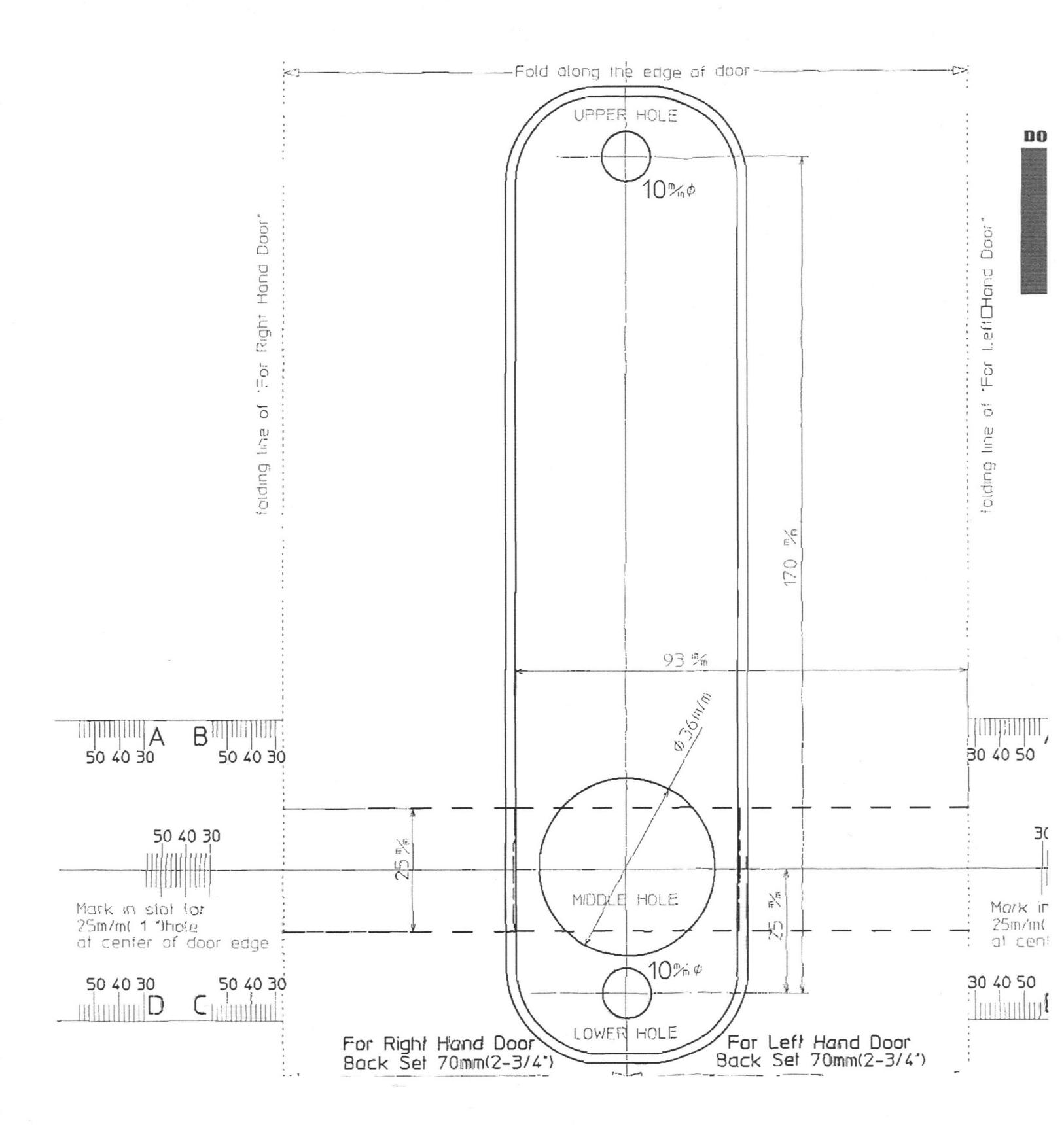
LockeyUSA 7055 Mechanical Digital Door Lock Instructions Template 1
Open the original PDF document
View PDFDIGITAL DOOR LOCK SUPERIOR SUPERIOR SUPERIOR SUPERIOR SUPERIOR SUPERIOR SUPERIOR SUPERIOR SUPERIOR SUPERIOR SUPERIOR SUPERIOR SUPERIOR SUPERIOR SUPERIOR SUPERIOR SUPERIOR SUPERIOR SUPERIOR SUPERIOR SUPERIOR SUPERIOR SUPERIOR SUPERIOR SUPERIOR SUPERIOR SUPERIOR SUPERIOR SUPERIOR SUPERIOR SUPERIOR SUPERIOR SUPERIOR SUPERIOR SUPERIOR SUPERIOR SUPERIOR SUPERIOR SUPERIOR SUPERIOR SUPERIOR SUPERIOR SUPERIOR SUPERIOR SUPERIOR SUPERIOR SUPERIOR SUPERIOR SUPERIOR SUPERIOR SUPERIOR SUPERIOR SUPERIOR SUPERIOR SUPERIOR SUPERIOR SUPERIOR SUPERIOR SUPERIOR SUPERIOR SUPERIOR SUPERIOR SUPERIOR SUPERIOR SUPERIOR SUPERIOR SUPERIOR SUPERIOR SUPERIOR SUPERIOR SUPERIOR SUPERIOR SUPERIOR SUPERIOR SUPERIOR SUPERIOR SUPERIOR SUPERIOR SUPERIOR SUPERIOR SUPERIOR SUPERIOR SUPERIOR SUPERIOR SUPERIOR SUPERIOR SUPERIOR SUPERIOR SUPERIOR SUPERIOR SUPERIOR SUPERIOR SUPERIOR SUPERIOR SUPERIOR SUPERIOR SUPERIOR SUPERIOR SUPERIOR SUPERIOR SUPERIOR SUPERIOR SUPERIOR SUPERIOR SUPERIOR SUPERIOR SUPERIOR SUPERIOR SUPERIOR SUPERIOR SUPERIOR SUPERIOR SUPERIOR SUPERIOR SUPERIOR SUPERIOR SUPERIOR SUPERIOR SUPERIOR SUPERIOR SUPERIOR SUPERIOR SUPERIOR SUPERIOR SUPERIOR SUPERIOR SUPERIOR SUPERIOR SUPERIOR SUPERIOR SUPERIOR SUPERIOR SUPERIOR SUPERIOR SUPERIOR SUPERIOR SUPERIOR SUPERIOR SUPERIOR SUPERIOR SUPERIOR SUPERIOR SUPERIOR SUPERIOR SUPERIOR SUPERIOR SUPERIOR SUPERIOR SUPERIOR SUPERIOR SUPERIOR SUPERIOR SUPERIOR SUPERIOR SUPERIOR SUPERIOR SUPERIOR SUPERIOR SUPERIOR SUPERIOR SUPERIOR SUPERIOR SUPERIOR SUPERIOR SUPERIOR SUPERIOR SUPERIOR SUPERIOR SUPERIOR SUPERIOR SUPERIOR SUPERIOR SUPERIOR SUPERIOR SUPERIOR SUPERIOR SUPERIOR SUPERIOR SUPERIOR SUPERIOR SUPERIOR SUPERIOR SUPERIOR SUPERIOR SUPERIOR SUPERIOR SUPERIOR SUPERIOR SUPERIOR SUPERIOR SUPERIOR SUPERIOR SUPERIOR SUPERIOR SUPERIOR SUPERIOR SUPERIOR SUPERIOR SUPERIOR SUPERIOR SUPERIOR SUPERIOR SUPERIOR SUPERIOR SUPERIOR SUPERIOR SUPERIOR SUPERIOR SUPERIOR SUPERIOR SUPERIOR SUPERIOR SUPERIOR SUPERIOR SUPERIOR SUPERIOR SUPERIOR SUPERIOR SUPERIOR SUPERIOR SUPERIOR SUPERIOR SUPERIOR SUPERIOR SUPERIOR SUP
1
MECHANICAL COMBINATION ACCESS CONTROL DOOR LOCK EQUIPPED WITH 'DOUBLE PUSHING' AND 'SINGLE PUSHING' FUNCTION
INSTALLATION INSTRUCTIONS
MISHDE BODY
CONTENTS
- PAGE 1 THE NAME AND DETAILS OF THE ENCLOSED PARTS
- PAGE 3 BEFORE INSTALLATION
- PAGE 4 HOW TO INSTALL
- PAGE 7 HOW TO USE
- PAGE 8 HOW TO CHANGE THE CODE NUMBER
- PAGE 10/11 TEMPLATE
** READ ALL THE INSTRUCTIONS BEFORE THE INSTALLATION
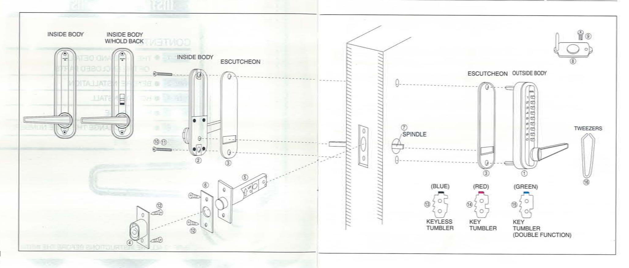
THE NAME AND DETAILS OF THE ENCLOSED PARTS
| NO. | NAME OF PARTS | |
|---|---|---|
| 1. | OUTSIDE BODY | 1PCE |
| 2. | INSIDE BODY | 1 |
| 3. | ESCUTCHEON | 2 |
| 4. | MAGNETIC MORTISE STRIKE | 1 |
| 5. | MAGNETIC LATCHBOLT UNIT (60MM BS OR 70MM BS) | 1 |
| 6. | FACE PLATE FOR LATCHBOLT | 1 |
| 7. | SPINDLE (87MM L) | 1 |
| 8. | L SUPPORT PIN | 1 |
| 9. | MACHINE SCREW 4×6 FOR L SUPPORT PIN | 1 |
| NO. | NAME OF PARTS | |
|---|---|---|
| 10. | MACHINE SCREW 4×55 | 2PCS |
| 11. | MACHINE SCREW 4×45 | 2 |
| 12. | WOOD SCREW 4×16 | 4 |
| 13. | KEYLESS TUMBLER(BLUE) | 1 |
| 14. | KEY TUMBLER(RED) | 1 |
| 15. | DOUBLE FUNCTION KEY TUMBLER (GREEN) | 1 |
| 16. | TWEEZERS | 1 |
| 17. | CODE NUMBER CARD | 1 |
| 18. | INSTALLATION INSTRUCTIONS | 1 |

CONFIRM THE HAND OF OPENING
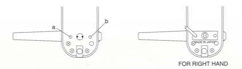
The lock comes factory set for right hand opening, if your door is hinged on the right from the entry side then proceed to HOW TO INSTALL after installing the L support pin as per below. If your door is hinge on the left from the entry side then follow changing the hand of opening to left hand.
CHANGING THE HAND OF OPENING TO LEFT HAND
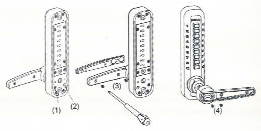
- Move the screw (1) into position (2)
- Remove the two screws (3) from the inside of the handle releasing the handle cover.
- Remove the two screws (4) that connect the handle to the lock, lift the handle off and reverse it to left hand. Replace all screws securely.
- Repeat the same with the inside handle.
- On the entry side of the lock either side of the spindle cog there are two holes(a,b), screw the L support pin into the following position for R/H opening and the opposite position for L/H opening.
HOW TO INSTALL THE DIGITAL DOOR LOCK, "SUPER-8"
Using the template provided on page 10 for 60m/m B.S. or 11 for 70m/m B.S., decide on the position you want your lock.
- Mark the hole centers for each of the 3 holes on the surface of the door, and for the latch bolt at the center of door edge through the template.
- Drill the 3 holes, the upper and lower 2 holes@10mm dia and 3rd larger hole @36mm dia.) the hole in the edge of the door @25mm dia for the latch bolt.
••• "60MM BACK SET" is 85mm depth ••• ••• "70MM BACK SET" is 95mm depth •••
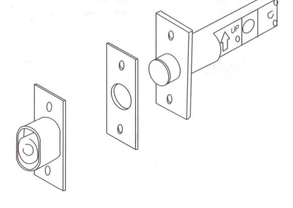
Insert the latch bolt into the slot making sure the arrow faces upwards and scribe a line around the latch-bolt face. Remove it.
Chisel out the scribed space until the latch bolt face is flush with the surface of the door edge.
Fasten latch bolt unit with the wood screws(4×16), evenly.
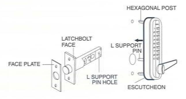
Insert the 2 hexagonal posts into the upper and lower holes of the front body and place the escutcheon on. Position the front body onto the door.
NOTE-CONFIRM THAT THE SUPPORT PIN IS INSERTED INTO THE SUPPORT PIN HOLE OF THE LATCHBOLT UNIT, SMOOTHLY.
CONT' HOW TO INSTALL THE DIGITAL DOOR LOCK, "SUPER-8"
Befor closing the door test your lock from the inside and out side to ensure it is set correctly.
AFTER CONFIRMING THE ABOVE
Close the door and decide on the position where the latch bolt head touches the face of the door jamb. And mark the hole for the mortise strike. After that, chisel out the space for the magnetic strike box. Fasten them with the wood screws.

HOW TO USE THE DIGITAL DOOR LOCK, "SUPER-8"
- 1. When the door is closed, the "SUPER-8" locks automatically.
- 2. From the inside, unlock using the lever handle.
- 3. From the outside,unlock by pressing the correct code and then using the lever handle.
"HOLDBACK" DEVICE
The holdback holds the latch bolt head back; this is very convenient. When using the code is not always necessary.
TO OPERATE
Pull the inside handle down until the latch bolt head retracts fully, and push the holdback down.
To restore push up the holdback.
TO PREVENT ANY PROBLEMS OR DAMAGE, READ THE FOLLWING INSTRUCTIONS BEFORE CHANGING YOUR CODE
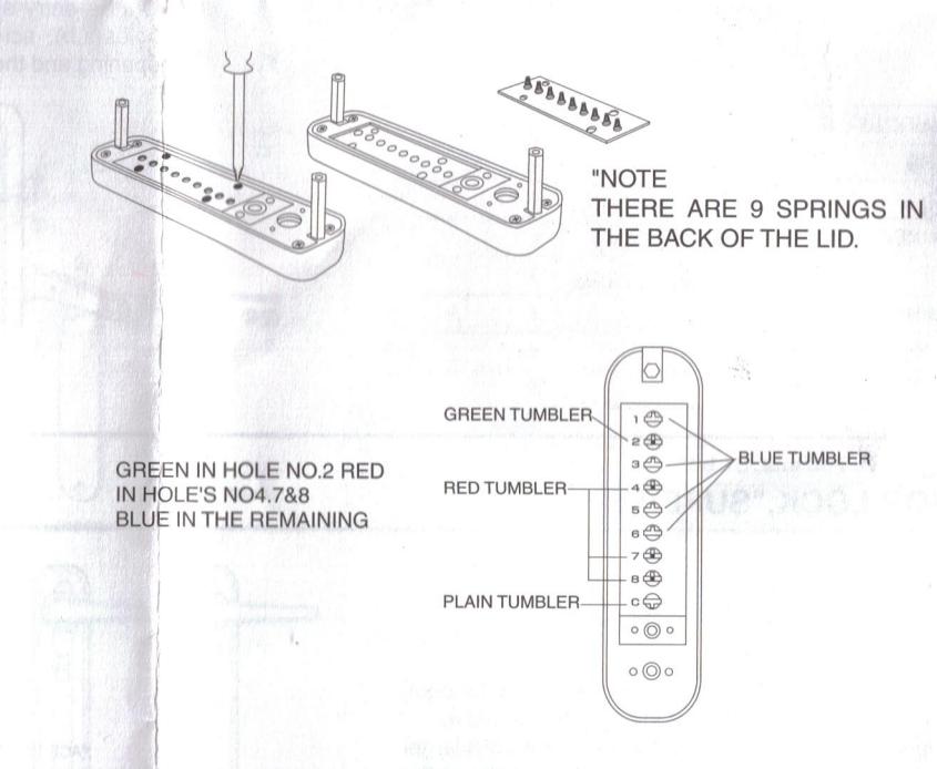
Hold the front lock body in the horizontal position. Remove the 4 red screws and take the lid off carefully.
Marie Carlotte Committee of the Marie Committee of the Committee of the Committee of the Committee of the Committee of the Committee of the Committee of the Committee of the Committee of the Committee of the Committee of the Committee of the Committee of the Committee of the Committee of the Committee of the Committee of the Committee of the Committee of the Committee of the Committee of the Committee of the Committee of the Committee of the Committee of the Committee of the Committee of the Committee of the Committee of the Committee of the Committee of the Committee of the Committee of the Committee of the Committee of the Committee of the Committee of the Committee of the Committee of the Committee of the Committee of the Committee of the Committee of the Committee of the Committee of the Committee of the Committee of the Committee of the Committee of the Committee of the Committee of the Committee of the Committee of the Committee of the Committee of the Committee of the Committee of the Committee of the Committee of the Committee of the Committee of the Committee of the Committee of the Committee of the Committee of the Committee of the Committee of the Committee of the Committee of the Committee of the Committee of the Committee of the Committee of the Committee of the Committee of the Committee of the Committee of the Committee of the Committee of the Committee of the Committee of the Committee of the Committee of the Committee of the Committee of the Committee of the Committee of the Committee of the Committee of the Committee of the Committee of the Committee of the Committee of the Committee of the Committee of the Committee of the Committee of the Committee of the Committee of the Committee of the Committee of the Committee of the Committee of the Committee of the Committee of the Committee of the Committee of the Committee of the Committee of the Committee of the Committee of the Committee of the Committee of the Committee of the Committee of the Committee of the Committee of the Committee of the Co
THE CODE TUMBLER
THE GREEN COLOURED ARE THE TUMBLERS FOR 'DOUBLE PUSHING' THE RED COLOURED ARE THE TUMBLERS FOR 'SINGLE PUSHING' THE BLUE COLOURED ARE KEYLESS TUMBLERS 'NON-CODE' THE PLAIN TUMBLER IS THE 'C' BUTTON (TO CLEAR) NEVER REMOVE THIS TUMBLER
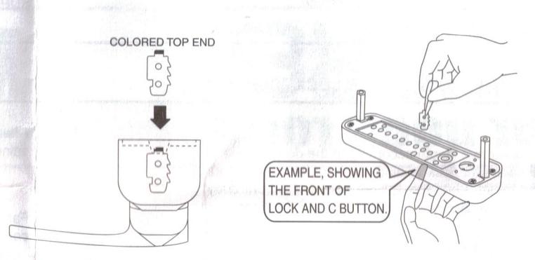
FOR EXAMPLE THIS "CODE NUMBER" IS MADE UP OF THE "C" TO CLEAR THEN 22478 WHILST PUSHING IN THE 'C' BUTTON, AND USING THE TWEEZERS
PROVIDED, PLACE YOUR CODE TUMBLERS INTO POSITION
V HOW TO CHANGE THE CODE NUMBER
TO INCREASE AND DECREASE THE NUMBER OF DIGITS USED IN YOUR CODE ADD MORE RED AND GREEN TO INCREASE, ADD MORE BLUE TO DECREASE.
IT IS VERY IMPORTANT TO REPLACE THE CODE TUMBLERS IN THE CORRECT WAY. THE COLORED TOP END MUST ALWAYS FACE UPWARDS.
AND THE SIDE OF THE TUMBLER THAT HAS THE RAISED NOTCHES MUST FACE TOWARD THE TOP OF THE LOCK.
REMEMBER TO KEEP THE 'C' PRESSED IN WHILE REMOVING AND REPLACEING THE TUMBLERS.
REPLACE THE PLATE CAREFULLY AND NOW TEST YOUR CODE BEFORE REPLACING IT ON THE DOOR.