LockeyUSA 2930 2945 Narrow Stile Mechanical Lock Instructions Template Compressed 1
Open the original PDF document
View PDF

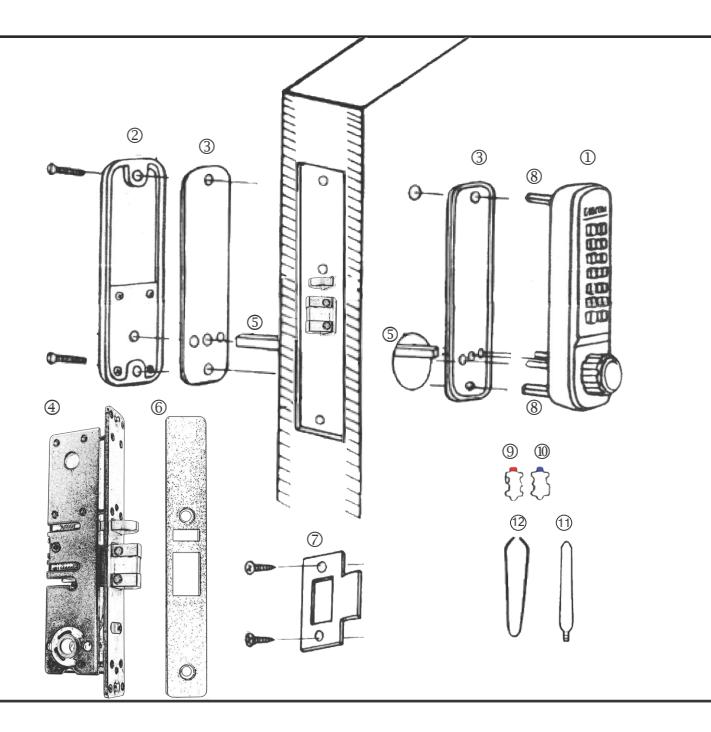
2930 & 2945 NARROW STILE INSTALLATION INSTRUCTIONS
| No. | Part Name | # included |
|---|---|---|
| 1 | Outside Body | 1 |
| 2 | Inside Body | 1 |
| 3 | Rubber Trim Plates | 2 |
| 4 | Narrow Stile Deadlatch | 1 |
| 5 | Spindle (30-45mm & 40-55mm) | 2 |
| 6 | Latch Face Plate | 1 |
| 7 | Strike Plate | 1 |
| 8 | Hex Bolts | 2 |
| 9 | Extra Code Tumblers (Red) | 2 |
| 10 | Extra Non-Code Tumblers (Blue) | 4 |
| 11 | Support Pin | 2 |
| 12 | Tweezers | 1 |
| 13 | Screw Kit | 1 |
IMPORTANT INFORMATION ABOUT YOUR 2930/2945
- 1. The Lockey 2930 & 2945 are designed for narrow stile prep doors or for configurations with existing narrow stile hardware with prep. The 2930 & 2945 can also be installed on new mortise prep doors, 2''x2'' gates or chainlink gates.
- 2. The drive/spindle hole is located on the bottom of the latch. The system operates opposite compared to Adams-Rite style products. The strike may need to be modified.
- 3. When the door is closed, the system locks automatically.
- 4. From the inside, unlock using the thumb turn/lever handle.
- From the outside, unlock by pressing 'C' (CLEAR), followed by your User Code.
Step 1: Change User Code/Combination (OPTIONAL)
To change user code/combination, see instructions on reverse side.
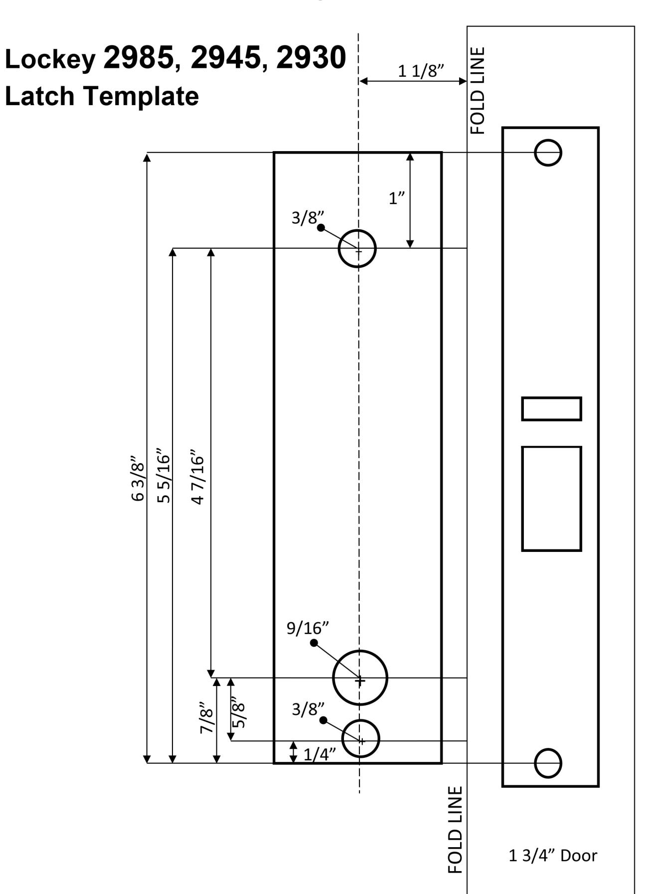
Step 2: Prep Door for Installation with Template
Place template (supplied) on door and fold along door's edge. Check to ensure proper measurements. Drill holes accordingly.
Step 3: Identify Door Handing
Right-Hand Doors – From exterior of door, hinges are on right side (Fig. 1). Left-Hand Doors – From exterior of door, hinges are on left side (Fig. 2).
The 2930 & 2945 are factory pre-handed for right-hand doors.
To change handing, remove two blue screws and cover plate from Outside Body. Move the pin from the right side of the Outside Body to the hole on the left side. Replace plate and screws.
Note: For 2930 DC (Double Combination), Inside Body handing must be opposite from Outside Body. Install at least one Support Pin (#11) in position 'A'/position 'B' on the Outside Body as shown in Fig. 3. Now, install/screw Hex Bolts (#8) into the top and bottom of the Outside Body as shown in Fig. 3.
Fig. 1 Fig. 2 Fig. 3 RIGHT HAND HINGE M Outside Body. as shown in Fig. 3.
Step 4: Change Latch Handing (if necessary) & Install Latch
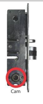
IMPORTANT: Do NOT remove Cam from latch when changing handing. Cam Position: MUST be on LEFT side of latch.
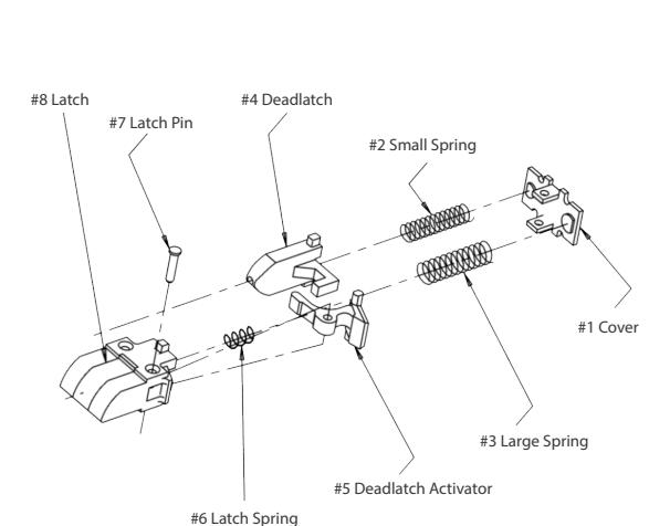
If latch does not pull and twist, proceed with the following steps:
- 1. Remove screws from both sides of latch casing.
- 2. Remove cover and interior springs (#1, #2, #3).
- 3. Remove latch and deadlatch (#4, #8).
- 4. Carefully remove Latch Pin (#7) and Latch Spring (#6).
- 5. Replace the Latch Spring (#6) and then move the Deadlatch Activator (#5) to the opposite side of the latch, ensuring that it depresses the Latch Spring.
- 6. Replace the Latch Pin.
- 7. Replace Latch, Deadlatch, Latching Springs and Cover.
- 8. Secure Screws on each side of the Latch Casing.
Place the Narrow Stile Deadlatch (#4) in the door prep and secure.

2930 & 2945 Narrow Stile Installation Instructions Continued...
Step 5: Verify Correct Spindle Length
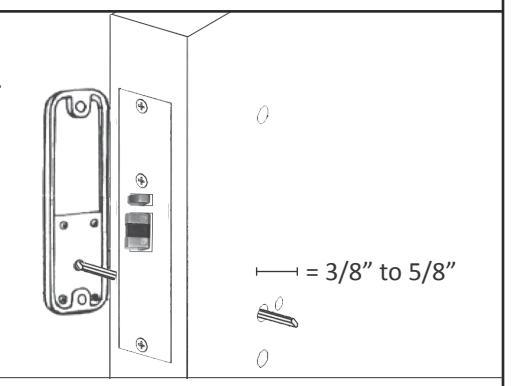
With the Deadlatch installed, hold the Inside Body (#2) and Rubber Trim Plate (#3) to the door. Place Spindle (#5) through Latch, into the Inside Body, as far as possible.
Spindle should extend from exterior of door 3/8" min. to 5/8" max.
If Spindle is too long, cut it to the correct length using pliers.
*IMPORTANT:
If spindle extends less than 3/8" it may not engage the lock. If spindle extends more than 5/8", it will cause the lock to bind.
Step 6: Complete Installation
Place the Rubber Trim Plate (#3) on the backside of the Outside Body (#1).
Place the Outside Body on the door.
The Hex Bolts (#8) should extend into the top and bottom holes.
The Support Pin (#11) should extend through the hole in the Latch (#4).
Insert the Spindle (#5) into the Outside Body (#1) ensuring it's in the proper angled position.
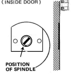
*IMPORTANT: SPINDLE POSITION/ANGLE
RIGHT-HAND DOORS: From inside, place spindle through Latch, into the Outside Body in the 2:00/8:00 position (above). LEFT-HAND DOORS: From inside, place spindle through Latch, into the Outside Body in the 10:00/4:00 position (below).
Place the Rubber Trim Plate (#3) and Inside Body (#2) on the inside of the door.
Using a screwdriver, secure the lock to the door (screw length dependent on door thickness).
Test the operation of the latch by turning the inside thumbturn.
Locate position where latch strikes door frame and install Strike Plate (#7).
TEST YOUR LOCK: Press 'C' button (clear), followed by your combination. Turn knob and lock will open.
After installing and testing the lock, secure Faceplate (#6).
Note: If latch sticks, first make sure Support Pin is in place. Second, verify correct spindle length (see step 5).
How to Change User Code/Combination SAVE
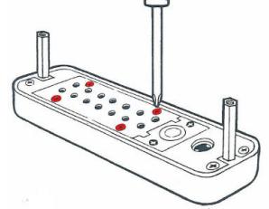
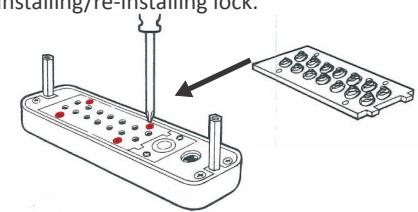
1. Using a #2 screwdriver, remove the four (4) Red Screws.
2. Carefully remove cover plate.
WARNING: Springs are attached to plate.
'C' = CLEAR (DO NOT REMOVE)
'Y' = PASSAGE ('Y' Tumbler may be removed to disable PASSAGE FUNCTION)
3. PRESS & HOLD 'C' BUTTON to release tumblers.
IMPORTANT: 'C' button MUST be pressed and held down when removing and inserting tumblers. Failure to do so will damage
the lock and void the warranty.
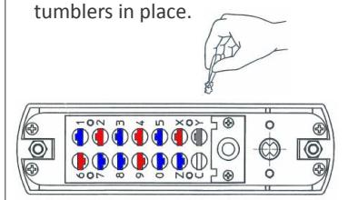
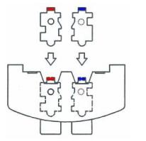
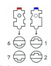
6. Replace the cover plate and secure with four (4) Red Screws, using a #2 screwdriver.
4. While holding the 'C' BUTTON, remove/add CODE (Red) and NONCODE (Blue) tumblers to create your desired code. Ex: 3 Red = 3-Digit Code / 6 Red = 6-Digit Code
5. After changing your code, release the 'C' BUTTON to secure the
7. TEST CODE before installing/re-installing lock.
WARNING:
Do NOT force tumblers into position!
For more helpful tips and installation instructions, visit www.LOCKEYUSA.com
Lockey® 2900 Series 2930 | 2945 | 2985 Installation Instructions & Template