LockeyUSA 2830 2835 Mechanical Keyless Lock Installation Instructions Updated 1.8.2020
Open the original PDF document
View PDF

2830 Knob/2835 Lever Mechanical Keyless Lock Installation Instructions
Fig. 4
Continued on Reverse Side
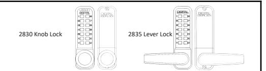
IMPORTANT INFORMATION ABOUT YOUR LOCK
- 1. When the door is closed, the system locks automatically.
- 2. From the inside, unlock using the knob/lever handle.
- From the outside, unlock by pressing 'C' (CLEAR), followed by your User Code.
- Your lock is equipped with a PASSAGE FUNCTION, allowing you to leave the door unlocked.
**USING THE PASSAGE FUNCTION WILL COMPROMISE THE SECURITY OF THIS LOCK**
-To enable the passage function:
Press 'C' (CLEAR), then 'Y' (PASSAGE), then enter User Code.
-To disable the passage function:
Press 'Y' (PASSAGE), followed by 'C' (CLEAR).
-To disable the passage function PERMANENTLY:
Remove the 'Y' (PASSAGE) tumbler, leaving that slot empty.
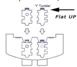
IMPORTANT: Always press and hold the 'C' Button when removing and inserting Tumblers. Refer to 'How to Change Code' instructions on reverse side.
| No. | Part Name | Included |
|---|---|---|
| 1 | Outside Body | 1 |
| 2 | Inside Body | 1 |
| 3 | Handle (2835 Lever/2830 Knob) | 2 |
| 4 | Rubber Trim Plate | 2 |
| 5 | Strike Plate | 1 |
| 6 | Mortised Striker | 1 |
| 7 | Spindle | 1 |
| 8 | Allen Wrench | 1 |
| 9 | Machine Screw M4 x 40mm | 2 |
| 10 | Machine Screw M4 x 30mm | 50mm | 1 | 1 |
| 11 | Wood Screw M4 x 16mm | 4 |
| 12 | Extra Code Tumblers (Red) | 1 |
| 13 | Extra Non-Code Tumblers (Blue) | 2 |
| 14 | Adjustable Latch 2 3/8" - 2 3/4" | 1 |
| 15 | Support Pin | 1 |
| 16 | Tweezers | 1 |
| 17 | Hex Bolts | 2 |
Step 1: Change User Code/Combination (OPTIONAL)
To change user code/combination, see instructions on reverse side.
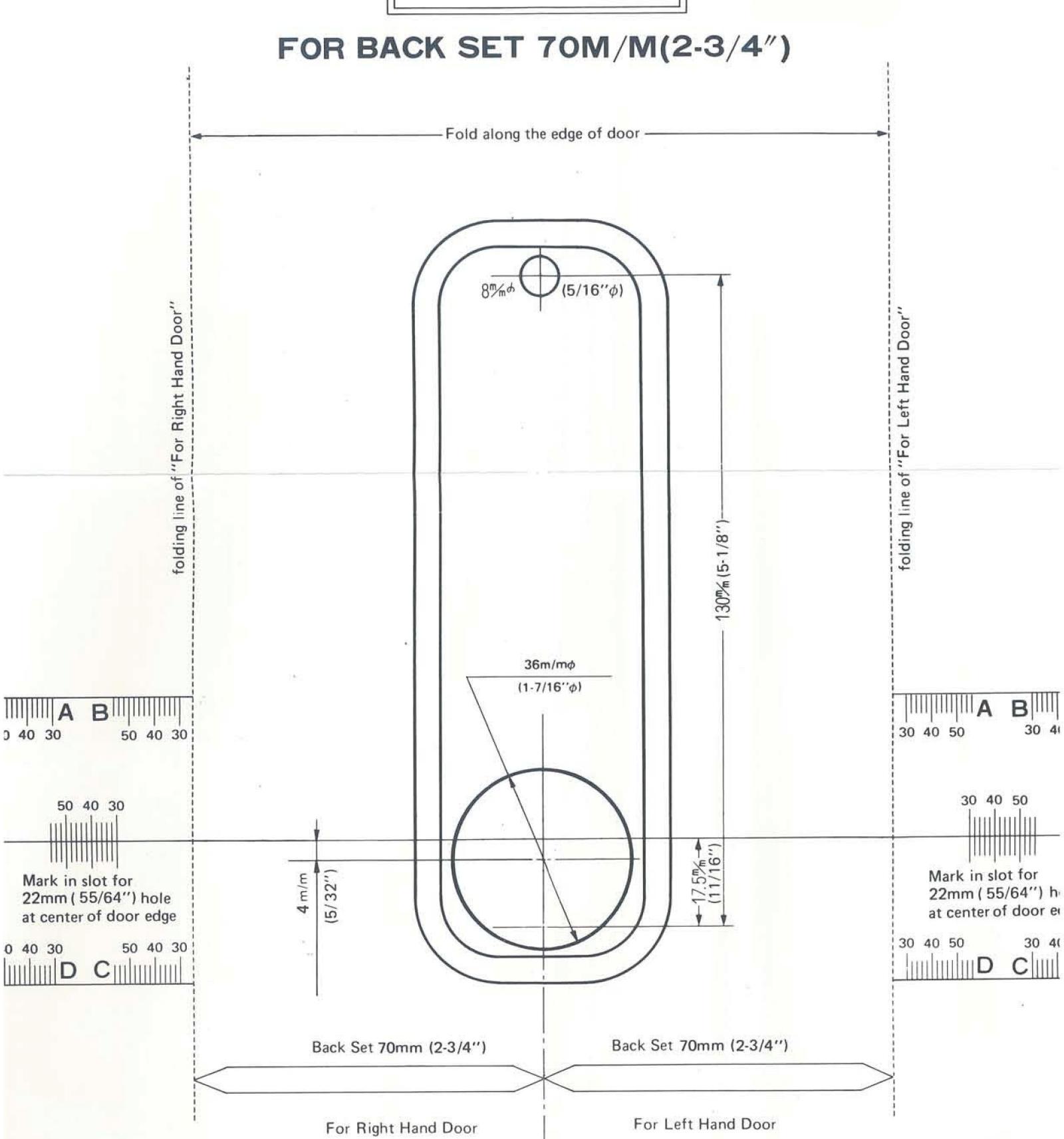
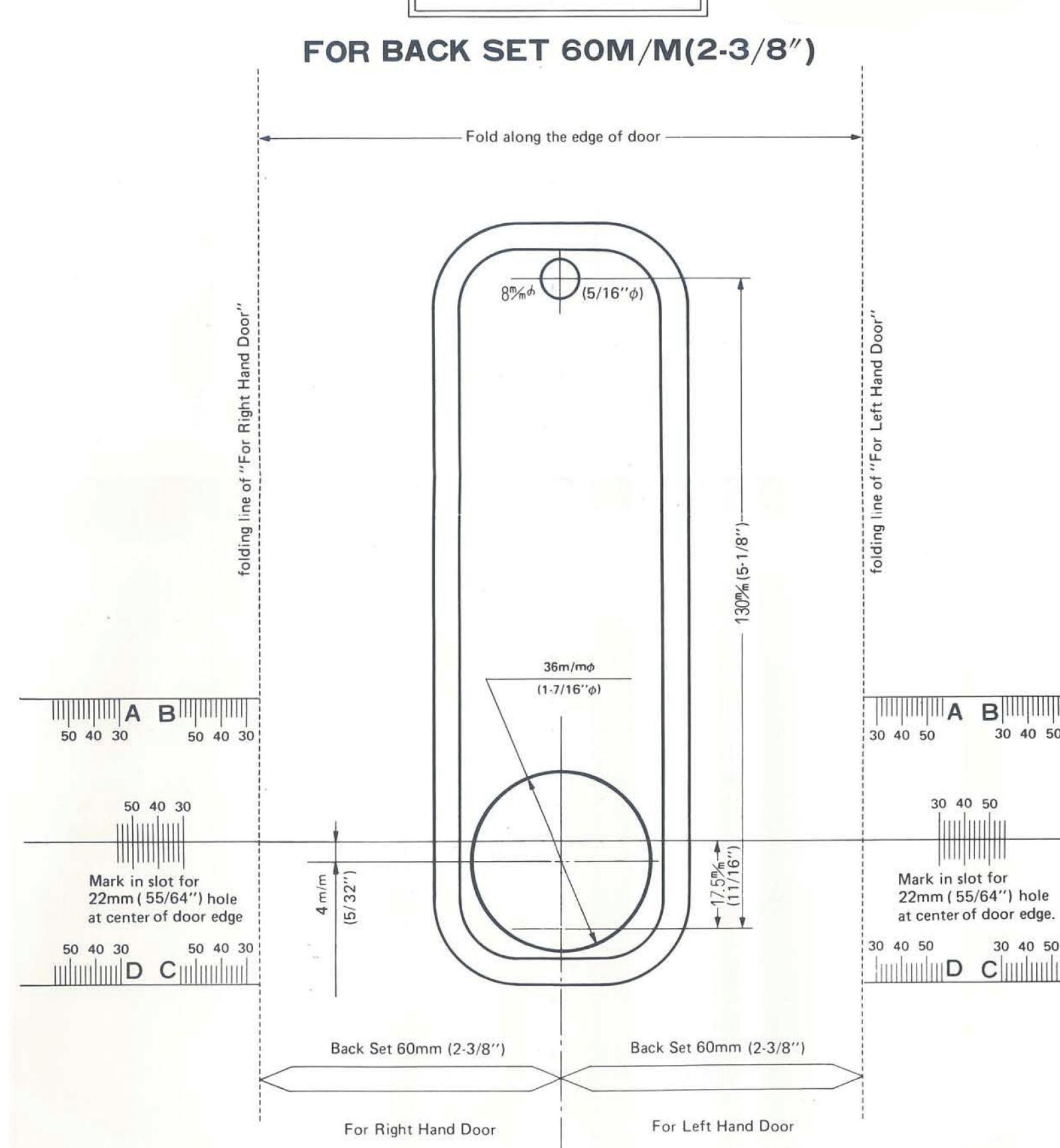
Step 2: Prep Door for Installation with Template
Place template (supplied) on door and fold along door's edge.
Mark holes for 2 3/8" or 2 3/4" backset. Drill holes as instructed.
Note: For pre-prepped 2 1/8" doors, you only need to drill top hole.
Step 3: Identify Door Handing
Right-Hand Doors – From exterior of door, hinges are on right-side (Fig. 1). Left-Hand Doors – From exterior of door, hinges are on left-side (Fig. 2).
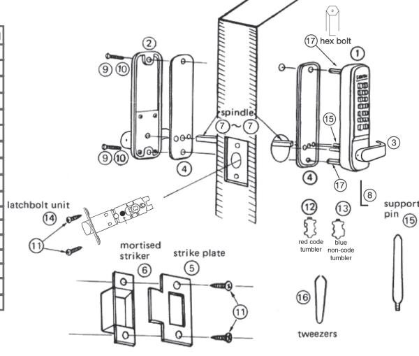
For Right-Hand Doors: Install Support Pin (#15) in position 'A'. For Left-Hand Doors: Install the Support Pin (#15) in position 'B'.
Now, install/screw Hex Bolts (#17) into the top and bottom as shown.
Fig. 3 Fig. 1 Fig. 2 RIGHT HAND LEFT HAND RIGHT HAND LEFT HAND 9O HINGE 04 90 04 0 (15) Support Pin "Support Pin" to (B) "Support Pin" to (A)
Step 4: Install Handles (2835 Levers or 2830 Knobs)
Using Allen Wrench (#8), install handles to the inside and outside bodies. Secure with set screws.
Note: For 2835, levers should point towards the door hinges.
Note: The 2835 is equipped with a built-in slip clutch lever handle to prevent damage in the event of an attempted forced entry.
If lever handle is in position shown (far right), pull lever back to desired position.
Slip Clutch Slip Clutch Slip Clutch Slip Clutch Slip Clutch Slip Clutch Slip Clutch Slip Clutch Slip Clutch Slip Clutch Slip Clutch Slip Clutch Slip Clutch Slip Clutch Slip Clutch Slip Clutch Slip Clutch Slip Clutch Slip Clutch Slip Clutch Slip Clutch Slip Clutch Slip Clutch Slip Clutch Slip Clutch Slip Clutch Slip Clutch Slip Clutch Slip Clutch Slip Clutch Slip Clutch Slip Clutch Slip Clutch Slip Clutch Slip Clutch Slip Clutch Slip Clutch Slip Clutch Slip Clutch Slip Clutch Slip Clutch Slip Clutch Slip Clutch Slip Clutch Slip Clutch Slip Clutch Slip Clutch Slip Clutch Slip Clutch Slip Clutch Slip Clutch Slip Clutch Slip Clutch Slip Clutch Slip Clutch Slip Clutch Slip Clutch Slip Clutch Slip Clutch Slip Clutch Slip Clutch Slip Clutch Slip Clutch Slip Clutch Slip Clutch Slip Clutch Slip Clutch Slip Clutch Slip Clutch Slip Clutch Slip Clutch Slip Clutch Slip Clutch Slip Clutch Slip Clutch Slip Clutch Slip Clutch Slip Clutch Slip Clutch Slip Clutch Slip Clutch Slip Clutch Slip Clutch Slip Clutch Slip Clutch Slip Clutch Slip Clutch Slip Clutch Slip Clutch Slip Clutch Slip Clutch Slip Clutch Slip Clutch Slip Clutch Slip Clutch Slip Clutch Slip Clutch Slip Clutch Slip Clutch Slip Clutch Slip Clutch Slip Clutch Slip Clutch Slip Clutch Slip Clutch Slip Clutch Slip Clutch Slip Clutch Slip Clutch Slip Clutch Slip Clutch Slip Clutch Slip Clutch Slip Clutch Slip Clutch Slip Clutch Slip Clutch Slip Clutch Slip Clutch Slip Clutch Slip Clutch Slip Clutch Slip Clutch Slip Clutch Slip Clutch Slip Clutch Slip Clutch Slip Clutch Slip Clutch Slip Clutch Slip Clutch Slip Clutch Slip Clutch Slip Clutch Slip Clutch Slip Clutch Slip Clutch Slip Clutch Slip Clutch Slip Clutch Slip Clutch Slip Clutch Slip Clutch Slip Clutch Slip Clutch Slip Clutch Slip Clutch Slip Clutch Slip Clutch Slip Clutch Slip Clutch Slip Clutch Slip Clutch Slip Clutch Slip Clutch Slip Clutch Slip Clutch Slip
Step 5: Adjust Latch (if necessary) and Install
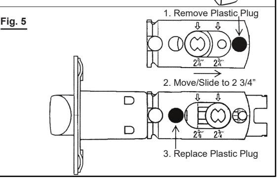
Adjustable Latch (#14) is preset to 2 3/8" backset.
To adjust: Remove plastic plug, slide to 2 3/4", and replace plastic plug as shown (Fig. 5). Insert Adjustable Latch (#14) into the door.
Secure with two (2) Wood Screws (#11).
INSTALLATION INSTRUCTIONS CONTINUED:
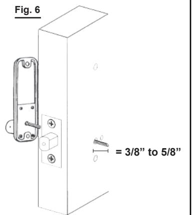
Step 6: Verify Correct Spindle Length (Fig. 6)
With Adjustable Latch (#14) installed, hold the Inside Body (#2) and Rubber Trim Plate (#3) to the door. Place Spindle (#7) through Latch, into the Inside Body, as far as possible.
Spindle should extend from exterior of door 3/8" min. to 5/8" max.
If Spindle (#7) is too long, cut it to the correct length using Pliers.
*IMPORTANT:
If spindle extends less than 3/8" it may not engage the lock.
If spindle extends more than 5/8", it will cause the lock to bind.
Step 7: Install the lock
Place the Rubber Trim Plate (#4) on the backside of the Outside Body (#1).
Place the Outside Body on the door. The hex bolts (#17) should extend into the top and bottom holes.
The Support Pin (#15) should extend through the hole in the Latch (#14).
Insert the Spindle (#7) into the Outside Body (#1) ensuring it's in the proper angled position.
*IMPORTANT: SPINDLE POSITION/ANGLE
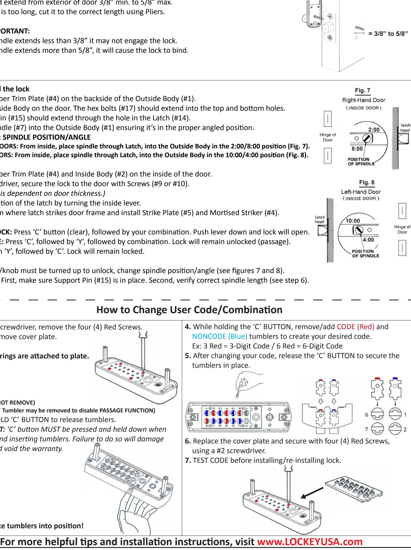
RIGHT-HAND DOORS: From inside, place spindle through Latch, into the Outside Body in the 2:00/8:00 position (Fig. 7). LEFT-HAND DOORS: From inside, place spindle through Latch, into the Outside Body in the 10:00/4:00 position (Fig. 8).
Place the Rubber Trim Plate (#4) and Inside Body (#2) on the inside of the door.
Using a screwdriver, secure the lock to the door with Screws (#9 or #10).
( Screw length is dependent on door thickness.)
Test the operation of the latch by turning the inside lever.
Locate position where latch strikes door frame and install Strike Plate (#5) and Mortised Striker (#4).
TEST YOUR LOCK: Press 'C' button (clear), followed by your combination. Push lever down and lock will open. TEST PASSAGE: Press 'C', followed by 'Y', followed by combination. Lock will remain unlocked (passage).
TO LOCK: Push 'Y', followed by 'C'. Lock will remain locked.
NOTE: If lever/knob must be turned up to unlock, change spindle position/angle (see figures 7 and 8).
If latch sticks: First, make sure Support Pin (#15) is in place. Second, verify correct spindle length (see step 6).
SAVE
How to Change User Code/Combination
tumblers in place.
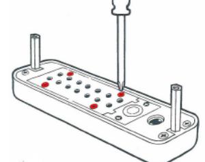
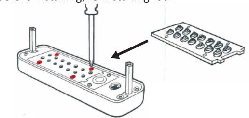
1. Using a #2 screwdriver, remove the four (4) Red Screws.
2. Carefully remove cover plate.
WARNING: Springs are attached to plate.
'C' = CLEAR (DO NOT REMOVE)
'Y' = PASSAGE ('Y' Tumbler may be removed to disable PASSAGE FUNCTION)
3. PRESS & HOLD 'C' BUTTON to release tumblers.
IMPORTANT: 'C' button MUST be pressed and held down when removing and inserting tumblers. Failure to do so will damage
the lock and void the warranty.
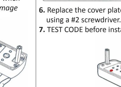
- 6. Replace the cover plate and secure with four (4) Red Screws,
- 7. TEST CODE before installing/re-installing lock.
WARNING:
Do NOT force tumblers into position!
DIGITAL DOOR LOOK
TEMPLATE
For Models: 2230, 2435, 2835
DIGITAL DOOR LOOK

For Models: 2230, 2435, 2835