LR6700 Template
Open the original PDF document
View PDF
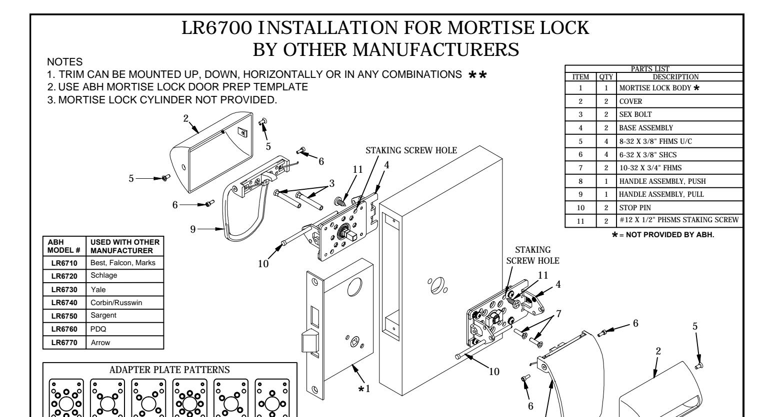

1. Install mortise lock body (item 1) per other manufacturer's instructions.
BEFORE MOUNTING BASE ASSEMBLIES, CAM MUST BE ROTATED AS PER DRAWING SHOWN IN DETAIL "A".
NOTE
- 2. Determine if pull trim is to be mounted vertical or horizontal. Place pull side assembly on pull side of door and rotate cam as per detail A, shown above. Insert (2) sex bolts (item 3) into base assembly (item 4) through the mortise lock body to match holes on door face and mount on pull side of door.
- 3. Determine if push trim is to be mounted vertical or horizontal. Place push base assembly (item 4) on push side of door and rotate cam as per detail A, shown above. On the push side base assembly, place the (2) 10-32 screws (item 7) to match the holes on the door face and fasten to the sex bolts (item 3) from the pull side base assembly. Test that the cams rotate freely on both sides of the door after tightening the screws.
- 4. Fasten (1) 6-32 SHCS (item 6) on one side of the pull handle assembly (item 9). Then insert the fastened socket cap screw and pull handle assembly into position into pull base assembly and fasten other socket cap screw to fully secure handle assembly. Insert (1) stop pin (item 10) through the base assembly on the opposite side of the direction the pull handle assembly is pointing. (See above diagram which illustrates proper location for stop pin given the pull handle mounting shown.) Test pull handle for proper operation to be sure stop pin was installed in appropriate base assembly hole. Note: If the base assembly is mounted horizontally, then the handle must be mounted pointing toward the hinge side.
- 5. Repeat above step #4 on the push side of the door for the push handle assembly (item 8). Insert (1) stop pin (item 10) through the push base assembly on the same side of the direction the push handle assembly is pointing. (see above diagram which illustrates proper location for stop pin given the push handle mounting shown.) Test push handle for proper operation to be sure stop pin was installed in appropriate base assembly hole. Note: if the base assembly is mounted horizontally, then the handle must be mounted pointing toward the hinge side.
- 7. To prevent the handle assemblies from possible twisting, which in turn can cause binding, determine which staking screw hole will be used for the push and the pull side handle assemblies (the staking screw installs on the staking screw hole location opposite the direction the handle is mounted). Install (1) #12 PHSMS staking screw (item 11) on each side.
- 8. Place covers (item 2) over handles and fasten each side with (2) flat head screws (item 5).
PATENT PENDING
HORIZONTAL
(MLIST POINT
HANDLES
LR6700-00.DWG

® www.abhmfg.com E-mail: abhinfo@abhmfg.com Architectural Builders Hardware Mfg., Inc. 1222 Ardmore Ave., Itasca, IL 60143 630.875.9900; FAX 800.9FAXABH (932.9224)
© 2016 ABH Mfg., Inc. printed in USA
LR6700 PAGE 1 OF 1 ISSUED 07-20-16