LCN_Senior_Swing_Series_2800_and_9500_Series_Installation_Instructions_107514
Open the original PDF document
View PDF

9500 Surface Applied Series
Senior Swing

Installation Instructions
740132 2800 Overhead Concealed Series
Caution
LCN Senior Swing
The Senior Swing Power Operator System is a low energy product and must conform to the latest version of ANSI/BHMAA156.19 (American National Standard for Power Assist and Low Energy Power Operated Doors).
Installation Instructions
All installation instructions are valuable references and should not be discarded. They should be given to the building owner or maintenance supervisor after installation is complete.
Caution
Improper installation or set up may result in personal injury or property damage. Follow all instructions carefully. For answers to questions, call:
Technical Support 1-877-671-7011
important
These instructions are presented in step-by-step sequence. It is very important that installation begins with "1. Pre-Installation Site and Product Check" (page 4) and continues as directed after each section.
warning
Always disconnect main power to the operator prior to replacing.
Table of Contents
| General 2 |
|---|
| 1 Pre-Installation Site and Product Check (Surface and Concealed) 3 |
| 2 Header Installation (Concealed) 4 |
| 3 Header Installation (Surface) 5 |
| 4 AC Power and Ground Wiring (Surface and Concealed) 7 |
| 5 Operator Installation (Surface and Concealed) 8 |
| 6 Pivot Block Installation (Concealed, Center Pivoted) 9 |
| 7 Breakaway or Fixed Stop Installation (Concealed, Center Pivoted) 10 |
| 8 Control Box Installation (Surface and Concealed)11 |
| 9 Control Box Wiring (Surface and Concealed) 12 |
| 10 Finger Guard Installation (Concealed, Center Pivoted) 13 |
| 11 Door and Arm Installation (Concealed, Center Pivoted) 14 |
| 12 Arm Installation (Surface and Concealed) 16 |
| 13 Glazing (Surface and Concealed) 16 |
| 14 Control Box Functions (Surface and Concealed) 16 |
| 15 Plate Installation (Surface and Concealed) 17 |
| 16 Release for Service (Surface and Concealed) 17 |
General
The Senior Swing is an automatic electromechanical swinging door operator for a single door, simultaneously operated, or independently operated pair of doors. The concealed application operates center pivoted, offset pivoted, or butt hung/hinged doors. The surface application operates balanced (push side only), center pivoted, offset pivoted, or butt hung/hinged doors in either push or pull mode.
When activated, the Senior Swing drives the door to the full open position, then electrical power is turned off and the door is closed by spring force. The activating circuit opens the door from any position in the closing swing. During a power failure, the Senior Swing acts as a manual door closer (size 3). Door opening and closing cycles, including opening speed, back check speed, hold open time delay, closing speed, and latch position, are adjustable.
A IMPORTANT A
Do not install the Senior Swing unless all of the following conditions are correct.
- 1a Check that the product model is correct for the required application.
- 1b Check that all parts listed on the bill of material are in the shipping container.
- 1c Check architectural and final approved shop drawings for position of frame and openings.
- 1d For concealed applications, check that the opening allows 1/4" at each side and at the top so that the frame and the header can be plumbed square and caulked.
- 1e For surface mount applications onto 2" frames, consult factory to determine if mounting plate is required.
- 1f Special tool may be required for installation of rivet nuts.
- 1g Check for sufficient header clearances:

- 1h For a ramped floor, check that the break in the grade occurs at the edge of the 2" threshold and slopes away from the entrance to allow proper door swing or panic breakaway.
-
1i Check that a 120 volt, single phase, 60 Hz, fused, 15 amp, 3-wire power supply is available at the side jamb with approximately 12" of wire available to connect to the operator. UL approved type flexible conduit is recommended for the 120 volt power line.
- The 120 volt power supply must be a dedicated circuit from the main circuit breaker panel and must not be connected into a building lighting system operating fluorescent lights.
- For concealed applications, continue with "2. Header Installation (Concealed)" on page 5.
- For surface applications, continue with "3. Header Installation (Surface)" on page 6.
2 Header Installation (Concealed)
- ① Note: Install concealed application headers so there is 1/8" between the bottom of the header and the top of the door.
- 2a Prepare existing jamb tubes using template 740069, then install four 1/4-20 rivet nuts inside each jamb tube.
- Align the header with the jamb tubes. For headers with a single operator, position the end of the header containing the operator brackets near the pivot side of the opening (Figure 2-1). Secure the header to the jamb tubes with four 1/4-20 hex head screws at each end (Figure 2-2).

- 2c Stand the header/jamb tube assembly in the opening.
- 2d Feed the 120 volt power conduit into the header (Figure 2-3). Leave 12" minimum of wire inside the header for final hookup.
- 2e Shim and square the side jamb tubes in position, then secure the jamb tubes in the opening.

• Continue with "4. AC Power and Ground Wiring (Surface and Concealed)" on page 8.
3 Header Installation (Surface)
- 3a For a header with two operators (for a simultaneously operated pair of doors), designate one end of the header as the companion operator end. (It does not matter which end.)
- 3b Refer to Figure 3-1 and step 3.3 and prepare wire access holes appropriate for the application in the header using template 740070. Be sure to position edge "A" of template 740070 as shown in Figure 3-1.

3c Install horizontal mounting brackets on the header per the instructions supplied with the brackets (Figure 3-2). Make sure the horizontal mounting brackets are oriented so the wire access holes in the header (see step 3.2) face up or face the door and, for single operator headers, the operator brackets inside the header are near the hinge side of the opening.

- L NOTE: Install surface applied headers with the following spacing between the bottom of the header and the top of the door: Pull arm application: 1-1/8" Push arm application: 1"
- 3d For aluminum storefront or aluminum tube frame, install the header with horizontal mounting brackets to the jams per the instructions supplied with the horizontal mounting brackets (Figure 3-3). shim

mounting
3e Hollow metal and wood frames require the use of a -18 mounting plate, sold separately (Figure 3-4).

3f Feed the 120 volt power conduit into the header (Figure 3-5). Leave 12" minimum of wire inside the header for final hookup.

• Continue with "4. AC Power and Ground Wiring (Surface and Concealed)" on page 8.
4a Connect the 120 volt power wires to the AC power cable (part number 761463) and header end plate as shown in Figure 4-1.

• Continue with "5. Operator Installation (Surface and Concealed)" on page 9.
5 Operator Installation (Surface and Concealed)
For double operator systems with differently handed operators, make sure that the correct operator is installed in each end of the header. The handing of the operator (R.H. or L.H.) is indicated on a label on the operator.


- 5b Connect the end of the green operator ground wire to the rear operator mounting bracket in the header (Figure 5-1) using the #10-32 hex head green ground screw supplied in the operator screw pack.
- 5c Make sure there is a rubber grommet inside each of the four operator mounting holes (Figure 5-2).
- Line up the four mounting holes on the operator with the four mounting studs on the operator brackets (Figure 5-3). Make sure that the operator cable (with 6-pin connector) is hanging down freely and push the operator up onto the mounting studs. Make sure cables are not pinched when operator is installed. (The mounting studs fit snugly into the grommets, and firm pressure may be required to get the operator into position.)
- 5e Secure the operator to the header using four 5/16-18 hex head screws and washers (Figure 5-3). Tighten the screws until they make contact with the mounting studs on the operator brackets.
- 5f Connect the other end of the green ground wire to the small hole in the bottom of the operator (Figure 5-3).
- 5g For a header with two operators, install the second operator in the same manner.
- For center pivoted doors, continue with "6. Pivot Block Installation (Concealed, Center Pivoted)" on page 10.
- For other doors, continue with "8. Control Box Installation (Surface and Concealed)" on page 12.
6 Pivot Block Installation (Concealed, Center Pivoted)
- NOTE: This section is applicable ONLY if using the factory supplied lower pivot block (with pivot post attached) on center pivoted doors. If not being used, continue with "7. Breakaway or Fixed Stop Installation (Concealed, Center Pivoted)" on page 11.
- 6a Position the lower pivot block (Figure 6-1) as shown in Figure 6-2 oriented so the pivot post is 2-3/4" or 3-3/4" (nominal) from the jamb, as necessary.
- 6b Use the pivot block as a guide and mark and prepare four mounting holes for appropriate fasteners for the mounting surface.
- 6c Secure the pivot block in place with appropriate fasteners (Figure 6-3).
- ① NOTE: Pivot block shown installed for a door with a 3-3/4" mounting point. For 2-3/4" mounting point, reverse pivot.


• Continue with "7. Breakaway or Fixed Stop Installation (Concealed, Center Pivoted)" on page 11.
7 Breakaway or Fixed Stop Installation (Concealed, Center Pivoted)
NOTE: This section is applicable ONLY to center pivoted doors using the factory supplied breakaway or fixed stop. If not being used, continue with "8. Control Box Installation (Surface and Concealed)" on page 12.
Breakaway and Fixed Stop Operation
The function of the breakaway or fixed stop is to act as a mechanical stop on an inswinging door so the door cannot normally be opened in the outswinging direction.
The breakaway stop differs from the fixed stop in that, in a panic or fire condition, when approximately 50 lbs. of force is applied on the door from the inswinging side, the door will open in the outswinging direction. When this occurs, a switch in the breakaway stop disables the automatic operation of the door. The door then remains inoperative and in the breakaway position until it is manually pushed back through the opening to the inswinging side. This action resets the breakaway stop and restores automatic operation.
7a Orient the breakaway stop according to the directions on the switch label (Figure 7-1). The "OPENING DIRECTION OF DOOR" arrow should point in the direction that the door opens during normal operation.

7b Install the breakaway or fixed stop inside the header approximately 2-1/4" from the latch end using the four #8-32 x 3/4" screws supplied with the stop (Figure 7-2). Mounting holes for the stop have been prepared in the header at the factory.

• Continue with "8. Control Box Installation (Surface and Concealed)" on page 12.
8 Control Box Installation (Surface and Concealed)
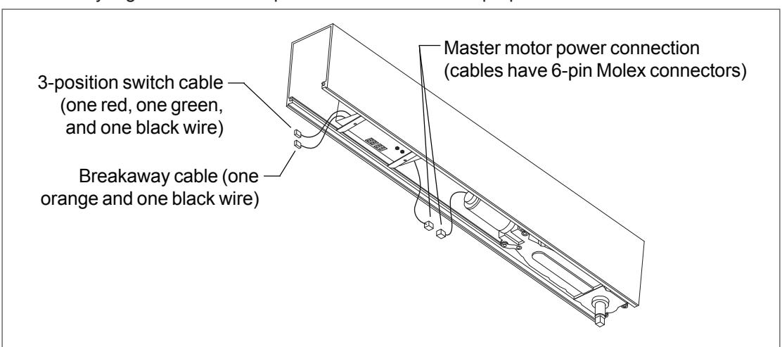
- 8a Orient the control box so the keypad faces down and the 6-pin Molex connector faces the operator for a single system or the master operator for a double system (Figure 8-1).
- 8b Raise the control box into the header and rotate the two mounting bars so they engage the slots that run the length of the header (Figure 8-2).
- 8c See Figure 8-3 for final positions of operator(s) and control box inside the header.



• Continue with "9. Control Box Wiring (Surface and Concealed)" on page 13.
A CAUTION A
High voltage wiring must be separated from low voltage wiring by UL listed wiring for the control box, operators, and low voltage accessories.
A CAUTION A
When joining or separating a Molex plug and receptacle, do not push or pull on any of the wires. This may cause a wire to be pulled loose from a terminal, which may result in a malfunction.
- 9a Single operator system minimum wiring requirements:
- AC power
- · Master motor power
- · Breakaway switch or jumper
Double operator system minimum wiring requirements:
- AC power
- · Master motor power
- Companion motor power
- · Breakaway switches or jumpers; if two Breakaway switches are used, wire switches in series
- 9b For wiring of companion operator and additional accessories, see the Senior Swing Control Box installation instructions.
- 9c Dress all wires neatly together and use clips to retain wires in their proper locations.
- For center pivoted doors, continue with "10. Finger Guard Installation (Concealed, Center Pivoted)" on page 14.
- For other doors, continue with "12. Arm Installation (Surface and Concealed)" on page 17.
10 Finger Guard Installation (Concealed, Center Pivoted)
- (i) NOTE: This section is applicable ONLY to center pivoted doors using the factory supplied finger guard. If not being used, continue with "11. Door and Arm Installation (Concealed, Center Pivoted)" on page 15.
- 10a Scribe a line down the center of the pivot side door jamb (Figure 10-1).
- 10b If necessary, cut down the finger guard to fit the installation.
- 10c Align the center of the finger guard over the scribed line. Use the screw holes in the finger guard as guides to locate the mounting holes, and drill #21 (0.159" dia.) mounting holes in the door jamb.
- 10d Secure the finger guard to the door jamb with #10 self-threading screws.
- 10e Make sure there is one mounting screw approximately 1" from each end of the finger guard. If necessary, drill additional mounting holes in the finger guard and door jamb in these locations and install #10 self-threading screws.

• Continue with "11. Door and Arm Installation (Concealed, Center Pivoted)" on page 15.
11 Door and Arm Installation (Concealed, Center Pivoted)
11a Prepare door for arm (Figure 11-1).

11b Install top arm and bottom pivot using screws supplied with those components (Figure 11-2). Use machine screws for metal door; use wood screws for wood door.

11c Orient the arm in the breakout position (Figure 11-3). Install the arm in the breakout position by pressing the arm onto the spindle until the end of the spindle is flush with the bottom surface of the arm (Figure 11-4). Tighten the Allen head cap screw on the arm (Figure 11-4).

11d Position the door so the arm is in the top channel of the door and gently slide the door up against the lower pivot (Figure 11-5).
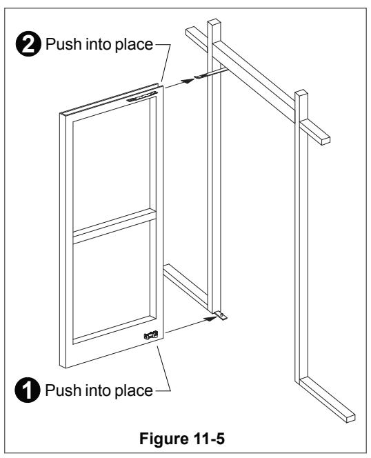
- 11e Lift the door slightly and push back until the bottom pivot locks into place.
- 11f Raise the nose of the door and push back until the top arm snaps into place.
- 11g Align the door in the open position (perpendicular to the opening).
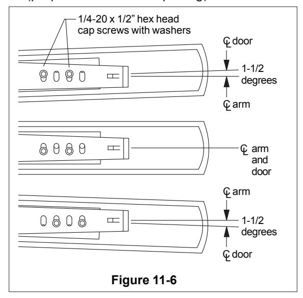
- 11h Install two 1/4-20 x 1/2" hex head cap screws and washers through two of the oval holes in the arm and into the top attachment arm (Figure 11-6).
- 11i Install screws in whichever of the positions shown align with the door in the open position (perpendicular to the opening).
- 11j Check door operation by pushing door to normal closed position, continue pushing through breakaway stop to 90 degree open position, and then release door. Door should close.
A CAUTION A
If the operator is not connected to the control box, the door will slam closed when released.
Continue with "13. Glazing (Surface and Concealed)" on page 17.
Surface
Push Arm: For surface header applications. To install, see separate instructions for Push Arm & Link Assembly.

Pull Arm: For surface header applications, see separate instructions for Pull Arm Assembly.

Offset Arm: For concealed header applications with butt hung and offset pivoted doors. To install:
Concealed
- 1. Prepare door and install slide channel (see separate Installation Instructions for Offset Arm).
- Note position of operator spindle. Turn on operator power. Momentarily short activation wires so spindle slowly rotates toward full open position and stops. Continue doing this until spindle reaches full open position (refer to Figure 11-3), then join activation wires together with a wire nut.
- 3. Insert arm slide into slide channel, slide arm onto spindle, and tighten arm Allen head cap screw.
- 4. Remove wire nut from activation wires; turn off power.

Continue with "13. Glazing (Surface and Concealed)"
13 Glazing (Surface and Concealed)
A CAUTION A
Glazing material must comply with the ANSI standard specification.
A CAUTION A
Operator speed adjustments cannot be set properly until after the door is glazed.
Continue with "14. Control Box Functions (Surface and Concealed)"
14 Control Box Functions (Surface and Concealed)
To set control box functions, see the Senior Swing Control Box installation instructions.
• Continue with "15. Plate Installation (Surface and Concealed)" on page 18.
15 Plate Installation (Surface and Concealed)
1. Install spindle plate and filler plate (Figure 15-1). Spindle platecutout fits over operator spindle.

Surface Concealed
For concealed header applications using offset arm with butt hung and offset pivoted doors only:
- 1. Prepare header dress plates for concealing channel (Figure 15-2; see separate Installation Instructions for Offset Arm).
- 2. Install concealing channel (Figure 15-2).

• Continue with "16. Release for Service (Surface and Concealed)"
16 Release for Service (Surface and Concealed)
- 16a Remove all tools, installation equipment, and debris from the vicinity of the door.
- 16b Install all safety, traffic control, and instruction decals on the door as required by the latest revision of ANSI/ BHMAA156.19 for the Senior Swing. This is very important! Failure to do this leaves the installer LIABLE for any accident that might occur. This must be done!
- 16c Verbally instruct the owner or person in charge of the proper operation of the door.
- 16d Instruct the owner or person in charge to routinely inspect the door for occasional damage, developing problems, minor preventive maintenance.
- 16e Instruct the owner or person in charge who and where to call for service when required.
important
Make sure to install all safety, traffic control, and instruction decals on the door as required.
Customer Service
1-877-671-7011 www.allegion.com/us
