LCN General Information Catalog Section 109514
Open the original PDF document
View PDF

Trinity Church…
In 1876, Mr. L. C. Norton was sent to Boston, Massachusetts to help build the Boston Trinity Church. The church took over four years to complete. The church was located on the Back Bay facing south and west thus at times, encountering some very severe wind conditions. The church began operation in 1880, the pastor, Rev. Brooks and his congregation quickly found out that the strong winds would make the doors close with a thunderous bang. Needless to say, the pastor was not going to stand for all the noise; those doors needed to be controlled! This prompted Mr. Norton to action.
Mr. Norton's first attempt to remedy the situation was to hang the doors on double-spring hinges. Mr. Norton had now uncovered a second problem. The slamming stopped but now the strong winds made the doors stand open. The cold, drafting air raised protest amongst the people in the church. He tried rubber stops, special door linings, and some other ideas. Nothing worked. One day, continuing to ponder the problem with the doors at the Trinity Church, he put some things away in a closet and being in a hurry, he threw the door shut. To his amazement, the door did not slam. Instead, the door bounced back. He tried this over and over with the same result. An idea came to him; he rushed to town and purchased a beer pump. With the beer pump, a makeshift arm, and some special brackets he had designed, Mr. Norton installed his invention on one of the exterior church doors. He opened the door and let it go…CRASH! The door slammed so hard it broke the pump into many pieces.
Mr. Norton spent many months trying to solve the problem; finally, he used the principles of the lever, improved the main components, and decided to reposition the device on the door. He took his updated version and again installed it on one of the troublesome church doors. Rev. Brooks saw Mr. Norton's new design and to his delight, the closer worked perfectly. Mr. Norton had used air pressure to make the doors close quietly. The problems with the doors at the Boston Trinity Church were now solved.
Growing Pains…
Soon after the doors at the Trinity Church were under control, Mr. Norton formed a company to manufacture his new found invention. The factory was located in Boston, Massachusetts and business started out strong. In fact, at times, there were more orders than production could match.
Time flew by. Mr. Norton's company began to experience difficulty. Competition was fierce. Some competitors began to infringe on patents, which drained Mr. Norton of both cash flow and other resources. Mr. Norton also made a few business decisions that would hamper company growth. The early years presented other challenges too. New closer designs were being introduced at an increasingly fast pace. This quick growth brought about some challenging quality issues. Business associates both good and bad, came and went. The factory moved to Brooklyn, New York and then back to Boston, Massachusetts. In these years, the door closer business was a volatile one. Most good companies were forced into change whether they liked it or not. The door closer industry was no exception.
New Beginnings…
Competition drove Mr. Norton in a new direction. His air check had worked well but was slowly giving way to new technology. In 1900, Mr. Norton developed a liquid door check. This new liquid door check controlled the door through the
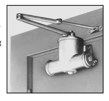
entire door swing by incorporating three independent hydraulic regulations. Back-check, general speed, and latch speed were necessary for total door control. In 1908, the company was moved to Chicago, Illinois. By the early 1920's, the door closer business was doing well but Mr. Norton was wearing down, he needed help.

In 1925, Mr. L. C. Norton teamed with Mr. D. R. Lasier and formed the Norton-Lasier Company. The business was located at 466 West Superior Street in Chicago, Illinois. Norton & Lasier knew that if their company was to survive, they must build a far superior product at a very fair price. They called their improved door closer an LCN. After a few years,

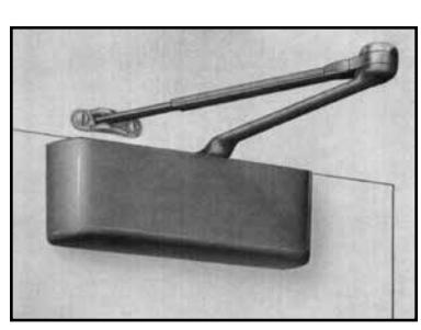
high-quality traditional style closers all over the world. Many of these closers are still in use today. In 1949, the factory moved to Princeton, Illinois. In 1958, LCN introduced the heavy-duty 4010/4110
series closer. Schlage Lock Company purchased LCN in 1959. In 1974, Ingersoll-Rand purchased Schlage Lock Company (and LCN). Today, LCN offers a complete line of door control products including heavy-duty hydraulic closers, power operators, fire/life safety closer/holders, high security closers & more.
The model numbers may have changed but the passion, quality, and excitement will always remain. LCN closers are made with premier materials and our products are
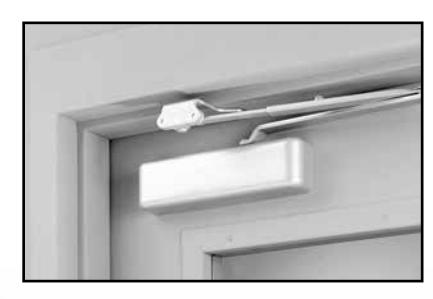
tested far beyond the industry requirements.
1851 – Lewis C. Norton born May 5th in New Hampshire.
1880 – First door closer installed at Boston Trinity Church.
1881 – Manufacturing begins at Boston plant.
1900 – Mr. Norton introduces a liquid door check.
1908 – Company moves to Chicago.
1917 – David R. Lasier joins company as timekeeper.
1925 – Norton-Lasier Company begins operation.
1929 – L. C. Norton moves to California. D. R. Lasier heads up company.
1930 – Norton-Lasier Company produces wooden riding toys to cope with the Great Depression.
1937 – L. C. Norton passes away on November 4th.
1942 – Norton-Lasier Company produces hydraulic aircraft fittings for the war effort.
1948 – Norton-Lasier Company officially changes name to LCN .
1958 – LCN introduces the 4010/4110 series door closer.
1959 – LCN sold to Schlage Lock Company.
1972 – LCN introduces Sentronic line of fire/life safety holder/closers.
1973 – LCN introduces the 4040 series door closer.
1974 – Schlage Lock (and LCN) sold to Ingersoll-Rand.
1978 – LCN introduces Equalizer units.
1980 – Production on traditional series ends.
1981 – LCN introduces the 1460 series door closer.
1981 – LCN introduces AutoEqualizer™ units.
1985 – LCN introduces the 1070 series door closer.
1993 – LCN introduces the powder coat finish.
1995 – LCN introduces Electric Operator units.
1996 – LCN introduces the 1520 series door closer.
1998 – LCN introduces the 1370 series door closer.
2006 – LCN introduces the new 4030 series door closer to replace the 1520 closer series.
2006 – LCN introduces the new Senior, Astro and
Middle Swing Digital Control Box. 2007 – LCN introduces the new Tri-Volt Magnets.
2007 – LCN introduces the new 4040XP.
2007 – LCN introduces the new 1260 Series.
2013 – In December of 2013, the Security Technologies division of Ingersoll Rand became its own publicly traded company called Allegion.
2015 – LCN introduces the 1250, 1450 and 4050 series cast aluminum door closers.
General information
Table of contents
| GENERAL INFORMATION | |
|---|---|
| History of Door Closers & LCN | A2-3 |
| Table of Contents | A4 |
| Finishes | |
| Warranty | |
| Door Closer Specialists | Δ7 |
| Specifications | |
| ANSI Cross Reference | Δ11-13 |
| Materials | ۱۱۸۸۱۸ |
| Proper Door Control | |
| Mechanical Considerations | |
| Glossary of Abbreviations | |
| Glossary of Terms | |
| Olossary or Terris | AZJ-JI |
| 4000 SERIES SURFACE MOUNTED CLOSERS | |
| Product Selection Guide | R1-2 |
| 4010 Series | R3-6 |
| 4010T Series | |
| 4020 Series | |
| 4020T Series | |
| 4030 Series | |
| 4030T Series | |
| 4040XP Series | |
| 4040XPT Series4050 Series | |
| 4050T Series4110 Series | |
| 4110 Series |
//-כ/ם
כס חדם |
| 4000T Series | |
| 40001 Series | 000-000 |
| 1000 SERIES SURFACE MOUNTED CLOSERS | |
| Product Selection Guide | C1-2 |
| 1250 Series | |
| 1260 Series | |
| 1450 Series | |
| 1460 Series | C27-34 |
|
1460 Series
1460T Series |
C27-34 |
| 1460 Series |
C27-34
C35-41 |
| 1460 Series |
C27-34
C35-41 |
| 1460 Series | |
| 1460 Series | |
| 1460 Series |
C27-34
C35-41 D1-2 D3-6 |
| 1460 Series | C27-34D1-2D3-6D7-11 |
| 1460 Series | |
| 1460 Series | |
| 1460 Series | |
| 1460 Series | |
| 1460 Series | |
| 1460 Series | |
| 1460 Series | |
| 1460 Series | |
| 1460 Series | |
| 1460 Series | |
| 1460 Series | |
| 1460 Series | |
| 1460 Series | |
| 1460 Series | |
| 1460 Series |
| HIGH SECURITY CLOSERS SERIES | |
|---|---|
| Product Selection Guide | F1-2 |
| 2210 Series | |
| 4210 Series | |
| 4210T Series | |
| 4510 Series | |
| 4510T Series | |
| 15101 Sellesimminimminimminimminimminimminimminimm | |
| AUTOMATIC OPERATORS | |
| Product Selection Guide | G1-5 |
| Pneumatic Powered Systems | |
| 2610 Series | G11-14 |
| 4810 Series | G15-18 |
| 4820 Series | G19-22 |
| 4840 Series | |
| 7900 Series Control Boxes | G28-31 |
| Electrohydraulic Powered Systems | G32-34 |
| 4630/4640 Electrohydraulic Series | G35-36 |
| 4630 Series | G37-41 |
| 4640 Series | G43-47 |
| Electromechanical Powered Systems | G49-53 |
| Benchmark Unique Features | G54 |
| 9130 Series | G55-59 |
| 9140 Series | |
| 9150 Series | |
| Senior Swing Unique Features | G71 |
| 2810 Series | G73-78 |
| 2850 Series | G79-84 |
| 2860 Series | G85-90 |
| 9530 Series | |
| 9540 Series | G97-101 |
| 9550 Series | G103-108 |
| 9560 Series | |
| Actuators, Sensors & Accessories | G115-131 |
| DOOR HARDWARE |
ICN
121 West Railroad Avenue P.O. Box 100 Princeton, IL 61356-0100
For SSC Representative contact information, please visit www.allegion.com/us and click "Contact Us"
PAH60......H1
To view or download an electronic copy, visit www.allegion.com/us. LCN reserves the right to change the information contained in this catalog without notice.

LCN powder coating provides superior protection against the effects of weather conditions and is an environmentally friendly process. The high quality, chip resistant finish is far superior to any previously offered. Corrosion resistance surpasses 100 hours salt spray testing (four times the industry standard). Non-metallic components also provide the same high resistance to the effects of the elements. All LCN products must be shipped with a finish.
ALUM ALUMINUM (BHMA 689)
DKBRZ DARK BRONZE (BHMA 695)
STAT STATUARY BRONZE (BHMA 690)
LTBRZ LIGHT BRONZE (BHMA 691)

BLK BLACK (BHMA 693)

BRASS BRASS (BHMA 696)
LCN offers custom powder coating to provide a custom appearance and all the corrosion resistance of standard powder coat finishes at a nominal additional cost. LCN uses the RAL numbering system for the 150+ custom colors available. Contact your local SSC representative for a brochure showing the available custom colors. Note: Custom powder coat finishes require a metal cover.
Visible components such as metal covers, arms, fasteners, and finish plates are plated to match the selected finish. Surface mounted tracks are powder coated to compliment the plated finish. Hidden assemblies such as cylinders, tracks, and mounting plates are supplied with a powder coated finish. Plated finishes require handing of closers.
| US 3 | Bright Brass (BHMA 632) |
| US 4 | Satin Brass (BHMA 633) |
| US 10 | Satin Bronze (BHMA 639) |
| US 11 | Satin Bronze (BHMA 643) |
| US 15 | Satin Nickel (BHMA 646) |
| US 26 | Bright Chrome (BHMA 651) |
| US 26D | Satin Chrome (BHMA 652) |
Aluminum ALUM (BHMA 689) Dark Bronze DKBRZ (BHMA 695)
For installations where a higher level of protection against weather conditions, or the effects of a potentially corrosive atmosphere is required, LCN offers a special rust inhibiting (SRI) process. Ferrous metal components receive an SRI pretreatment and a standard powder coat finish of your choice, or a custom powder coat finish for a nominal additional cost. Closers treated with the SRI process exceed the 100 hour protection level available with standard LCN powder coated finishes. For details, contact your local SSC representative or the LCN factory.
LCN Senior Swing & Benchmark electromechanical power operators are offered with an anodized finish. Anodizing is an electrochemical process that thickens and toughens the protective oxide on aluminum metal.
Aluminum ANCLR (BHMA 628) Dark Bronze ANDKBRZ (BHMA 710)

Subject to the terms and conditions of this limited warranty, Schlage Lock Company, LLC (the "Company') extends a limited warranty against defects in material and workmanship for its LCN branded product(s) identified in the Product Table below ("Products") as installed in the original location.
This limited warranty applies to Products purchased on or after March 3, 2014.
Product Table - Cast Iron
| 4000 Series | 30 Years |
| 1460 Series | 30 Years |
| 1260 Series | 20 Years |
| Concealed, High Security (except 2210DPS) | 15Years |
|
Automatic Operators; SE, ME, HSA, SEH Series; SEM Magnets; 2210 DPS
(includes both electronic and mechanical components) |
2 Years |
Product Table - Cast Aluminum
| 1250 Series | 15 Years |
|---|---|
| 1450 Series | 25 Years |
| 4050 Series | 25 Years |
Term: The limited warranty period for Products is as stated in the Product Table above. The "Commencement Date" for a limited warranty period shall be the date of Company's delivery to the original purchaser of the Products. Proof of Product purchase may be required by Company to confirm the Commencement Date.
What Company will do: Company may require proof of Product purchase in order to provide coverage under this limited warranty. As Company's only responsibility and user's only remedy under this limited warranty, Company will furnish a replacement Product upon receipt and confirmation by Company, in its sole opinion, that the Product has, in fact, failed due to a manufacturing defect under normal use and maintenance. In the event a replacement Product cannot be provided, Company will either provide a suitable replacement Product or a refund in the amount of the original purchase price.
What is not covered: The following costs, expenses, and damages are not covered by the provisions of this limited warranty: (i) labor costs including, but not limited to, such costs as removal and installation of Product; (ii) shipping and freight expenses required to return Product to Company; (iii) failures, defects, or damage caused by any third party product or service; (iv) any other incidental, consequential, indirect, special and/or punitive damages, whether based on contract, warranty, tort (including, but not limited to, strict liability or negligence), patent infringement, or otherwise, even if advised of the possibility of such damages.
The provisions of this limited warranty do not apply to Product that is: (i) not the proper size for the application for which the Product is used; (ii) not installed in accordance with Company's published Product installation instructions; (iii) installed with improper parts and/or incorrect parts (NOTE: It is recommended that Product be installed with LCN fasteners provided with Product); (iv) improperly stored, maintained, or operated; (v) modified, repaired, or altered in Company's sole opinion, in any manner, without the express written consent of Company; (vi) used for purposes for which the Product is not designed or intended; (vii) subjected to misuse, abuse, negligence, or accident; or (vii) subjected to improper temperature, humidity, or other environmental conditions.
Note: 900/7900 Series compressors are not manufactured by Company and are excluded from coverage under this limited warranty. For more information, parts, or repairs concerning the compressors, contact the compressor manufacturer directly at (269) 926-6171.
Additional Terms: This limited warranty is in lieu of all other warranties, express or implied. Company does not authorize any person to create for it any obligation or liability in connection with Product. Company's maximum liability hereunder is limited to the original purchase price of the Product. No action arising out any claimed breach of this limited warranty by Company may be brought by the user more than one (1) year after the cause of action has arisen.
How local law applies: This limited warranty gives you specific legal rights, and you may also have other rights as permitted by law. Some local laws do not allow limitations on how long an implied warranty lasts or the exclusions or limitation of incidental or consequential damages so the limitations or exclusions provided herein may not apply to you.
Program and Warranty Claims: If product is to be claimed to be defective under this limited warranty, contact Customer Care at (877) 671-7011.
Note: Please contact LCN Customer Care prior to returning any product back to the factory. You will need prior authorization and an RMA for your return.

Since its founding in 1926, LCN has specialized in solving door control problems through the use information of high quality, innovative door control products. By adhering to high standards of performance, LCN has earned a leadership role within the industry and is committed to meeting door control challenges of the future. With representatives located throughout the world, LCN provides the products and services necessary to solve your door control problems.
The LCN formula for success
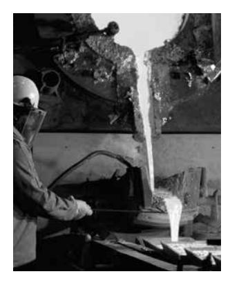
Materials
LCN is committed to providing the best door closers in the world. In addition to the mechanical advantages derived from proven designs, much of the durability of the closer and arm system is related to the materials used in their manufacturing.
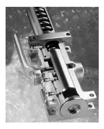
Extensive Abuse Test
Why do some hardware professionals claim that LCN stands for "Last Closer Needed?" LCN closers are put through grueling tests in which they exceed industry requirements.
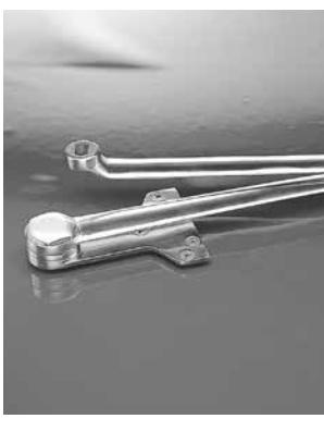
Forged Steel Arms
The closing power and control generated within LCN closers is transferred to the door through forged steel arms. Forged steel arms have greater strength, better appearance and less bulk.
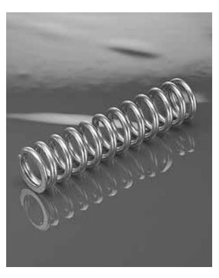
Chrome Silicon
Many closer manufacturers use less expensive oil-tempered springs, but LCN engineers know that such a spring loses up to 20% of its power after a few thousand cycles.
Heat-Treated
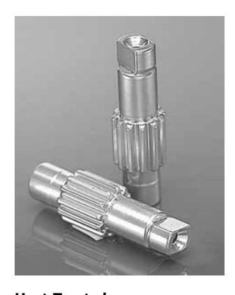
LCN steel pinions have larger, stronger teeth and are double heat-treated for the greatest possible strength on the shaft. Heat-treating makes the pinion harder, better able to resist wear after years of service and results in less stress on the cylinder.
Special Templates
When a standard door closer won't do the job, there is only one proven, reliable source for special solutions — LCN. With over 3,000 special templates on file, LCN can provide a door control solution for one-of-a-kind doors such as vault, balanced, over-sized and arch doors.
Hydraulic Fluid
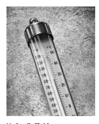
LCN uses a special formula hydraulic fluid with special lubrication properties to keep closer components working smoothly. This unique all-weather hydraulic fluid eliminates the need for seasonal adjustments.

Customer Service
At a time when machines are picking up more and more customer calls, real people are answering the phones at LCN. Every member of our customer service staff is trained and qualified to assist you with orders, closer selection and special applications.
A. Reference Standards
1. American National Standards Institute (ANSI/BHMA):
A117.1 Providing Accessibility and Usability for Physically Handicapped People A156.10 For Power Operated Pedestrian Doors
A156.4 Door Controls - Closers
A156.15 Life Safety Closer Holder Release Devices
A156.18 Materials and Finishes
A156.19 Power Assist and Low Energy Power
Operated Doors
2. Americans with Disabilities Act (ADA)
3. American Society for Testing and Material (ASTM): Specification B117-9 Method of Finish Corrosion Testing
4. Underwriters Laboratory (UL): 228 Door Closers-Holders UL10C Standard Positive Pressure Fire Test of Door Assemblies
UL10B Standard for Fire Test of Door Assemblies
5. National Fire Protection Association (NFPA) No. 80 Fire Doors and Windows No. 101 Life Safety Code
B. Source Quality Control
- 1. Obtain each kind of hardware (latch and lock sets, hinges, closers, etc.) from only one manufacturer, although several may be indicated as offering products complying with requirements.
- 2. All products shall meet grade 1 or the highest level of cycle test requirements of the applicable ANSI/BHMA standard.
C. Supplier Qualifications
- 1. Supplier must be a recognized builders hardware supplier who has been furnishing hardware in the projects vicinity for a period of not less than two years.
- 2. Supplier must be or employ an experienced hardware consultant who is available, at reasonable times during the course of the work, for consultation about the project's hardware requirements, to Owner, Architect, and Contractor.
D. Fire-rated Openings
- 1. Provide hardware for fire rated openings in compliance with NFPA Standard No. 80, NFPA Standard No. 101, and local building codes.
- 2. [Manual hold-open arm function not allowed.] Provide hardware which has been tested and listed by UL for types and sizes of doors required and complies with the requirements of door and frame labels.
PART 2 - PRODUCTS
A. General
1. Closers shall be installed to allow door swing as shown on plans. Doors swinging into exit corridors should provide for corridor clear width as required by codes.
A. General
All closers shall be as manufactured by LCN CLOSERS, Princeton, Illinois, USA, and shall have the following features:
- 1. [Applies to 4010, 4020, 4110, 4210, 4510, 5010 Series only.] All manual door closers shall be certified to exceed 15 million (15,000,000) full load operating cycles by a recognized independent testing laboratory.
- 2. All closers shall carry manufacturer's warranty, as stated on page 6.
- 3. All closers with electrical or pneumatic components shall carry a manufacturers two (2) year warranty. [Items 4 through 12 apply to closer cylinder, items 13 through 16 apply to closer arms.]
- 4. [Delete for 1250, 1450, and 4050] Fully hydraulic, rack and pinion action with high strength cast iron cylinders and one piece forged steel pistons.
- 5. Fluid of a type requiring no seasonal adjustments.
- 6. [Delete for 1460, 1260, 3030, 3130 4030 4040XP, 1250, 1450, and 4050 Series. 4040XP has a minimum 3/4" pinion shaft diameter.] Pinion shaft minimum diameter of 11/16".
- 7. Hydraulic regulation controlled by tamper-proof, non-critical screw valves, adjustable with a hex wrench.
- 8. Separate adjustments for backcheck, general speed, and latch speed.
- 9. [Applies to 1450, 1460, 4010, 4020, 4040XP, 4050, 4110, 4210, 4510, 5010 Series.] Where detailed on double lever arm closers, provide a delayed action feature to delay closing up to one minute from maximum opening to approximately 75º.
- 10. Backcheck shall be properly located for protection of the door, frame, and applied hardware.
- 11. [Applies to 2210, 4110, 4210, 4210T, 4510, and 4510T Series only.] Where detailed, provide advanced variable backcheck to start backcheck function at approximately 45º.
- 12. Include high efficiency, low friction full compliment pinion bearings.
- 13. [Delete for 1260, 1460, 6030 Series.] Forged steel main arms.
- 14. [Applies to 4110, 4210, 4510 Series and all EDA and CUSH arms.] Forged steel main and forearms.
- 15. [Applies to all single lever arm (track type) closers.] Where detailed, provide a quiet, low friction track and roller assembly and provisions for an optional bumper assembly to assist backcheck and/or hold-open clip.
- 16. [Applies to all double lever arm closers, except EDA or CUSH arms.] Reversible shoe to increase latching power of the closer.

B. Size of Closers
- 1. Sized in accordance with ANSI/BHMA Standard A156.4 as shown in the applicable TABLE OF SIZES listed in the current LCN General Catalog.
- 2. Closing power of non-sized cylinders shall be adjustable over a range of sizes ;[Applies to 1250, 1261, 1450, 1461, 1460T, 4011, 4021, 4040SE, 4040XP, 4040XPT, 4041DEL, 4050, 4111, 4211, 4511, 4631, 4642, 4811, 4822, 4841, 4031, 4031T Cylinders.]
C. Barrier Free Manual Closers
- 1. All closers for openings that must meet the minimum requirements of the ADA act, in lieu of ANSI/BHMA Standard A156.4, shall be sized in accordance with the applicable REDUCED OPENING FORCE table in the current LCN General Catalog.
- 2. All size 1 manual closers shall provide or be adjustable to provide less than 5 pounds opening force on a 36" door leaf and delay closing time in accordance with the ADA requirements.
D. Combination Door Closers and Holders
1. Provide closer/holders designed to hold the door in the open position under normal usage and to release and automatically close the door under fire conditions. Closer will include an integral electromagnetic holder mechanism designed for use with UL listed fire detectors, provided with normally closed switching contacts.
2. [Applies to all ME models.]
Where detailed, multi-point closer/holders shall incorporate a hold-open bypass feature from 0º up to either 80º or 140º.
3. [Applies to 4310 ME only.]
Where detailed, multi-point closer/holders shall provide a swing-free function with a no-drift feature.
E. High Security Closers
- 1. Provide closers designed to resist vandalism and tampering.
- 2. All exposed fasteners shall be TORX machine screws with a security pin.
- 3. All closer adjustments shall be shielded by the cover or finish plate, after installation.
- 4. Arm and, where furnished, high security roller assembly shall be designed to prevent disassembly.
- 5. [4210 and 4510 Series only.] All surface mounted high security closers shall include a cast iron cylinder certified by an independent testing laboratory to exceed fifteen million (15,000,000) operating cycles, heavy gauge metal covers with four mounting screws and double lever arms manufactured to prevent disassembly.
- 6. [4210T and 4510T Series only.] All surface mounted high security closers shall include a cast iron cylinder certified by an independent testing laboratory to exceed fifteen million (15,000,000) operating cycles, heavy gauge metal covers with four mounting screws, heavy duty arm with special security roller, and a heavy gauge high security track designed to eject foreign objects.
- 7. [2210 and 2210 DPS only.] All concealed high security closers shall include a cast iron cylinder certified by an independent testing laboratory to exceed fifteen million (15,000,000) operating cycles, 3/8" steel mounting plate, heavy duty arm with special security roller, and a heavy gauge high security track designed to eject foreign objects.
- 8. [2210 DPS only.] A built-in door position switch shall be optional with concealed closers.
F. Automatic Operators
- 1. Where low kinetic energy, as defined by ANSI/BHMA Standard 156.19, automatic operators are indicated for doors required to be accessible to the disabled. Provide pneumatic, electrohydraulic or electromechanical [2610, 2810, 2850, 2860, 4630, 4640, 4810, 4820, 4840, 9130, 9140, 9150, 9530, 9540, 9550, 9560 Series] operators complying with the ADA for opening force and time to close standards.
- 2. Full closing force shall be provided when the power or assist cycle ends [2610, 2810, 2850, 2860, 4630, 4640, 4810, 4820, 4840, 9130, 9140, 9150, 9530, 9540, 9550, 9560 Series].
- 3. [2610, 4810, 4820, 4840] Locate power unit and pneumatic exhaust away from door to minimize noise and vibration in pedestrian areas.
- 4. All automatic operator systems shall include the following features and functions.
- a) Provisions for separate conduits to carry high and low voltage wiring in compliance with the National Electrical Code, section 725-31.
- b) The operator will be designed to prevent damage to the mechanism if the system is actuated while the door is latched or if the door is forced closed during the opening cycle.
- c) All covers, mounting plates and arm systems shall be powder coated and successfully pass a minimum of 100 hours testing as outlined in ANSI/BHMA Standard A156.18 [2610, 4630, 4640, 4810, 4820, 4840 Series] .
-Or-
- d) Electromechanical automatic operators shall be standard anodized either in aluminum or dark bronze. Custom anodized finishes and custom paint are available and can be specified. [2810, 2850, 2860, 9130, 9140, 9150, 9530, 9540, 9550, 9560 Series]
- e) UL listed for use on labeled doors
- f) [4630, 4640, 4810, 4820, 4840 Series] shall be nonhanded with spring power over a range of at least four sizes either 1 through 4 or 2 through 5.
-Or-
g) [2810, 2850, 2860, 9130, 9140, 9150, 9530, 9540, 9550, 9560, Series] are handed and feature a spring return.

-
h) Provisions in the control box or module shall provide control {inputs and outputs} for; electric strike delay, auxiliary contact, sequential operations, fire alarm systems, actuators, swing side sensors, stop side sensors.
[2610, 4630, 4640, 4810, 4820, 4840, 9130, 9140, 9150 Series]
- 5. [4630, 4640 Series] All electrohydraulic automatic operators shall include the following features or functions:
- a) Second Chance Feature: When an obstruction or resistance to the opening swing is encountered the operator will pause at that point, then attempt to continue opening the door. If the obstruction or resistance remains, the operator will again pause the door.
- b) Easily accessible main power and maintain hold-open switches will be provided on the operator.
- c) An electronically controlled clutch to provide adjustable opening force.
- d) A microprocessor to control all motor and clutch functions.
- e) An on-board power supply capable of delivering both 12V and 24V outputs up to a maximum of 1.0 ampere combined load.
- f) All input and output power wiring shall be protected by a resettable circuit breaker.
-Or-
- 5. All electromechanical automatic operators shall include the following features of functions:
- a) Maximum 8-1/2 lbs of manual opening force [9130, 9140, 9150 Series].
- b) Maximum 15 lbs of manual opening force [2810, 2850, 2860, 9530, 9540, 9550, 9560 Series].
- c) Bottom loaded header for easy access to controls [2810, 2850, 2860, 9550, 9560 Series].
- d) Power Boost, which adds an additional 25 lbs of closing force at latch [2810, 2850, 2860, 9130, 9140, 9150, 9530, 9540, 9550, 9560 Series].
- e) Self contained automatic operators in a cast aluminum housing and a forged steel arm [2810, 2850, 2860, 9130, 9140, 9150, 9530, 9540, 9550, 9560 Series].
A. Finish
- 1. All closers with powder coat finishes shall exceed a minimum 100 hour salt spray test, as described in ANSI/BHMA Standard A156.4 and ASTM B117.
- 2. All closers detailed with plated finishes shall include plated covers (or finish plates), arms, and visible fasteners.
- 3. All electromechanical automatic operators supplied with anodized finishes.
- 4. All closers must be shipped with a finish.
A. General
- 1. Installation shall be in accordance with the templates and installation instructions packaged with the closers at the time of manufacture.
- 2. Installation shall be made with fasteners packaged with the closer by the manufacturer.
- 3. All electrical connections shall be made in accordance with the manufacturers recommendations.
- 4. Clean installed closer to remove dirt, debris, and marks incidental to installation work.
- 5. Installation instructions and templates are to be turned over to the Owners representative upon completion of the installation work.
- 6. Factory trained representative will be available for job site inspection of major projects upon completion of the hardware installation work.
A. Adjustment
- 1. Install and regulate all closers in accordance with the installation instructions packaged with the closers at the time of manufacture.
- 2. If unfamiliar with LCN products furnished, consult factory representative prior to installation for assistance.

ANSI cross reference
| SURFACE MOUNTED | AN | SIS | tan | dar | d A | 156.4-2013 | |||||
|---|---|---|---|---|---|---|---|---|---|---|---|
| / | A CING | , | /, | /, | /, | /, | /, | /// | |||
| NS | HINTE SIDE | ig to | sir / | 77.12° |
2 / 12
2 / 12 |
٧.١٤ | 7.15 |
٠,\
المراكبة |
2/ix | ||
| C02011 | HINGE SIDE | 4031 | X | 4 /\ | X | Y / Y | Y / | Y \ | 4 /` | ( / | |
| CUZUII | THINGE SIDE | 4040XP | X | Χ | X | Х | Χ | ||||
| 1250 | X | Χ | Х | X | X | ||||||
|
1260
1450 |
X | X | X | X | X | - | X | ||||
| 1460 | X | X | X | X | X | X | |||||
| 4010 | X | X | X | X | X | X | |||||
| 4050 | X | Χ | X | Χ | Χ | ||||||
| C02021 | PARALLEL | 4510 | X | X | X | X | X | V | X | X | |
| CUZUZI | PARALLEL |
4031
4040XP |
X | X | X | X | X | X | |||
| 1250 | X | X | X | X | X | X | |||||
| 1260 | X | Χ | X | Χ | Χ | Х | Χ | ||||
| 1450 | X | X | X | X | \ \ \ | X | X | - | |||
|
1460
4050 |
X | X | X | X | X | X | X | ||||
| 4110 | X | X | X | X | X | X | X | X | |||
| 4210 | X | Χ | X | Х | X | X | Χ | X | |||
| C02031 | BRACKET | 4040XP | X | Χ | X | Х | X | ||||
| 4010 | X | X | X | X | X | X | |||||
| C02041 | TOP JAMB |
4050
4031 |
X | X | X | X | X | ||||
| C02041 | TOT JAIVID | 4040XP | X | X | X | X | X | ||||
| 1250 | X | Χ | X | Х | Χ | ||||||
| 1260 | X | X | X | X | X | _ | X | ||||
| 1450 | X | X | X | X | V | X | |||||
|
1460
4020 |
X | X | X | X | X | X | |||||
| 4050 | X | X | X | X | \ \ | X | |||||
| C02051 | HINGE SIDE HOLD OPEN | 4031 | Х | Χ | X | Χ | Χ | ||||
| 4040XP | X | X | X | X | X | ||||||
|
1250
1260 |
X | X | X | X | X | X | |||||
| 1450 | X | X | X | X | X | ||||||
| 1460 | X | Χ | Х | X | Х | X | |||||
| 4010 | X | Χ | X | X | X | X | |||||
| C02061 | DADALLEL LIOLD ODEN | 4050 | X | X | X | X | V | X | |||
| CUZUOI | PARALLEL HOLD OPEN |
4031
4040XP |
X | X | X | X | X | X | Note | ||
| 1250 | X | X | X | X | X | X | cert | ||||
| 1260 | X | Χ | X | Χ | Χ | X | Χ | = 15 | |||
| 1450 | X | X | X | X | X | X | 35% | ||||
|
1460
4050 |
X | X | X | X | X | X | X | adju | |||
| 4110 | X | X | X | X | X | X | X | X | hyd | ||
| 4210 | Х | Χ | Х | Χ | Χ | X | Χ | Х | PT4 | ||
| C02071 | BRACKET HOLD OPEN | 4010 | X | X | X | X | Х | X | Stop | ||
|
4040XP
4050 |
X | X | X | X | - | X | a ra | ||||
| C02081 | TOP JAMP HOLD OPEN | 4030 | X | X | X | X | X | adv | |||
| C02001 | TOT SAIVIT FIGED OF EIT | 4040XP | X | X | X | X | X | ||||
| 1250 | X | Χ | X | Х | Χ | ||||||
| 1260 | X | X | X | X | X | X | - | ||||
|
1450
1460 |
X | X | X | X | X | X | |||||
| 4020 | X | X | X | X | X | X | |||||
| 4050 | Х | Χ | X | Χ | Χ | ||||||
| C02091 | HINGE SIDE FUSIBLE LINK | 4010 | X | X | X | X | X | X | ., | ||
|
CO2101
CO2111 |
PARALLEL FUSIBLE LINK BRACKET FUSIBLE LINK |
4110
4010 |
X | X | X | X | X | X | Х | ||
|
CO2111
CO2121 |
TOP JAMP FUSIBLE LINK | 4010 | X | X | X | X | X | X | |||
| C02171 | HINGE SIDE TELEPHONE BOOTH | 4010TEL | 1 | Х | |||||||
| 4110TEL | Х | ||||||||||
| C02211 | HINGE SIDE TRACK | 1460T | X | X | X | X | X | ||||
|
4010T
4031T |
X | X | X | X | X | ||||||
| 4040XPT | X | X | X | X | X | ||||||
| 4510T | X | X | X | X | X | Х | |||||
Note: All closers listed in this section are certified grade 1 = 1,500,000 cycles, PT4A = 15% adjustable closing force, PT4B = 35% adjustable closing force, PT4C = 50% adjustable closing force, PT4D = adjustable hydraulic backcheck, PT4F = delayed action, PT4G = built-in factory dead stop (Cush-N-Stop), PT4H = spring power adjustable over a range of sizes, PT4J = backcheck position advanced 15 degrees.
ANSI cross reference
Note: All closers listed in this section are certified grade 1 = 1,500,000 cycles, PT4A = 15% adjustable closing force, PT4B = 35% adjustable closing force, PT4C = 50% adjustable closing force, PT4D = adjustable hydraulic backcheck, PT4F = delayed action, PT4G = built-in factory dead stop (Cush-N-Stop), PT4H = spring power adjustable over a range of sizes, PT4J = backcheck position advanced 15 degrees.
| SURFACE MOUNTED | AN | SI S | tan | dar | d A1 | 56.4 | |||||
|---|---|---|---|---|---|---|---|---|---|---|---|
| / | INDITING INDITING | / | Ζ, | // | |||||||
| /.c | est? | E. | /13 | >/$ | ي/ د |
ر
کی ر |
રું /હ | ; /s | 2 (X | \ \\ | |
| PH. | AND COLUMN TO THE POPULATION OF THE POPULATION OF THE POPULATION OF THE POPULATION OF THE POPULATION OF THE POPULATION OF THE POPULATION OF THE POPULATION OF THE POPULATION OF THE POPULATION OF THE POPULATION OF THE POPULATION OF THE POPULATION OF THE POPULATION OF THE POPULATION OF THE POPULATION OF THE POPULATION OF THE POPULATION OF THE POPULATION OF THE POPULATION OF THE POPULATION OF THE POPULATION OF THE POPULATION OF THE POPULATION OF THE POPULATION OF THE POPULATION OF THE POPULATION OF THE POPULATION OF THE POPULATION OF THE POPULATION OF THE POPULATION OF THE POPULATION OF THE POPULATION OF THE POPULATION OF THE POPULATION OF THE POPULATION OF THE POPULATION OF THE POPULATION OF THE POPULATION OF THE POPULATION OF THE POPULATION OF THE POPULATION OF THE POPULATION OF THE POPULATION OF THE POPULATION OF THE POPULATION OF THE POPULATION OF THE POPULATION OF THE POPULATION OF THE POPULATION OF THE POPULATION OF THE POPULATION OF THE POPULATION OF THE POPULATION OF THE POPULATION OF THE POPULATION OF THE POPULATION OF THE POPULATION OF THE POPULATION OF THE POPULATION OF THE POPULATION OF THE POPULATION OF THE POPULATION OF THE POPULATION OF THE POPULATION OF THE POPULATION OF THE POPULATION OF THE POPULATION OF THE POPULATION OF THE POPULATION OF THE POPULATION OF THE POPULATION OF THE POPULATION OF THE POPULATION OF THE POPULATION OF THE POPULATION OF THE POPULATION OF THE POPULATION OF THE POPULATION OF THE POPULATION OF THE POPULATION OF THE POPULATION OF THE POPULATION OF THE POPULATION OF THE POPULATION OF THE POPULATION OF THE POPULATION OF THE POPULATION OF THE POPULATION OF THE POPULATION OF THE POPULATION OF THE POPULATION OF THE POPULATION OF THE POPULATION OF THE POPULATION OF THE POPULATION OF THE POPULATION OF THE POPULATION OF THE POPULATION OF THE POPULATION OF THE POPULATION OF THE POPULATION OF THE POPULATION OF THE POPULATION OF THE POPULATION OF THE POPULATION OF THE POPULATION OF THE POPULATION OF THE POPULATION OF THE POPULATION OF THE POPULATION OF THE POPULATION OF THE POPULATION O | ig in | 82. V | 27.4 |
7/18
57/18 |
5/.K |
7/15
37/1 |
0/1¢ |
$\\\
$\\\\ |
o lix | (in) |
| C02221 | HINGE SIDE HOLD OPEN TRACK | | 14601 | X | X | X | X | Χ | / | |||
| 4010T | X | Χ | Х | Χ | Χ | ||||||
| 4031T | X | Χ | X | Χ | Χ | ||||||
| 4040XPT | X | X | X | Χ | X | ш | |||||
| 4031T | X | Χ | X | Χ | Χ | ||||||
| 4040XPT | X | Χ | X | Χ | Χ | ||||||
| 4510T | X | Χ | Х | Χ | Χ | X | |||||
| C02231 | STOP FACE TRACK | 1460T | X | Χ | X | Χ | Χ | ||||
| 4031T | X | Χ | Χ | Χ | Χ | ||||||
| 4040XPT | X | Χ | Х | Χ | Χ | ||||||
| 4110T | X | Χ | Χ | Χ | Χ | ||||||
| 4210T | X | Χ | X | Χ | X | X | |||||
| C02241 | STOP FACE HOLD OPEN TRACK | 1460T | X | Χ | X | Χ | Χ | ||||
| 4031T | Х | Χ | Х | Χ | Χ | ||||||
| 4040XPT | Х | Χ | Х | Χ | Χ | ||||||
| 4110T | Х | Χ | Χ | Χ | Χ | ||||||
| C02251 | TOP JAMB TRACK | 1460T | Х | Χ | Х | Χ | Χ | ||||
| 4000T | Х | Χ | Χ | Χ | Χ | ||||||
| 4020T | Х | Χ | Х | Χ | Χ | ||||||
| 4031T | Х | Χ | Х | Χ | Χ | ||||||
| 4040XPT | Х | Χ | Х | Χ | Χ | ||||||
| C02261 | TOP JAMB HOLD OPEN TRACK | 1460T | Х | Χ | Х | Χ | Χ | ||||
| 4020T | X | Χ | X | Χ | Χ | ||||||
| 4031T | X | X | X | Χ | Χ | ||||||
| 4040XPT | X | X | X | X | X | ||||||
| C02271 |
TOP JAMB PUSH SIDE FLUSH
FRAME TRACK |
4031T | X | X | X | X | X | ||||
| C02281 |
TOP JAMB PUSH SIDE FLUSH
FRAME HOLD OPEN TRACK |
4031T | Х | Х | Х | Χ | Χ | ||||
| C03011 | HINGE SIDE | 1250 | X | Χ | X | Χ | Χ | ||||
| 1260 | X | Χ | X | Χ | X | Χ | |||||
| 1450 | Х | Χ | Х | Χ | Χ | ||||||
| C03021 | PARALLEL | 1250 | Х | Χ | Х | Χ | Х | Χ | |||
| 1260 | Х | Χ | Х | Χ | Х | Х | Χ | ||||
| 1450 | X | Χ | Χ | Χ | X | Χ | |||||
| C03041 | TOP JAMB | 1260 | Х | Χ | Χ | Χ | Х | Χ | |||
| C03051 | HINGE SIDE HOLD OPEN | 1250 | Х | Χ | Х | Χ | Χ | ||||
| 1260 | Х | Χ | Х | Χ | Х | Χ | |||||
| 1450 | Х | Х | Х | Χ | Х | ||||||
| C03061 | PARALLEL HOLD OPEN | 1250 | Х | Χ | Х | Χ | Х | Χ | |||
| 1260 | X | Χ | X | Χ | Х | X | Χ | ||||
| 1450 | X | Χ | X | Χ | X | Χ | П | ||||
| C03081 | TOP JAMB HOLD OPEN | 1250 | X | X | X | Χ | X | ||||
| 1260 | X | X | X | X | X | X | П | ||||
| 1450 | Х | Χ | Х | Χ | Χ |
ANSI FUNCTION NUMBER TO LCN PRODUCT
| CONCEALED IN DOOR | ANSI Standard A156.4 | ||||||
|---|---|---|---|---|---|---|---|
| ARSI | Meta Mounting | ARM | ig to | SER ( | thatia | ||
| C04011 | CONCEALED IN DOOR | REG | 3030 | Χ | X | ||
| НО | 3030H | Χ | X | ||||
| C04031 | CONCEALED IN DOOR | STANDARD | 3130 | X | |||
| HO | 3130H | Χ | |||||
Note: All closers listed in this section are certified grade 1 = 1,500,000 cycles. PT4A = 15% adjustable closing force, PT4D = adjustable hydraulic backcheck.

ANSI FUNCTION NUMBER TO LCN PRODUCT
| AN | SIS | tan | dar | d A | 156.4-2013 | ||||||
|---|---|---|---|---|---|---|---|---|---|---|---|
| ANS. | inter Houring | ARM | igh ti | SER | 1.8 | 7,6 | $ \\ \\ \\ \\ \\ \\ \\ \\ \\ \\ \\ \\ \\ | $\\\\\\\\\\\\\\\\\\\\\\\\\\\\\\\\\\\\\ | v/8 | 4/8/ | 27.80 |
| C05011 | BUTT HINGE | REG | 5010 | X | X | X | X | X | X | X | |
| 5030 | Χ | Χ | Χ | Χ | Х | Χ | |||||
| C05021 | PIVOT | REG | 5010 | Χ | Χ | Χ | Χ | Χ | Χ | ||
| 5030 | Χ | Χ | Χ | Χ | Х | ||||||
| C05031 | BUTT HINGE | STANDARD | 2010 | Χ | Χ | Χ | Χ | Χ | |||
| 2030 | Χ | Χ | Χ | Χ | Х | ||||||
| 2210 | Χ | Χ | Χ | Χ | Χ | Mate | |||||
| 2210 DPS | Х | Χ | Х | Х | Х | Note | |||||
| C05041 | PIVOT | STANDARD | 2010 | Х | Х | Х | Х |
certi
PT8 |
|||
| 2030 | Χ | Х | Χ | Χ | max | ||||||
| 2210 | Χ | Χ | Χ | Χ | PT8i | ||||||
| 2210 DPS | Χ | Χ | Χ | Χ | degr | ||||||
| C05071 | PIVOT | STANDARD | 2010 | Х | Х | Х | Х | PT8i | |||
| 2030 | Х | Х | Х | Х | dout | ||||||
| C05081 | PIVOT | STANDARD | 6030 | Χ | Х | Χ | Х | way, | |||
| C05091 | BUTT HINGE | НО | 5010 | Χ | Χ | Χ | Χ | Χ | Χ | Χ | PT8. |
| 5030 | Χ | Х | Χ | Х | Х | Х | adju. |
ANSI cross reference
Note: All closers listed in this section are certified grade 1 = 1,500,000 cycles. PT8A = door under control from 7 degrees of maximum door opening to close, PT8B = hold-open between 85 and 180 degrees, PT8D = 50% adjustable PT8E = single acting, 165 degrees of opening, double acting 165 degrees of opening either way, PT8F = adjustable hydraulic backcheck, PT8J = delayed action, PT8L = 35% adjustable closing force.
ANSI FUNCTION NUMBER TO LCN PRODUCT
LIFE SAFETY CLOSER/ HOLDER RELEASE DEVICE ANSI Standard A156.15-2001
| 145 | hinter hour | kin kin | 12 tosta | / | TUP | ZUZ O |
|---|---|---|---|---|---|---|
| b . | ? / | |||||
| C00011 | WALL | N/A | 7830, 7840, 7850 | |||
| C00021 | FLOOR | N/A | 7820 | |||
| C00191 | HINGE SIDE | STANDARD | 4040SE | X | Χ | Х |
| 4040SEL | Х | Χ | Х | |||
| C00231 | STOP FACE | STANDARD | 4040SE | Х | Χ | Х |
| 4040SEL | X | Χ | Х | |||
| C00311 | TOP JAMB | REG | 4410HSA | Х | Χ | |
| 4410ME | Х | Χ | ||||
| C00351 | HINGE SIDE | STANDARD | 4310HSA | Х | Χ | |
| 4310ME | Х | Χ | ||||
| C00371 | HINGE SIDE | SF | 4310ME | X | Χ | |
| C00391 | TOP JAMB | DE | 4310HSA | Х | Χ | |
| 4310ME | Х | Χ | ||||
| C00471 | HINGE SIDE | REG | 4040SEH | Х | ||
| C00511 | PUSH SIDE | REG | 4040SEH | Х | ||
| C00611 | CONCEALED | STANDARD | 3130SE | Х | Χ | |
| 3130SEL | Х | Х | ||||
| C00651 | CONCEALED | STANDARD | 2310ME | Х | Χ |
Note: Options are; PT4D = adjustable hydraulic backcheck, PT4N = adjustable spring power, and PT4P = adjustable holdopen intensity.
Made from premier materials, LCN is committed to providing the best door closers in the world. In addition to the mechanical advantages derived from proven designs, much of the durability of the closer and arm system is directly related to the materials used in their manufacturing.
Precision machined cast iron cylinders and forged steel pistons work together because of the compatibility of their basic elements. Heat-treated pinions and pistons spread the load over a large gear tooth system to better handle the wear and stress of millions of operating cycles. Upper and lower full compliment pinion bearings provide the support and load capacity required by the design of the closer. All weather fluid eliminates the need for seasonal adjustments.
Forged steel main arms are superior to stamped steel arms used on closers where price is the primary concern. Specially designed shoe and elbow joints provide maintenance free service. A stateof-the-art, powder coat process delivers a high quality, corrosion resistant finish on all metal parts in popular architectural finishes.
LCN always uses the best materials available to provide the exceptional value and long service life that you, our customer, have every right to expect.
Today practically every door in modern commercial, industrial, and institutional buildings is opened by the person passing through and closed by a mechanical door closer which keeps the door under control at all times. The power to close the door is generated by the springs inside the closer. Regulated hydraulic circuits control the speed of the doors closing swing. Ideal door "conduct" is illustrated and described in the diagram below. It can be achieved by equipping each door with the appropriate LCN door closer.
Perfect door operation… The aim of mechanical control.
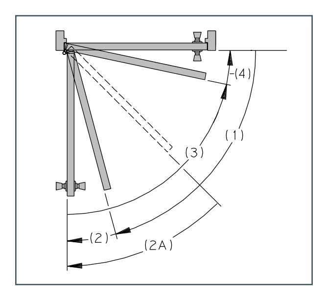
This diagram shows the main part or stages in correct door operation, whether under manual or mechanical control or a combination of the two.
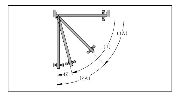
- (1) On the opening swing, the door closers function is to let the door open easily, except at the end of the swing where backcheck is applied.
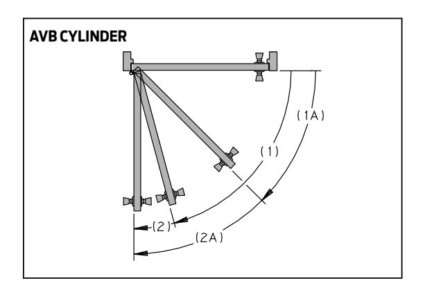
- (2) Backcheck is a feature that cushions the opening swing to prevent the door from slamming into the stop. Special closers designed for potentially abusive applications begin the backcheck function much earlier (2A) such as LCN's advanced variable backcheck (AVB).
- (3) Through the long closing arc, a uniform, reasonable (main) speed should be maintained.
- (4) The latching arc allows the door to close quietly and firmly.
Opening the door builds up the power, which later closes the door.
As a controlled door is opened, the spring of the closer is compressed which builds up the power to close the door. Normally, more opening force would be required as spring compression increases. However, as an LCN closer changes it's arm geometry while the door opens, it increases the door leverage. This offsets the spring compression, resulting in greater ease in opening the door.
In opening, more leverage for the person.
The changing arm geometry gives increased leverage over the door to overcome the growing power of the spring allowing one to pass through the door easily.
In closing, more leverage for the closer.
When the person releases the door and the closer takes over, spring power is applied through the arm system to close the door. Because the spring has been compressed, its power is very high. As the door closes the spring expands, providing the power to close the door.
Special closers for reduced opening force.
The 1990 Americans with Disabilities Act (ADA) and ANSI Standard A117.1 describe maximum opening force limitations for certain non-fire rated doors. The last page of each closer section in the catalog includes a section titled REDUCED OPENING FORCE CLOSERS. This section lists closers in that specific series that will comply with a maximum opening force based on the width of the door.
Any manual door closer, including those certified by BHMA to conform to ANSI Standard A156.4, that is selected, installed, and adjusted based on ADA or other reduced opening force requirements may not provide sufficient power to reliably close and latch the door.
Refer to AUTOMATIC OPERATORS section for information on electric, pneumatic and electromechanical systems that meet reduced opening force requirements without affecting closer power.

HOW TO SELECT A DOOR CLOSER
CONCEALED OR SURFACE MOUNTED CLOSERS?
Door closers are available in two styles - concealed or surface mounted. In choosing a closer style for a particular application, consideration should be given to the type of door being controlled, frame conditions, aesthetic requirements, and control features needed. Information contained in the following material can serve as a guide in selecting the style and model of closer to meet specific requirements.
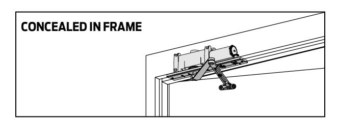
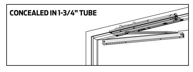
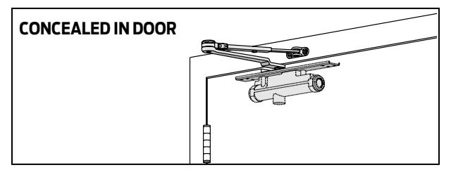
IF CONCEALED, WHERE?
Closers concealed in the head frame over the door are out of sight and entirely out of the pedestrians way. They cannot be harmed by scrub water, cleaning chemicals or floor dirt, and are protected from airborne contaminants, like dust. They are easy to reach for regulation without removing any parts. Closers for frame sections as thin as 1-3/4˝ (44 mm) are available.
Closers located within the door itself are also hidden and protected but recommended for interior doors only.
SURFACE MOUNTED CLOSERS – LOCATION?
Closer location is subject to the considerations of practicality and appearance. Good taste usually decrees that closers on doors along a corridor be located on the room side of the door so they are out of the line of sight from the corridor. Closers should be placed on the inside of exterior doors for appearance and to shelter them from the elements.
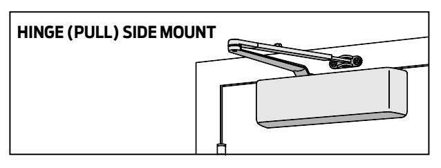
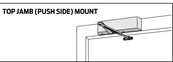
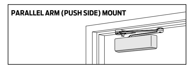
WHERE ARE HEAVY DUTY CLOSERS REQUIRED?
Heavy duty closers should always be used in these places:
- 1) Schools or public buildings where heavy or abusive usage is expected.
- 2) Exterior doors.
- 3) Doors subject to draft, winds, or air pressure differentials.
- 4) High frequency doors such as those on department stores, malls, or mixed use tenancies.

WHICH ARM SYSTEM?
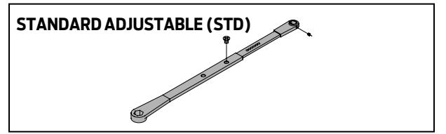
Double lever arm closers can provide control under difficult conditions for either interior or exterior doors. A parallel arm system is a type of double lever arm where the main arm is parallel to the face of the closed door. Available double lever arms:
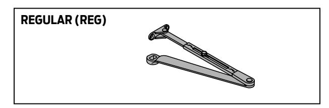
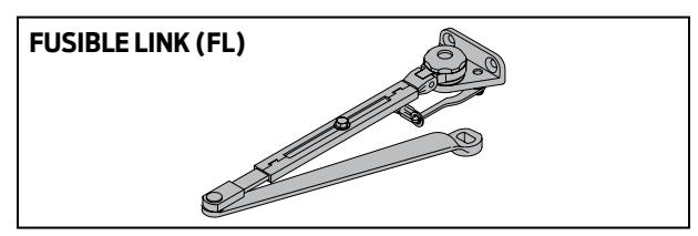
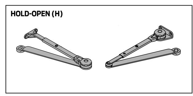
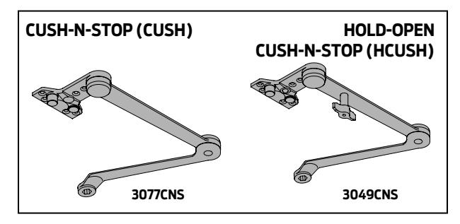
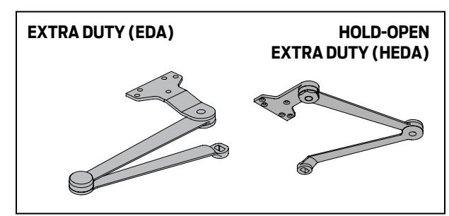
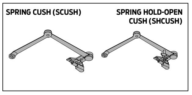
Single lever arm (track) closers may be used on interior or sheltered exterior doors. The hold-open function in a single lever arm system is provided by either the track or the cylinder assembly. Available single lever arms:
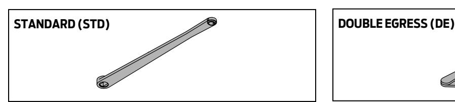
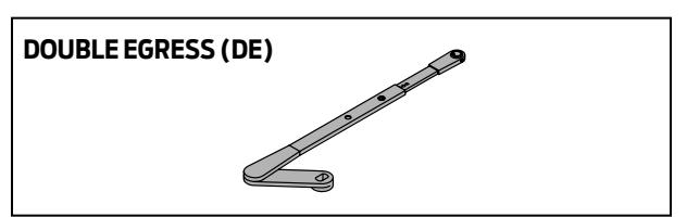
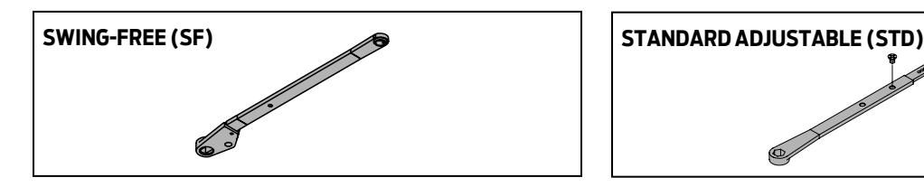
DO YOU NEED SPECIAL CYLINDER FUNCTIONS?
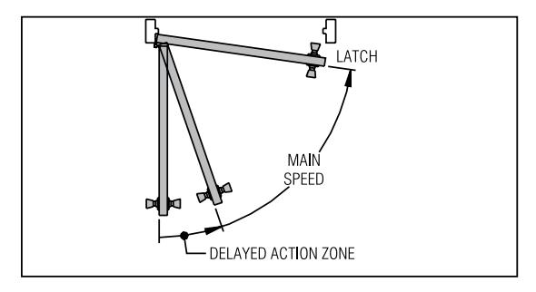
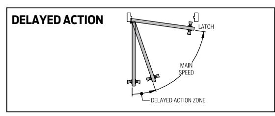
Many LCN closers can be ordered with a delayed action function built into the cylinder. Delayed action (DEL) is a special hydraulic circuit that provides additional time to pass through the door. A special regulating screw controls the closing speed from maximum opening through approximately 75°. After that point the normal main speed resumes control to close the door. Delayed action is not available with single lever arm (track) closers.
Advanced Variable Backcheck (AVB) is available with high security and 4110 series closers to begin cushioning the opening swing at about 45° (2A) instead of the usual 75° (2). AVB is especially suited for potentially abusive applications.
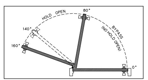
Multi-point (ME series) closer/holders can be ordered with a hold-open bypass at either 80° or 140° function. This feature does not allow hold-open to take effect until opened beyond the selected degree of bypass.
IS SEASONAL ADJUSTMENT REQUIRED?
Temperature changes can affect the operation of common door closers by changing the viscosity of the hydraulic fluid inside the closer. As temperature rises, the fluid thins out and closes the door more rapidly. As temperatures decrease, the fluid thickens causing the closer to close the door very slowly.
LCN uses all weather Ultra X fluid to eliminate the need for seasonal adjustment.
HOW WILL THE DOORS BE HUNG?
While butt hinges provide the most common method of hanging doors, some doors are hung on pivots centered in the door, others on offset pivots. Surface mounted closers will handle doors hung in any of these three
ways. LCN 4020 Series closers can even control a "balanced" door installation. Concealed closers may conflict in location with pivot leaves and thus may require special templating.
HOW FAR SHOULD THE DOOR OPEN?
Three basic rules apply to maximum degree of opening.
- 1. It is best to let the door swing as far as it can swing freely. Some closers are mounted in different locations for different degrees of opening.
- 2. Use a mechanical stop when a door can not swing 180° or at the selected hold-open point of a double lever arm system. The mechanical stop can be mounted on the floor, wall, overhead, or built into the closer arm.
- 3. The closer should be positioned so backcheck takes place well in advance of the stop position to cushion the opening swing and prevent door and frame damage from an abrupt stop.

DOOR DIMENSIONS?
The width of the door is the main consideration in determining the correct closer size. Size here refers to the minimum spring power and hence the closing force, generated by the closer. In the catalog, the interior and exterior TABLE OF SIZES for each closer are set up for ranges of door width and assume normal operating conditions. If a door is of exceptional height, weight, special construction, or if drafts and air pressure differentials exist, increased closer power should be considered.
Door thickness may be a factor. A concealed-in-the-door closer should not be used in a hollow metal door less than 1-1/2˝ (38 mm) thick or a wood door under 1-3/4˝ (44 mm). Exceptionally thick doors can affect hinge and pivot centers to the extent that closer functions and geometry are also affected.
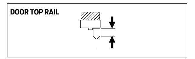
The depth of the doors top rail is important to nearly every closer installation. Narrow top rails may require plates to successfully mount the closer. An insufficient top rail in flush, hollow, or composite filled doors may make concealed-in-the-door installations impractical.
HAND OF A DOOR?
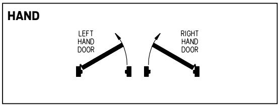
Some door closers are handed. When approaching a door from the push side, if hinged on the left, it is a left hand door; if hinged on the right, it is a right hand door.
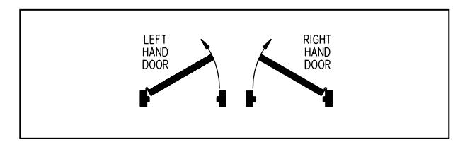
For purposes of handing door closers, right hand reverse bevel and left hand are identical. Also, left hand reverse bevel and right hand are identical.
WILL A STANDARD CLOSER AND TEMPLATE MEET YOUR NEEDS?
Occasionally the physical limitations of the selected closer may not provide the desired functions or degree of opening. Standard templated locations may interfere with other applied hardware. In these situations, contact the LCN Applications Engineering Department for assistance. Customized installation templates or products may be available to solve an unusual application.

WHY USE PLATES, BRACKETS, ADAPTERS AND OTHER SPECIAL PIECES?
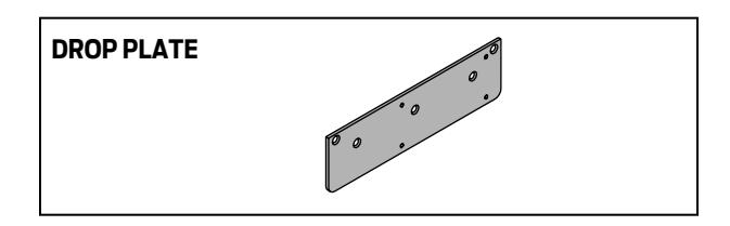
A drop plate is now commonly used to drop (lower) closers to meet special conditions or adapt a closer to door or frame surfaces that are not adequate for normal mounting patterns.
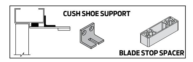
Specialized brackets, adapters, and parallel arm shoes are available to simplify the installation of closers with a variety of frame and door conditions. The most commonly used are listed with each closer. Consult LCN for assistance if you are not sure.
WHAT FASTENERS SHOULD BE USED?
LCN closers are shipped with a wood and machine screw pack or Self-Reaming and Tapping screws (SRT) unless other fasteners are ordered. These screw packs are suitable for wood or properly reinforced hollow metal frames and metal or solid core wood doors. For wood door applications, LCN recommends the use of wood screws. For selected closers, metric machine screws are available in lieu of UNC/UNF machine screws.
When attaching closers to hollow core doors, optional THRU BOLTS (TB) are recommended to minimize crushing or squeezing the door. Thru bolting can also provide a very strong mechanical connection for potentially abusive applications. Because the TB barrel extends completely through the door, the door thickness must be specified when ordering if it is other than 1-3/4˝ (44 mm). TB's are only available for 1/4-20 machine screws.
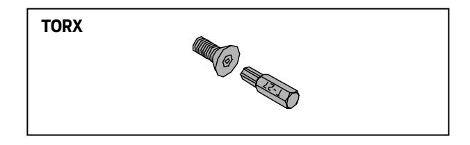
For high security applications, TORX machine screws are available with most closers. These are standard for all exposed fasteners with high security closers. TORX fasteners feature a hex lobular drive with a security pin in the center. They can only be installed or removed with a special set of bits that are available from LCN.
WHAT FINISH IS DESIRED?
LCN powder coating provides superior protection against the effects of weather conditions and is an environmentally friendly process. The high quality, chip resistant finish is far superior to any previously offered. Corrosion resistance surpasses 100 hours salt spray testing (four times the industry standard). Non-metallic components also provide the same high resistance to the effects of the elements. All LCN products must be shipped with a finish.
LCN offers custom finishing services to complement special installations. This provides a custom appearance and all the corrosion resistance inherent in the standard powder coated finishes. It is recommended that the customer submit a physical sample of desired custom finish with the closer order. Custom powder coat finishes are available at additional cost. A metal cover must be ordered when custom powder coat finishes are desired.
With some exceptions, visible components such as covers, arms, fasteners, and finish plates are available in plated finishes. Tracks are painted to complement the plated finish. Hidden assemblies such as cylinders and mounting plates are supplied with a powder coated finish. Plated finishes are available at additional cost.
For installations where a higher level of protection against weathering is required, LCN offers a special rust inhibiting (SRI) process at an additional cost. Metal components receive an SRI pretreatment and a standard or custom powder coat finish. The SRI process with a powder coat finish exceeds the protection level available with powder coated parts. SRI can not be ordered with plated or anodized finishes. All closers must be shipped with a finish.
INSTALLATION PROCESS?
Before installation of the door closer;
- n Review the installation instructions provided with the door closer.
- n Verify the desired installation and template with the hardware schedule. Review other applied door hardware for possible interference.
- n Verify that the frame attachments and door hinges or pivots are securely installed.
- n Verify that the door is hung properly and operates smoothly through it's entire range of opening. Misalignment, sagging or other conditions that prevent free movement of the door must be corrected prior to installation of the door closer. LCN recommends < 1/4 lbf to open the door before
- n Check latching mechanisms for proper operation and release.
installing closers for ADA applications.
- n Verify that the door and frame have specified reinforcements.
- n Verify that all required tools are available.
Complete the installation by;
- n Follow the installation instructions and use fasteners provided with the closer.
- n Using the template provided with the closer, layout, drill and tap (for metal screws) the required mounting holes. Be sure to use the proper size drill bit and tap to ensure maximum holding power by the screws.
- n For closers with adjustable spring power, adjust the cylinder spring power based on the width of the door as described in the installation instructions.
- n The hydraulic back check, main speed and latch speed regulation adjustments of the door closer have been adjusted at the factory to meet normal installation conditions. If further adjustments are required to the hydraulic regulation, follow the directions included with the installation instructions.
- n Lightly wipe the cover and arm surfaces with a soft, clean, dry cloth to remove any dirt or smudges that occurred during the installation.

Arm Options
STD - Standard Arm REG - Regular Arm
Rw/PA - Regular Arm with Parallel Arm Shoe R/62A - Regular Arm with Auxiliary Parallel
Arm Shoe H - Hold Open Arm
Hw/PA - Hold Open Arm with Parallel Arm Shoe
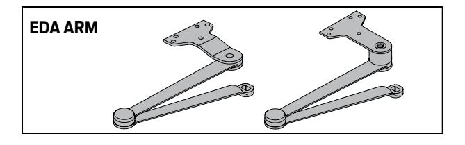
LONG - Long Arm XLONG - Extra Long Arm HLONG - Hold Open Long Arm EDA - Extra Duty Arm
EDAw/62G - Extra Duty Arm with Thick Hub Shoe
HEDA - Hold Open Extra Duty Arm HEDAw/62G - Hold Open Extra Duty Arm
w/ Thick Hub Shoe
CUSH - Cush -n- Stop Arm
HCUSH - Hold Open Cush -n- Stop Arm SCUSH(SCNS) - Spring Cush -n- Stop Arm
SHCUSH(SHCNS) - Spring Hold Open
Cush -n- Stop Arm SF - Swing Free Arm DE - Double Egress Arm
FL - Fusible Link Arm
Control Box Options
SC - Standard Control Box
Cylinder Options
STD - Standard Cylinder DEL(DA) - Delayed Action Cylinder AVB - Advanced Variable Backcheck B80 - Bypass 80 Degree ME Cylinder B140 - Bypass 140 Degree ME Cylinder
TEL - Telephone Cylinder
Cover Option
STD - Standard Plastic Cover
MC - Metal Cover FC - Full Cover CL - Cover Length DS1 - Designer Series Cover
Track Options
STD - Standard Track HO - Hold Open Track BUMPER - Track with Bumper
HBUMPER - Hold Open Track with Bumper
Fastener Pack Options
WMS - Wood & Machine Screws
TBWMS - Thru-Bolt, Wood & Machine Screws SRT - Self Reaming & Tapping Screws
TBSRT - Thru-Bolt, Self Reaming & Tapping Screws
TORX - 'TORX' Machine Screws
TBTRX - Thru-Bolt, 'TORX' Machine Screws
UNIV - Universal Screw Pack
Motor Gearbox Options
SF - Standard Force Motor Gearbox
Powder Coat Finishes
AL - Aluminum DKBRZ - Dark Bronze STAT - Statuary Bronze LTBRZ - Light Bronze BLK - Black BRASS - Brass
Miscellaneous Terms
ELR - Extra Long Rod SRI - Special Rust Inhibitor SE - Single Point Electronic ME - Multi-Point Electronic PAH - Parallel Arm Holder
HSA - Hold Open / Scanner Activated ES - Electric Strike Relay (Control Boxes)
S - Sequential (Control Boxes)
RF - Radio Frequency TJ - Top Jamb PA - Parallel Arm G - Flush Ceiling T - Track
DPS - Door Position Switch
LR - Long Rod ST - Special Template RH - Right Hand LH - Left Hand HL - Header Length DD - Double Door Header POS - Positive Mechanical Stop BKY - Panic Breakaway Stop
XP - Extra Protection
A22 LCN Door Control Catalog
A ADA – Americans with Disabilities Act.
ADVANCED VARIABLE BACKCHECK CYLINDER (AVB) – Optional cylinder that starts backcheck at about 45° (2A) instead of the normal 75°(2).
ANODIZED – An electrochemical process that thickens and toughens the protective oxide on aluminum metal.
ANSI – American National Standards Institute publishes standards for commercial hardware. A156.4 is the basic door closer standard.
APPLIED STOP – Surface mounted stop attached to a cased opening frame.
ARCH TOP DOOR – Any door with an arched top rail.
ARMATURE EXTENSION – Standard metal extensions available for SEM magnets where the armature does not reach the magnet. Available in 1/2", 3/4", 1", 2", 4" or a kit including all sizes.
AUTOEQUALIZER™ – An LCN specific term for an electric or a pneumatic power operator. System is low-energy & carries a two-year warranty.
AUTOMATIC OPERATOR – A term used to describe a type of automated opening system.
AUXILIARY DOOR STOP – Hardware designed and installed to limit the swing of a door.
B
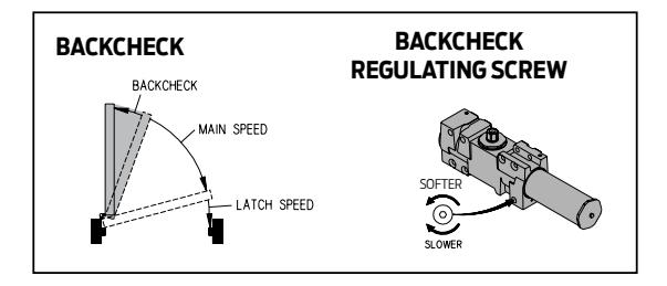
BACKCHECK – Hydraulic circuit designed to cushion the doors opening swing at about 75°. Standard on all LCN closers.
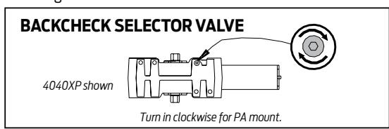
BACKCHECK SELECTOR VALVE – Valve used to provide proper backcheck location for 4040XP and 4050 parallel arm mounting.
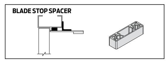
BLADE STOP – Narrow frame stop that will not accept a parallel arm shoe.
BLADE STOP SPACER – Spacer lowers a parallel arm 1/2″ so the arm will clear a blade stop.
BLOW-OPEN – A type of control box that is used for a smoke evacuation system. Can be used with or without a normal power operator system.
BRIGHT METALLIC – Custom powder coat finish, which resembles that of US26 or US26D plated finish.
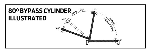
BYPASS CYLINDER – ME cylinder that will not hold-open within a specified range of door swing.
C
CASED OPENING – Frame section without stops.
CAST ALUMINUM – Material used in producing LCN's competitively priced door closers.
CAST IRON – Material used in producing high quality door closers.
CLEARANCE – Distance from a PA SHOE to the push side of door or distance from the pull side of door to the wall on installations.
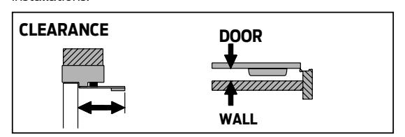
CLOSING FORCE – Energy generated by a closer to close and latch the door.
CONTROL BOX, Standard, 9100 SERIES – Microprocessor door control without Power Boost or built in power supply.
CONTROL BOX, 2800, 9500 SERIES – Microprocessor door control, includes adjustment for opening, closing & backcheck speeds. Features Push 'N Go & Power Boost.
CONTROL BOX, 7900 SERIES – Heavy duty, surface mounted control box that contains one or two electrically controlled pneumatic circuits.
CONTROLLER ASSEMBLY – Digital control suite used in the LCN electric power operator. Includes adjustments for opening force and opening speed.
CONCEALED IN DOOR – Closer with cylinder concealed in the top rail of the door with either an exposed or concealed arm.
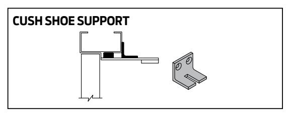
CUSH SHOE SUPPORT – Support provides fifth screw anchorage of CUSH shoes on frames with narrow push side reveals.
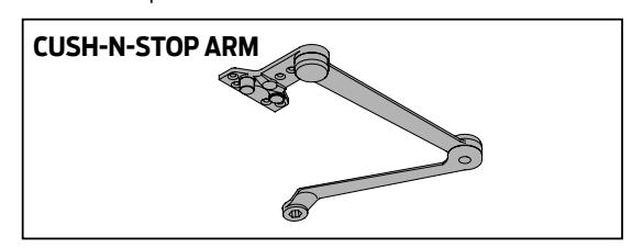
CUSH-N-STOP ARMS (CUSH) – Extra duty, parallel arm that includes a stop in the CUSH shoe.
CUSTOM POWDER COAT (RAL) – An optional powder coat finish. Currently, LCN offers a wide selection for special powder coat finishes. LCN uses a European color standard, referred to as an RAL #, to differentiate between finishes.
CUTOUT – Preparation of the top rail of a door or frame for concealment of the closer, arm or track.

CYLINDER ASSEMBLY – Main closer component complete with any mounting plates or electronics.
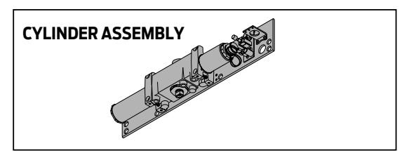
CYLINDER ONLY – Hydraulic cast iron cylinder.
D
DEEP REVEAL – Reveal deeper than what an arm will accommodate.
DELAYED ACTION (DEL) – Delays closing from maximum opening to approximately 75°.
DESIGNER SERIES COVER (DS1) – An aesthetically pleasing cover design that appeals to many types of facilities & architects.
DOOR POSITION SWITCH (DPS) – A security option specific to the 2210 Series closer. A door position switch is used to monitor the closed position of a door in an opening.
DOUBLE DOOR HEADER – One automatic electromechanical power operator and one manual door within the same header, for a pair of doors.
DOUBLE ACTING – Term used to describe door swing. A double acting frame does not have a stop thus allowing the door to swing 95° in both directions.
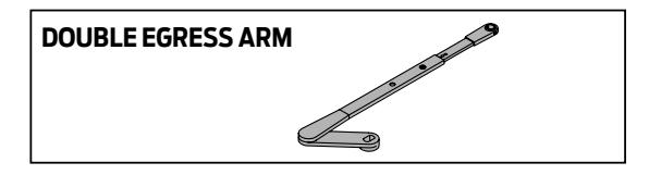
DOUBLE EGRESS ARM (DE) – Designed for pull side installation on double egress frames. Actual arm varies depending on selected closer.
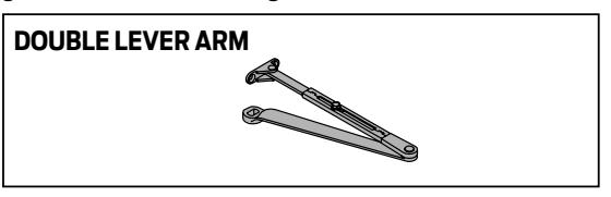
DOUBLE LEVER ARM – Two-part arm hinged at the elbow that provides superior leverage. Used on hinge side, top jamb and parallel arm mountings, the geometry of the arm provides greater mechanical advantage to the closer.
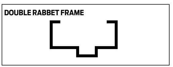
DOUBLE RABBET FRAME – Frame with a recess or offset formed on both sides of a stop to receive a door.
DROP PLATE – Designed to mount a closer on top rail or head frame to meet special conditions or mounting surface dimensions that are below minimums
E
ELECTRIC STRIKE – An optional, electronic latching device that replaces a regular lock strike in a doorframe that allows the door to open from a remote location or by special access equipment.
ELECTRIC STRIKE RELAY (ES) – An optional feature found in an LCN 7900 Series control box that can be used to control an electric strike.
ELECTROHYDRAULIC POWER OPERATOR – Power operator with an electrically controlled opening feature and hydraulic closing feature.
ELECTROMECHANICAL POWER OPERATOR – Power operator with an electrically controlled opening feature and closing feature.
ESCUTCHEON – An optional, protective or decorative plate that can be installed with many surface mounted actuators.
E - H
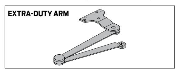
Glossary of terms EXTRA DUTY ARM (EDA) – Double lever arm with both main and forearm made of solid forged steel for extra strength.
EXTRA LONG ARM (XLONG) – 4040XP Series double lever arm for exceptionally deep reveals or other special applications.
F
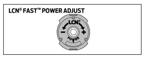
(LCN®) FAST™ POWER ADJUST – A green dial located on the end of the spring tube on selected heavy duty closers. Designed to help installers accurately adjust the closer power to match the conditions of the entrance.
FIFTH SCREW – Mounting screw farthest from the door on a parallel arm shoe.
FIFTH SCREW SPACER – Supports PA shoe mounted on frame stop.
FINISH PLATE – Decorative plate applied to overhead concealed closer to conceal closer mounting plate and screws.
FIRE SHIELD – 22-gage steel liner mounts in the track mortise of the door's top rail for 20 minute labeled wood doors.
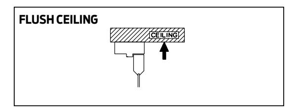
FLUSH CEILING – Condition when the ceiling is at the same height as the top of the frame.
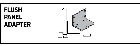
FLUSH PANEL ADAPTER – Adapter provides PA shoe mounting surface when door and frame are flush.
FOREARM – Arm part that connects main arm to the shoe attachments in a double lever arm system.
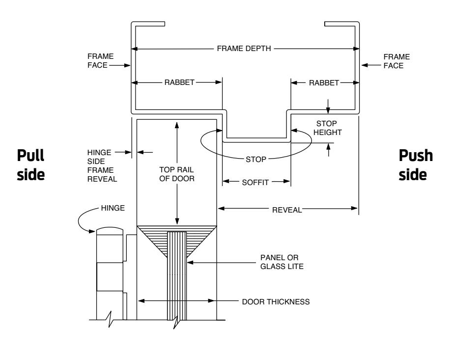
FRAME DEPTH – Face to face dimension of the frame.
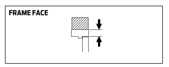
FRAME FACE – Exposed part of frame parallel to face of the wall.
FULL COMPLIMENT BEARINGS – Low friction, high load needle bearings found in all LCN closers.
FULL COVER (FC) – Cover that encloses cylinder assembly except for shaft/arm attachment.
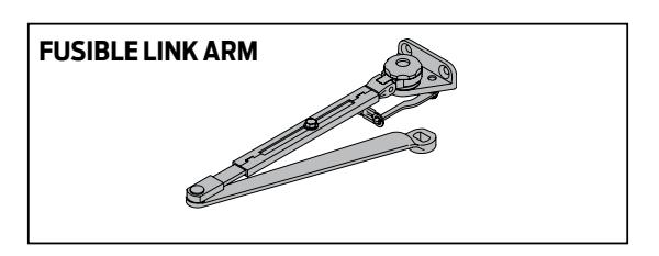
FUSIBLE LINK ARM (FL) – Releases hold-open function when exposed to high temperatures. 135°F and 165°F available.
H
HAND – Direction of a doors' swing, either right or left.
HANDED – Closer or part designed for ONLY right or left swinging doors.
HEAD FRAME – Member of the frame above the door.
HEADER – Aluminum enclosure for motor gearbox & controller.
HINGE SIDE – Face of door and frame on which the hinge pivot point is located.
HINGE SIDE MOUNT – Mounting with the closer cylinder on the hinge side of the door top rail.
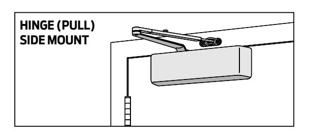
HINGE SIDE REVEAL – Depth measured from the frame face to the pull side of the door face.
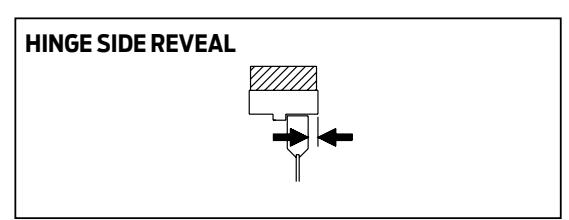
HINGE STILE – Vertical member of a door prepared for installation of hinges.
HOLD-OPEN ARM (H) – Double lever arm that provides holdopen function that is either adjustable at elbow or shoe.
HOLD-OPEN CLIP – Located in track to provide hold-open function for single lever arms.
HOLD-OPEN CUSH (HCUSH) – Parallel arm that features solid forged steel main arm and forearm with stop in soffit shoe. Uses control handle to select hold-open function.
HOLD-OPEN LONG ARM (HLONG) – Hold-open arm extended by a long head and tube for deep reveals.
HOLD-OPEN TRACK with BUMPER (HBUMPER ) – Track with hold-open clip and bumper assembly installed.
HOLDER SCANNER-ACTIVATED (HSA) – Electrically controlled closer/holder with built-in scanner.
HYDRAULIC FLUID – Fluid metered by valve system to control door.
I
INDEPENDENT PAIR – Two automatic doors that function separately.
J
JAMB – The vertical member that forms the sides of a door frame. There is a hinge side jamb and a strike side jamb.
L
LABELED DOOR – Conforms to all applicable codes, requirements, and procedures governing fire rated doors and bears the manufacturer's identification label.
LATCH SPEED – Separate adjustment to control the last few degrees of the door's closing swing.
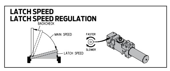
LOCK STILE – Vertical member of a door prepared for installation of a lock.
LONG ARM (LONG) – Extended arm for deep reveals or other special applications.
LOW ENERGY OPERATOR – A type of automated opener used on a door that should take approximately 5 seconds to open to 90°. Low Energy operators do not require safety devices or guide rails. Conforms to ANSI A156.19.
M
MAIN ARM – Connects to the cylinder in a double lever arm system.
MAIN SPEED – Separate adjustment to control closing swing of the door to within a few degrees of latch.
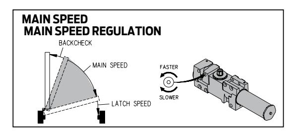
MAXIMUM OPENING – Furthest degree of door opening.
METAL COVER (MC) – Stamped metal cover required for optional plated finishes and custom powder coat finishes. Standard cover with High Security Series closers.
MOTOR CLUTCH – The geared assembly in an LCN electric power operator. Once activated, the motor clutch drives the door open.
MOTOR GEARBOX – Electromechanical drive unit.
General informatior
Glossary of terms
M-P
MORTISE – Material removed from frame and/or top rail of door.
MOUNTING/FINISH PLATE – Plate with exposed mounting screws and finish applied.
MULTI-POINT HOLD-OPEN (ME) – Infinite hold-open points from 0° up to maximum opening.
N
NO DESTRUCT FEATURE – A feature specific to the motor clutch assembly portion of an LCN electric power operator. This feature does not allow the user to back drive the motor, which could cause damage to the unit.
NON-HANDE D – Closer or part designed for both right and left hand swinging doors.
NON-SIZED – Cylinder assembly with spring power adjustable over a range of sizes.
0
OPENING FORCE – Force required to open the door against the closers spring power.
OVERHEAD CONCEALED – Closer with cylinder concealed in head frame and either a concealed or exposed arm.
P
PA SHOE ADAPTER – Adapter provides horizontal mounting for PA shoe on a flush door and frame.
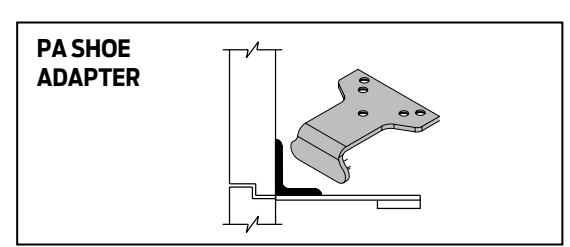
PA SHOE – Attaches the forearm to the soffit for a parallel arm system.
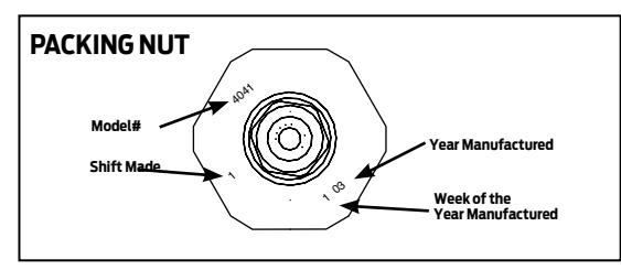
PACKING NUT – A threaded part that holds the pinion in place. Usually, the LCN model number and date of manufacture are stamped into this part. The date of manufacture is important because the owner can determine if the cylinder is in or out of warranty.
PANIC BREAKAWAY STOP – An optional safety device that permits egress on in-swinging exterior doors by allowing them to swing out in case of an emergency. Used with overhead concealed, center pivoted in-swinging doors.
PARALLEL ARM – A push side mounted double lever arm system where main arm is parallel to the door when in the closed position.
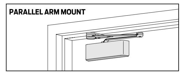
PARALLEL ARM HOLDER (PAH) – An item usually used on the inactive leaf of a pair of doors for hold-open where the active leaf has a closer installed.
PINION – Transfers rotary motion of the arm system to the piston. Also provides attachment of arms to closer.
PISTON – One of the internal pieces of a door closer. The piston is moved by the rotating pinion, which in turn compresses the spring.
POSITIVE MECHANICAL STOP – Door stop for overhead concealed, center pivoted out swinging doors.
PNEUMATIC – This type of LCN Automatic Operator is driven by an air source. The air source can be built into the control box or provided separately within the building.
POWER BOOST – Provides additional closing force to ensure latching.
POWER OPERATOR – A term used to describe a type of automated opening system. Refer to "Automatic Operators".
POWDER COAT – A standard finishing process that provides a very durable, corrosion resistant covering to the majority of products that LCN offers. An LCN powder coat finish offers over four times the ANSI salt spray test of 25 hours.
PULL SIDE – Hinge side of door.
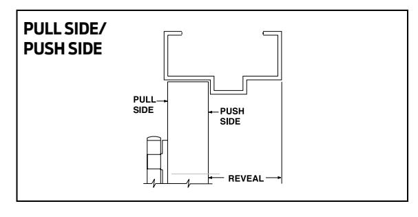
PUSH SIDE – Face of door on stop side of frame.
PUSH 'N GO – Provides power opening after partial (5°) manual opening of door.
Q QUICK FIX PLATE™ – Retrofit mounting plate for the LCN 1260 closer used for closer replacement in push/pull applications.
R
RABBET – Recess or offset formed in the face to receive a door.
RADIO FREQUENCY (RF) – A method of actuating LCN Automatic Operators. A RF transmitter signals a RF receiver to open a door.
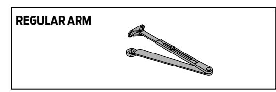
REGULAR ARM – A double lever, non hold-open arm.
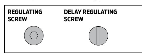
REGULATING SCREW – Valve that adjusts flow of hydraulic fluid within cylinder to control door closing speed.
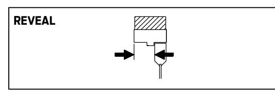
REVEAL – Depth measured from the frame face to the door face.
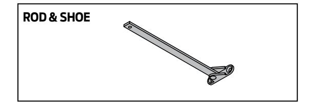
ROD & SHOE – Part of forearm that provides adjustable length feature for double lever arms.
S
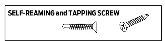
SELF-REAMING and TAPPING SCREW (SRT) – Philips head screw with self-reaming and self-tapping capability used in mounting installations.
SECOND CHANCE FEATURE – A feature that allows the Automatic Operator two attempts at opening the door. If resistance is encountered on the first attempt, the operator will pause and then try a second time. This feature is standard on the LCN electric automatic operators.
SEM – SEM is short for 'single-point electronic magnet'. An actual product number is required when ordering.
SENTRONIC – A general term for the fire/life safety products that are offered by LCN.
SEQUENCE – An option to the LCN series of automatic operators. This option allows a pair of vestibule doors to open one after the other.
SHOE – Attaches forearm to frame or door face in a double lever arm system.
SIMULTANEOUS PAIR – Two automatic doors that open at the same time.
SINGLE POINT HOLD-OPEN (SE) – Electrically controlled hold-open using a special track and single lever arm.
SINGLE LEVER (STANDARD) ARM (STD) – Directly connects cylinder and track/roller assembly on the door or frame
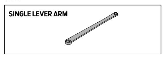
SINGLE RABBET FRAME – Frame with a recess or offset formed on one side of a stop to receive a door.
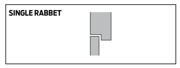
SIZED – A closer with a specific closer power for proper door applications.
SLIDER – This part is used in conjunction with a track roller in a Sentronic track assembly.
Glossary of terms SLIM LINE COVER – A over that conceals the cylinder but exposes both pinion shafts.
SOFFIT – Horizontal surface of a frame between vertical stops on a double rabbet frame.
SOFFIT SHOE – Connects parallel arm shoe to soffit.
SPECIAL RUST INHIBITOR (SRI) – A special corrosion resistant pre-treatment that is available for most LCN closers. Adding SRI to the standard LCN powder coat finish gives the closer a tremendous advantage over a potentially corrosive environment.
SPECIAL TEMPLATE (ST) – A special template is usually a modification to a standard product. Either the product itself changes location in the opening or a component is modified from the standard offering to accommodate other hardware or door and frame dimensions.
SPRING CUSH ARM (SCUSH) – Non-handed parallel arm for abusive applications. Features solid forged steel main arm and forearm with spring loaded stop in the soffit shoe.
SPRING HOLD-OPEN CUSH ARM (SHCUSH) – Non-handed parallel arm for abusive applications features solid forged steel main arm and forearm with spring loaded stop in the soffit shoe. Uses control handle to select hold-open function.
SPRING POWER – Closing force exerted by the spring inside the cylinder to close the door.
SPRING POWER ADJUSTMENT – Mechanical pre-loading of spring to adjust closing force.
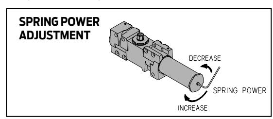
SPRING TUBE – Part of the closer assembly that contains the spring.
STANDARD CYLINDER – Cylinder with main speed, latch speed, and backcheck adjustments.
STANDARD TRACK – Non hold-open track.
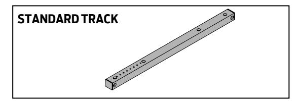
STOP – Part of frame against which the door closes.
STOP HEIGHT – Distance the stop extends below the frame face.
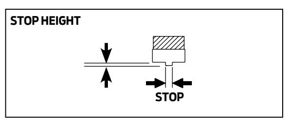
SWING FREE ARM – ME arm designed to allow free movement of the door without disengaging the holding mechanism.
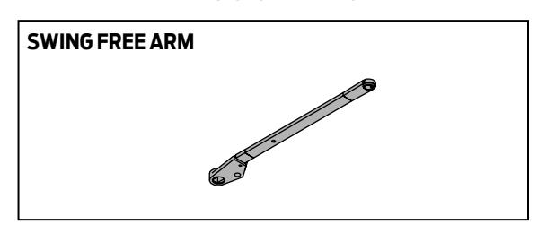
T
TBSRT – Thru bolts and self-reaming and tapping screw package.
TBTRX – Thru bolts and TORX security machine screw package.
TBWMS – Thru bolt, wood and machine screw package.
THICK HUB SHOE – Substituted for soffit shoe on EDA arm to clear blade stop.
TOP JAMB – Mounting with closer installed on frame face.
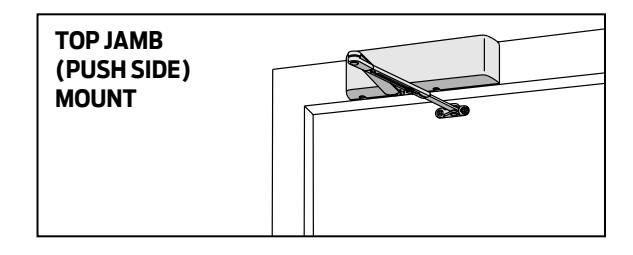
TOP RAIL – Horizontal top member of a door that connects the latch and hinge stiles. Height is measured from stop on push side.
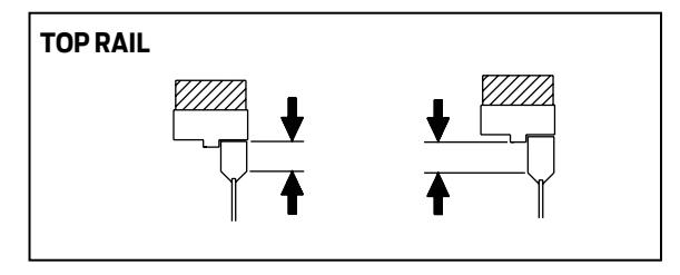
T-W
TORX – Security machine screw with TORX drive and security pin for tamper resistant applications.
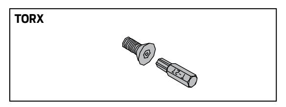
TRACK BUMPER – Mounts in track to cushion opening swing, but reduces maximum opening. This is not a substitute for a mechanical door stop.
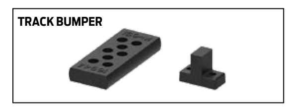
TRANSFORMER – Electrical device to reduce voltage from 120V AC to 24V AC.
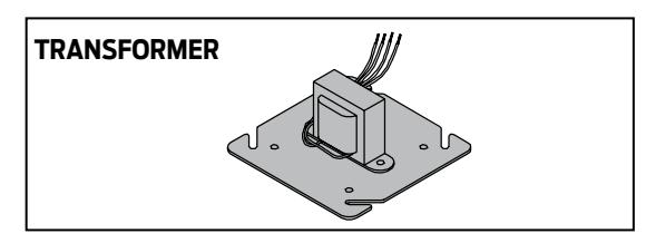
TRI-VOLTAGE – SEM magnets available with current inputs of 12v, 24v and 120v.
U
ULTRA LIQUID X – All weather fluid that does not change viscosity over a wide temperature range.
UNIVERSAL – A term used to describe a door closer. Closers of this nature are non-sized and non-handed.
V
VESTIBULE – A small lobby or entrance that has at least two doors. One door is to the exterior and the other to the interior of the building. A variation could be multiple doors or banks of doors.
W
WMS – Standard wood and machine screw package.
WOOD MOUNTING CLIP – Designed to ease installation of concealed closer in wood frame.

|
|
||
|
|
|
|
|
|
|
|
|
|
|
|
|
|
|
|
|
|
||
|
|
||
|
|
||
|
|
||
|
|
||
|
|
||